Page is loading ...

1
Owner’s Manual
1111 W. 35th Street, Chicago, IL 60609 USA • www.tripplite.com/support
Copyright © 2012 Tripp Lite. All rights reserved. SmartOnline is a trademark of Tripp Lite.
SmartOnline™
Single-Phase 5kVA–6kVA
Intelligent True On-Line UPS Systems (Rackmount/Tower)
• Includes UPS system with internal battery system (5&6kVA), detachable PDU and detachable
parallel PDU modules (6kVA) • Rackmount and tower adaptable
Not suitable for mobile applications.
Important Safety Warnings 2
Mounting 3
Connection 9
Features 4
Internal Battery Replacement 28
Español 30
Storage and Service 29
Français 59
Warranty and Warranty Registration 29
Ðóññêèé 88
Optional Connection 12
Manual Bypass Operation 14
Operation 15
Warranty
Registration:
register online today for a
chance to win a FREE Tripp Lite
product—www.tripplite.com/warranty
201207113 933070.indb 1 9/17/2012 1:19:41 PM

2
Important Safety Warnings
SAVE THESE INSTRUCTIONS. This manual contains important instructions and warnings that should be followed during the
installation and maintenance of this product. Failure to heed these warnings may affect your warranty.
UPS Location Warnings
• Install your UPS in a structurally sound area. Your UPS is extremely heavy; take care when moving and lifting the unit.
• Only operate your UPS at indoor temperatures between 32° F and 104° F (between 0° C and 40° C). For best results,
keep indoor temperatures between 62° F and 84° F (between 17° C and 29° C).
• Leave adequate space around all sides of the UPS for proper ventilation.
• Do not install the UPS near magnetic storage media, as this may result in data corruption.
• Do not mount unit with its front or rear panel facing down (at any angle). Mounting in this manner will seriously
inhibit the unit’s internal cooling, eventually causing product damage not covered under warranty.
UPS Connection Warnings
• Isolate the UPS before working on this
circuit.
• The power supply for this unit must be
single-phase rated in accordance with
the equipment nameplate. It also must
be suitably grounded.
Equipment Connection Warnings
• Use of this equipment in life support applications where failure of this equipment
can reasonably be expected to cause the failure of the life support equipment or
to significantly affect its safety or effectiveness is not recommended. Do not use
this equipment in the presence of a flammable anesthetic mixture with air, oxygen
or nitrous oxide.
• Connect your UPS power module’s grounding terminal to a grounding electrode conductor.
• The UPS is connected to a DC energy source (battery). The output terminals may be live even when the UPS is not connected
to an AC supply.
Maintenance Warnings
• Your UPS power module and battery module(s) do not require routine maintenance. Do not open them for any reason. There
are no user-serviceable parts inside.
Battery Warnings
• Connect only Tripp Lite battery modules (of the correct type and voltage) to your UPS power module’s external battery
connector.
• Batteries can present a risk of electrical shock and burn from high short-circuit current. Observe proper precautions. Do not
dispose of the batteries in a fire. Do not open the UPS or batteries. Do not short or bridge the battery terminals with any
object. Unplug and turn off the UPS before performing battery replacement. Use tools with insulated handles. There are no
user-serviceable parts inside the UPS. Battery replacement should be performed only by authorized service personnel using the
same number and type of batteries (Sealed Lead-Acid). The batteries are recyclable. Refer to your local codes for disposal
requirements or visit www.tripplite.com/UPSbatteryrecycling for recycling information. Tripp Lite offers a complete line of UPS
System Replacement Battery Cartridges (R.B.C.).Visit Tripp Lite on the Web at www.tripplite.com/support/battery/index.cfm to
locate the specific replacement battery for your UPS.
• Fuses should be replaced only by factory authorized personnel. Blown fuses should be replaced only with fuses of the same
number and type.
• Service and repair should be done only by trained personnel. Prior to any service work performed on hardwired power modules,
they should be turned off or manually bypassed via the transformer. Prior to any service work performed on power modules that
plug directly into wall outlets, they should be turned off and unplugged. Note that potentially lethal voltages exist within this unit
as long as the battery supply is connected.
• Do not connect or disconnect battery module(s) while the UPS is operating from the battery supply or when the transformer
module is not in bypass mode (if your UPS system includes a transformer module with a bypass switch).
• During “hot-swap” battery module replacement your UPS will be unable to provide battery backup in the event of a blackout.
• Only connect compatible battery module(s).
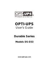
Legend
B—Contactor solenoid.
Q—Mains input thermal-magnetic switch.
T—Two-pole contactor 100 A AC1; coil voltage: according to the mains input.
Remark: Q needs to use the approved component of Safety Certification.
External power
distribution unit
UPS
L
Q
B
T
N
L
N
UPS Power Rating Upstream Circuit Breaker
5kVA N/A
6kVAC curve - 40A
GL1
L1
2 poles circuit breaker
To UPS Normal AC source
L2(N)
L2(N)
Required Protective Devices and Cable Cross-Sections
Recommended upstream protection
201207113 933070.indb 2 9/17/2012 1:19:42 PM

3
Mounting
4-Post Mounting
1
The included plastic pegs
A
will temporarily support the empty rackmount shelves
B
while you install the permanent mounting hardware. Insert a peg near the center of
the front and rear bracket of each shelf as shown. (Each front bracket has 6 holes
and each rear bracket has 3 holes.) The pegs will snap into place.
After installing the pegs, expand each shelf to match the depth of your rack rails. The
pegs will fit through the square holes in the rack rails to support the shelves. Refer to
the rack unit labels to confirm that the shelves are level in all directions. Note: The
support ledge of each shelf must face inward.
2
Secure the shelves
B
to the mounting rails permanently using the included screws
and cup washers
C
as shown.
• For 4U equipment mounting, place 6 screws total at the front and 4 screws total
at the back.
Tighten all screws before proceeding.
Warning: Do not attempt to install your equipment until you have inserted and
tightened the required screws. The plastic pegs will not support the weight of
your equipment.
3
Attach mounting ears
D
to the front mounting holes of your equipment
E
using
the screws provided
F
. The ears should face forward.
Note: It is recommended that you remove the internal batteries of the UPS prior to
installation. This will remove excess weight and will allow safer handling of equipment.
See Internal Battery Replacement section for battery removal instructions.
Mount your equipment in either a 4-post or 2-post rack or rack enclosure. The user must determine the fitness of hardware and
procedures before mounting. If hardware and procedures are not suitable for your application, contact the manufacturer of your
rack or rack enclosure. The procedures described in this manual are for common rack and rack enclosure types and may not be
appropriate for all applications.
12kVA UPS Configuration—SU12KRT4UHW Only (Using 2 6kVA Power Modules)
2-Post Mounting (Optional)
To mount your 5kVA or 6kVA UPS in a 2-post rack, you must purchase a Tripp Lite 2-Post Rackmount Installation Kit (model:
2POSTRMKITHD, sold separately) for each power module and battery pack installed. See the Installation Kit’s owner’s manual for
complete mounting instructions.
Note: 2-post mounting is not recommended for 12kVA UPS systems.
4
Using an assistant, lift your equipment and slide it onto the mounting shelves.
Attach your equipment to the rack by passing the screws, nuts and washers (user-
provided)
G
through its mounting ears and into the rack rails. Be sure to use separate
rack rails for each individual component.
See manual included with parallel PDU for SU12KRT4UHW Mounting.
3
E
D
G
F
4
1
B
B
A
A
A
2
B
B
C
C
14
SW
14
SW
201207113 933070.indb 3 9/17/2012 1:19:45 PM

4
Mounting
To mount the UPS in an upright (tower) position, Tripp Lite’s 2-9USTAND accessory
is required (sold separately).
Once mounted, rotate the power module’s Control Panel for easier viewing while the
UPS is upright. Insert a small screwdriver, or other tool, in the slots on either side of
the Control Panel. Pop the panel out, rotate it, and pop the panel back into place.
Features
Before installing and operating your UPS, familiarize yourself with the location and function of the features of each component.
Power Module Front Panel Controls
1
LCD DISPLAY: This backlit (16 × 2 character) dot matrix display indicates a wide
range of UPS operating conditions and diagnostic data. It also displays UPS
settings and options when the UPS is in setup mode.
2
ON/MUTE BUTTON: Press this button and hold it until you hear a beep to turn
the UPS system’s inverter ON. If the UPS’s battery alarm is sounding, press this
button to silence it.
3
SCROLL DOWN/EXIT SETUP BUTTON: This button allows you to browse through
different options and power readings on the LCD display. Momentarily pressing it
causes the LCD screen to display a different power reading (see “Operation”
section). Pressing it and the SCROLL UP button together puts the UPS in setup
mode, where this button is used to scroll through setup options and to exit setup
mode.
4
SCROLL UP/SELECT BUTTON: This button allows you to browse through different
options and power readings on the LCD display. Momentarily pressing it causes
the LCD screen to display a different power reading (see “Operation” Section).
Pressing it and the SCROLL DOWN button together puts the UPS in setup
mode, where this button is used to select setup options.
5
OFF BUTTON: Press this button until you hear a beep to turn the UPS system’s inverter OFF.
6
O/P (OUTPUT) LED: This green light will illuminate to indicate your UPS is supplying AC power to connected equipment.
7
DC/AC (INVERTER) LED: This green light will illuminate to indicate the UPS’s DC/AC inverter is activated.
8
BYPASS LED: This yellow light will flash when the UPS is providing filtered mains power without engaging the converter or
inverter. If this LED is flashing, connected equipment will not receive battery power in the event of a blackout. If Economy Mode
is enabled, this LED will be on solid and the connected equipment will receive power in the event of a blackout.
9
AC/DC (Converter) LED: This green light will illuminate to indicate the UPS’s AC/DC converter is charging the connected
battery pack(s).
10
BATTERY LED: This green light will illuminate when the UPS is discharging the battery to provide connected equipment with AC
power. An alarm will sound which can be silenced by pressing the ON/MUTE button. This LED will remain lit after the alarm is
silenced.
11
I/P (INPUT) LED: This green light will illuminate to indicate an AC input supply is present.
Tower Mounting
11
2
1
3 4 5
10 79 68
201207113 933070.indb 4 9/17/2012 1:19:46 PM

5
Features (Rear Panel) See “Features” section for feature descriptions
SU5000RT4UHV—5kVA UPS System
SU6000RT4UHV—6kVA UPS System with NEMA PDU
SU6000RT4UHVHW—6kVA UPS System with Hardwire PDU
1
EPO
PARALLEL
RS-232
RS-232
ACC. SLOT
AC INPUT
BATTERY
CABLE UNDER LOAD.
DO NOT DISCONNECT
192VDC
CONNECTOR
BATTERY
CAUTION:
BREAKER 20A
OUTPUT 2
200-240Vac
OUTPUT 1
200-240Vac
30A
USB
14
EPO
PARALLEL
RS-232
RS-232
ACC. SLOT
USB
NORMAL
BY
PASS
EPO
PARALLEL
RS-232
RS-232
ACC. SLOT
USB
NORMAL
BY
PASS
9
9
9
8 7 4
8 6 5 4 37
16 15 4 5
6 3
10
10
10
11
11
11
12
12
12
13
13
13
1
1
1
2
201207113 933070.indb 5 9/17/2012 1:19:48 PM

6
Features (Rear Panel) (continued) See “Features” section for feature descriptions
SU6000RT4UHVG—6kVA UPS System with IEC PDU
SU12KRT4UHW—12kVA UPS System and Parallel PDU Modules
Note: See the manual included with the Parallel PDU for 12kVA installation, configuration and setup instructions.
EPO
PARALLEL
RS-232
RS-232
USB
EPO
PARALLEL
RS-232
RS-232
USB
EPO
PARALLEL
RS-232
RS-232
USB
NORMAL
BY
PASS
9
9
4
4
20
20
19 18 17 16
21 217 7 5 15
10
10
11
11
12
12
13
13
4
1
1
15
2
2
18
17
11
23
22
201207113 933070.indb 6 9/17/2012 1:19:50 PM

7
14
EPO
PARALLEL
RS-232
RS-232
ACC. SLOT
USB
NORMAL
BY
PASS
Features (Rear Panel) (continued) See “Features” sectiion for feature descriptions
SU6000RT4UTF—6kVA UPS with NEMA PDU and 6KVA Isolation Transformer
EPO
PARALLEL
RS-232
RS-232
ACC. SLOT
USB
NORMAL
BY
PASS
16 15
SU6000RT4UTFHW—6kVA UPS with Hardwire PDU and 6kVA Isolation Step Down Transformer
(SU6000XFMR2U)
4 5
10
9
1
2
11
12
13
8 6 5 4 37
1
9
13
10
11
12
14
8
24 24
25
25
24 24
8
14
201207113 933070.indb 7 9/17/2012 1:19:56 PM

8
Features (Rear Panel) (continued)
1
UPS System: This self-contained unit houses the UPS system’s power and control components as well as its
internal batteries.
2
Independent, Detachable Power Distribution Unit (PDU): This self-contained unit houses the UPS system’s input and
output components along with a bypass switch. When the switch is set to bypass the PDU can be completely removed from
the power/battery module for routine power/battery maintenance without disrupting power to the connected loads. While this
switch is set to bypass, connected equipment will receive unfiltered AC mains power, but the equipment will not receive battery
power in the event of a blackout.
3
AC Input Cord: Connects directly to wall receptacle providing 200-240V AC utility power.
4
External Battery Connector: Use this to connect one or more Tripp Lite battery modules to the power module. Remove the
cover for access. The power module will not start without a connection to a charged battery module. Refer to the battery
module Owner’s Manual for connection instructions and safety warnings.
5
Maintenance Bypass Switch: This switch allows qualified service personnel to remove the detachable PDU from the power/
battery module for routine maintenance without disrupting power to connected loads. While this switch is set to BYPASS,
connected equipment will receive filtered AC mains power, but the equipment will not receive battery power in the event of a
blackout. See“Manual Bypass Operation” section for complete bypass procedure.
6
L6-30R AC Output Receptacles: Accept direct plug-in connection of NEMA L6-30 equipment plugs.
7
20A Output Breaker: One double-pole circuit breaker controls output power from the receptacles indicated on each model.
8
L6-20R AC Output Receptacles: Accept direct plug-in connection of NEMA L6-20 equipment plugs.
9
RS-232 Communication Port: This female DB9 serial port may be used to connect your UPS to a workstation or server. It
uses RS-232 protocol to communicate with a connected computer. It is used with Tripp Lite software and the included serial
cable to monitor and manage the UPS remotely over a network and to automatically save open files and shut down equipment
during a blackout. See“Optional Connection”section for details.
10
Mini-Slot: USB connector (disabled by default—DIP switches in the RS-232 position; to enable, move both DIP switches to
the USB position). An optional Contact-Closure card is available if needed (Tripp Lite part # RELAYIOMINI).
11
Parallel Connector: For UPS communication in parallel (functional only on the 6kVA model). Refer to the manual provided
with the Parallel PDU Kit. For more information, visit www.tripplite.com/support.
12
EPO (Emergency Power Off) Port: The power module features an EPO port that may be used to connect the power module
to a contact closure switch to enable emergency power off. See “Optional Connection” section for details.
13
Accessory Slot: Remove the small cover panel to install optional accessories to remotely control and monitor your UPS
system. Visit Tripp Lite on the Web (www.tripplite.com) to learn about available SNMP, network management and connectivity
products that may be installed in this slot.
14
Transformer AC Input/Output Terminal Block (6kVA UPS only): Use this terminal for interfacing an approved PDU system.
15
Utility Input Terminal Block (6kVA UPS and 12kVA IEC/PARALLEL/HARDWIRE module only): Use these terminals to
connect your power module to utility power. Unscrew and remove the cover over the block for access.
16
Equipment Output Terminal Block (6kVA UPS and 12kVA IEC/PARALLEL/HARDWIRE module only): Use these terminals
to connect your power module to your equipment. Unscrew and remove the cover over the block for access.
17
AC Input Breaker: One double-pole cicuit breaker controls input power to the power module.
18
Parallel Power Interconnect: For use with secondary parallel PDU only.
19
Maintenance Breaker (12kVA UPS only): Controls maintenance to the UPS.
20
AC Output Breaker: One double-pole circuit breaker provides Bypass for the parallel system to the load.
21
AC Output Receptacles (6kVA UPS/ IEC PDU Module only): Accept direct plug-in connection of IEC-320-C20
equipment plugs.
22
Secondary UPS Module
23
Secondary PDU Module
24
5-15/20R AC Output Receptacles: Accept direct plug-in connection of NEMA 5-15P or 5-20P equipment plugs.
25
Isolation Step Down Transformer: This self-contained unit provides a means to connect both low-voltage and high-voltage
devices to the UPS system.
201207113 933070.indb 8 9/17/2012 1:19:57 PM

9
Connection
1
Plug your UPS’s input cord into an electrical outlet.
(SU5000RT4UHV, SU5000RT4UTF, SU6000RT4UHV,
SU6000RT4UTF)
Your UPS must be connected to a dedicated circuit of sufficient amperage.
Note! After you connect the UPS to a live AC power source, the UPS LCD will
display “BYPASS MODE” and will automatically charge its batteries while providing
power to the output.
If you have a PDU with manual bypass, set the PDU bypass switch to “NORMAL.”
2
Turn UPS ON.
Press the UPS’s “ON” Button until you hear a beep to begin inverter operation.
Your UPS will perform a brief self-test and show the results on the LCD Display.
See “Startup Self-Test” in the “Operation” section for the display sequence. Your
UPS will now provide filtered power to the AC output.
Note: UPS system will function properly upon initial startup; however, maximum
runtime for the unit’s battery will only be accessible after it has been charged for 24 hours.
3
Plug your equipment into your UPS.
Your UPS is designed to support electronic equipment only. You will overload your
UPS if the total VA rating for all the equipment you connect exceeds the UPS’s
output capacity. Do not connect household appliances or laser printers to the
UPS’s outlets. To find your equipment’s VA ratings, look on their nameplates. If
the equipment is listed in amps, multiply the number of amps by the input
voltage(200V~240V ) to determine VA. (Example : 1 amp x 208V = 208VA).
4
Turn UPS OFF (Optional).
Press the UPS’s “OFF” button until you hear a beep. You will be presented with a Yes/No option. Select Yes to continue to turn
off the UPS. Select No to cancel. The UPS will continue to automatically charge its batteries and provide unfiltered (BYPASSED)
AC output as long as AC input power is present. To completely deactivate the UPS, unplug the UPS’s input cord when the UPS
system is in standby mode.
5
UPS Cold Start (Optional).
To use your UPS as a stand-alone power source when AC input power is unavailable (i.e. during a blackout), you can “cold
start” your UPS and power connected equipment from the UPS’s battery. Your UPS’s battery must be at least partially charged
for this operation to succeed. Press and hold the “ON” button until you hear a beep to cold start your UPS. The LCD Display
will show ON BATTERY MODE. Battery power will begin discharging. Some electronic equipment may draw more amps during
startup; when cold starting, consider reducing the initial load on the UPS.
Note: The output voltage is set at 208~(default) by the manufacturer. If you need to change the output voltage of the
UPS, refer to “Output Voltage Selection” in the “Operation” section. You should select the correct output voltage before
connecting your equipment to the UPS.
Terminal Strip Input Connections
(SU6000RT4UHVHW, SU6000RT4UHVG, SU6000RT4UTFHW)
Note: For SU12KRT4UHW Hardwiring information, see the manual included with the Parallel PDU.
Hardwiring Cautions
• Wiring must be done by a qualified electrician.
• When making wiring connections, observe the cable connection regulations appropriate to your area [e.g. National Electrical
Code (NEC) in the U.S.] at all times. Be sure to install an easily accessible disconnect switch in your installation wiring so you
may cut off the UPS’s AC input during fires and other emergencies. Ensure that cables are fitted with cable sleeves and are
secured by connector clamps. Tighten connections with a torque of not less than 24-28 inch-pounds (2.7-3.2 NM).
• Make sure that your equipment is properly grounded.
• Using cables of improper size may damage your equipment and cause fire hazards. Choose appropriate cabling and protection
circuits to make wiring connections. Ground conductors must be the same size and type as the power conductors used.
• Refer to National Electrical Code (NEC) guidelines for proper wire gauge and output protection circuit requirements.
1
2
3
201207113 933070.indb 9 9/17/2012 1:19:57 PM

10
Connection (continued)
Terminal Strip Connection—Hardwire PDU Module
(SU6000RT4UHVHW, SU6000RT4UTHFHW)
Model Input Voltage
Maximum Rated
Input Current
Maximum Rated
Output Current
Typical Wire Size
SUPDMB6KHW 200~240V (L-N) 32A 30A 8 mm2
1
Unscrew 3 screws to remove the terminal strip cover and slide
out as seen in diagram 1.
2
Connect the L1, L2 and Ground wires (Hardwire-In,
Receptacle-Out) according to markings on the connectors
as seen in diagram 2.
3
Slide in and reattach the terminal strip cover with the 3
screws from Step 1.
4
Attach the PDU to the UPS system using 4 screws as seen in
diagram 4.
Terminal Strip Connection—IEC PDU Module (SU6000RT4UHVG)
Model Input Voltage
Maximum Rated
Input Current
Typical Wire Size
SUPDMB6KIEC 200~240V (L-N) 30A 8 mm2
1
Unscrew 3 screws to remove the terminal strip cover and slide
out as seen in diagram 1.
1
2
3
4
1
201207113 933070.indb 10 9/17/2012 1:20:00 PM

11
Connection (continued)
3
Slide in and reattach the terminal strip cover with the 3
screws from Step 1.
4
Attach the PDU to the UPS system using 4 screws as seen in
diagram 4.
2
Connect the 2 sets of L1, L2 and Ground wires (1 Input, 1
Output) according to markings on the connectors as seen in
diagram 2. Be sure to connect one set of wires to the input
terminals and the other set to the output terminals.
Hardwiring the Transformer Bundle (Input/Output)
Set Front Panel Selector Switch to Proper Voltage Before Making Connections
208 / 240V
Input
120V
Output
Branch A
120V
Output
Branch B
L1 G L2 L G N N G L
SU6000RT4UTF
1. Plug the XFMR into the UPS.
2. Connect the transformer to the UPS. This can be a
hardwire connection, outlet connection or both,
provided the combined load does not exceed capacity.
SU12KRT4UHW
See manual included with Parallel PDU for connection,
setup and installation information.
3
4
2
201207113 933070.indb 11 9/17/2012 1:20:01 PM

12
Optional Connection
The following connections are optional. Your UPS system will function properly without these connections.
1
RS-232 Serial and USB Communication Connections
Use the included cable to connect the power module’s “RS-232” port to the
communication port on your computer. This will allow full network monitoring and
control of your UPS system. Install on your computer the Tripp Lite PowerAlert software
appropriate to your computer’s operating system. The UPS is also equipped with a
USB communication module.
An alternate contact closure module is available if necessary (Tripp Lite part #
RELAYIOMINI). By default, this module is disabled. To enable, move both DIP switches
to the USB position. Enabling this module disables the RS-232 port. The RS-232 port
is also disabled with the installation of an optional SNMP/Web card (Tripp Lite part #
SNMPWEBCARD). The SNMP/Web card can be used simultaneously with the USB
communication module.
2
EPO Port Connection
This optional feature is only for those applications that require connection to a
facility’s Emergency Power Off (EPO) circuit. When the UPS is connected to this
circuit, it enables emergency shutdown of the UPS’s inverter and inhibits transfer
to internal bypass. Using the cable provided, connect the EPO port of your UPS
(see
2a
) to a user-supplied normally open switch according to the circuit diagram
(see
2b
).
Note:
1. If using a cable other than what is supplied, the cable should not exceed 350 feet or have a resistance of greater than 10 ohms.
2. If a non-latching EPO switch is used, the EPO must be held for a minimum of 1 second. This does not apply to a latching EPO switch.
3. For setup of a normally closed-switch EPO connection, please contact Tripp Lite Technical Support.
CAUTION: The EPO port is not a phone line surge suppressor; do not connect a phone line to this port.
14
14
1
2a
Pins 4 and 5 or pins 2 and 3 can be
shorted to activate the EPO.
EPO connector
EPO Information
2b
201207113 933070.indb 12 9/17/2012 1:20:03 PM

13
4
Accessory Slot
Remove the slot’s cover to install an optional internal SNMP/Web accessory card
(Model: SNMPWEBCARD) to enable remote UPS monitoring and control via SNMP,
Web or telnet. (Tripp Lite’s RELAYIOCARD is also available.) Visit www.tripplite.com/
support for more information, including a list of available SNMP, network management
and connectivity products.
UPS Unit State when asserting EPO with AC line present:
LEDs Output Fans Serial SNMP USB LCD Screen
OFF OFF OFF OFF OFF OFF “Emergency Stop”
To restart the UPS unit after asserting EPO with AC line present:
1. Verify that the EPO assertion has been removed or cleared.
2. Remove AC line power to the UPS unit.
3. Reapply AC line power. Now the UPS will start back up in Bypass mode and the LCD will display “BYPASS MODE”.
UPS Unit State when asserting EPO without AC line power:
LEDs Output Fans Serial SNMP USB LCD Screen
OFF OFF OFF OFF OFF OFF “Emergency Stop”
To restart the UPS unit after asserting EPO without AC line power:
1. Verify that the EPO assertion has been removed or cleared.
2. Reapply AC line power to the UPS unit. Now the UPS will start back up in Bypass mode and the LCD will display
“BYPASS MODE”.
Optional Connection (continued)
3
External Battery Connection
Your UPS comes with a robust internal battery system; external batteries are needed
only to extend runtime. Adding external batteries will increase recharge time as well as
runtime. The illustration shows the location of your UPS’s External Battery Connector,
where you will insert the battery pack cable. Complete installation instructions for your
battery pack appear in the battery pack Owner’s Manual. Make sure that cables are
fully inserted into their connectors. Small sparks may result during battery connection;
this is normal. Do not connect or disconnect battery packs when the UPS is running
on battery power.
4
NORMAL
3
201207113 933070.indb 13 9/17/2012 1:20:04 PM

14
Hot-Swap Power Module Replacement*
WARNING! For qualified service personnel only. Failure to follow the bypass procedure completely will not adequately
power down the UPS, resulting in the continued risk of death or injury from pontential contact with high voltage. The
UPS and detachable PDU are extremely heavy. This procedure requires several people to perform.
The UPS system includes an independent, detachable PDU with a Bypass Switch. This switch allows qualified service personnel to
remove the detachable PDU from the UPS for routine maintenance without disrupting power to connected loads. While this switch
is set to “BYPASS”, connected equipment will receive unfiltered AC mains power. But the equipment will not receive battery power
in the event of a blackout.
* See manual included with SU12KRT4UHW Parallel PDU for Bypass.
WARNING! High voltage! Risk of electrical shock!
UPS Removal (6kVA Single UPS Power Module Configurations Only)
STEP 1. Disable PowerAlert and disconnect the SNMP or serial USB communication cables from the communication ports
A
on
the UPS.
STEP 2. Press UPS’s “OFF” button
B
, if the UPS is powered, until you hear a beep and see a “BYPASS MODE” message shown
in its LCD Display
C
on the front of the power module. You will be prompted to enter “BYPASS MODE”. Press UPS “OFF”
button again to activate “BYPASS MODE”.
STEP 3. Turn the detachable PDU’s Bypass Switch
D
to “BYPASS” on the rear of the UPS PDU.
STEP 4. If an external battery module is connected to the UPS
E
, disconnect it from the UPS.
The UPS is now safely powered down and it can be detached from the PDU to perform maintenance/replacement.
STEP 5. Remove the four screws that secure the front mounting ears of your UPS to the rack. With the PDU still attached, move
the UPS system and PDU forward in the rack slightly (approximately 4 inches), being sure that both components remain
adequately supported by the UPS’s rackmount support rails.
STEP 6. At the rear of the UPS, remove the four screws that hold the detachable PDU to the UPS that is being serviced. With an
assistant holding the front of the UPS in place, carefully detach the PDU from the rear of the UPS and rest it on the UPS
support rails. Remove the UPS power module from the front of the rack.
EPO
PARALLEL
RS-232
RS-232
USB
NORMAL
BY
PASS
Steps 1, 3 & 4
Step 2
Step 6
A
C
B
E D
Step 5
201207113 933070.indb 14 9/17/2012 1:20:05 PM

15
Operation
LED Display Information
ONLINE Mode: AC input voltage in
normal range: 156-280V.
Bypass Mode: AC input voltage in a
range of: -20 to +15% of the rating
voltage; Bypass Mode is enabled.
Economy Mode: AC input voltage in a
range between -10 and +10% of rating
voltage; Economy Mode is enabled.
Battery Mode: When in Battery Mode,
you will see the following LED display:
AC Power Start Up: With an AC power
start up, you will see the following LED
sequence:
Cold Start: With a cold start, an On
Battery Alarm will sound, and you will see
the following LED sequence:
EPO Shutdown (Frequency Conversion
Mode): With an EPO shutdown with no
output present, you will see the following
LED sequence:
EPO Shutdown (AC Mode): With an
EPO shutdown having AC power present,
you will see the following LED sequence:
Battery Independent Mode: In Battery
Independent Mode, the same LED
sequence as ONLINE Mode will display,
but a “Bad Battery Alarm” will sound.
AC/DCBATTERY DC/AC O/P
IP BYPASS
BATTERY DC/AC
BYPASS
IP
AC/DC O/P
AC/DC DC/ACBATTERY O/P
IP BYPASS
AC/DC O/P
IP BYPASS
BATTERY DC/AC
IP BYPASS
IP BYPASS
AC/DC
AC/DC DC/ACBATTERY O/P
DC/ACBATTERY O/P
BATTERY
BATTERY AC/DC
IP BYPASS
IP BYPASS
AC/DC DC/AC O/P
DC/AC O/P
AC/DC
IP BYPASS
BATTERY DC/AC O/P
BYPASSIP
BATTERY DC/ACAC/DC O/P
Flashing
Flashing
Flashing
AC/DCBATTERY DC/AC O/P
IP BYPASS
201207113 933070.indb 15 9/17/2012 1:20:07 PM

16
Operation (continued)
Startup Self-Test
When you turn the UPS ON, it will enter Diagnostic Mode and perform a brief self-test lasting about 15 seconds. The results of the
self-test are shown on the LCD screen in the sequence below.
Failed Self-Test
If a problem is detected during the self-test, the LCD will display an error message. If your UPS displays any of the following
messages in its LCD, visit www.tripplite.com/support for service.
*Note: If the UPS is cold started,
its BATTERY LED will be lit.
STARTED WITH
AC INPUT
COLD
START*
BAD BATTERY!
CALL FOR SERVICE
CHARGE BATT FAIL!
CALL FOR SERVICE
AC/DC FAILURE!
CALL FOR SERVICE
INVERTER FAILURE!
CALL FOR SERVICE
OUTPUT FAILURE!
CALL FOR SERVICE
FAN FAILURE!
CALL FOR SERVICE
DIAGNOSTIC MODE
FREQ OUT = 50Hz
DIAGNOSTIC MODE
FREQ OUT = 50Hz
DIAGNOSTIC MODE
INPUT 000V / 00Hz
DIAGNOSTIC MODE
INPUT 000V / 00Hz
DIAGNOSTIC MODE
RECTIFIER OK
DIAGNOSTIC MODE
RECTIFIER OK
DIAGNOSTIC MODE
CHARGER OK
DIAGNOSTIC MODE
BATTERY OK
DIAGNOSTIC MODE
BATTERY OK
DIAGNOSTIC MODE
DC BUS OK
DIAGNOSTIC MODE
DC BUS OK
DIAGNOSTIC MODE
INVERTER TEST
DIAGNOSTIC MODE
INVERTER TEST
DIAGNOSTIC MODE
INVERTER OK
DIAGNOSTIC MODE
INVERTER OK
LOAD LEVEL
00.00KW / 000%
LOAD LEVEL
00.00V / 000%
201207113 933070.indb 16 9/17/2012 1:20:07 PM

17
Normal Operation
During normal operation, the first line of your LCD Display shows which operating mode your UPS is in: Online Mode, Economy Mode,
Frequency Conversion Mode, Battery Mode, Bypass Mode or Parallel Mode (12kVA model only).
Online Mode: The UPS provides AC power while utility power is available and switches to On Battery Mode instantly (zero transfer time) if
AC power is interrupted.
Economy Mode: The UPS provides AC power at high efficiency while utility power is within +/- 10% rated AC input voltage and switches to
On Battery Mode (8ms transfer time) if AC power is interrupted.
Frequency Conversion Mode: Used to convert your UPS’s input frequency to a different output frequency (i.e. Input 60 Hz to Output 50
Hz. Note: Output will be turned off in Frequency Conversion Mode if the unit is put into Bypass).
Battery Mode: The UPS provides AC power from battery backup so long as battery power lasts. It switches back to Online or Economy
Mode if utility power is available and shuts down if it runs out of battery power.
Bypass Mode: The UPS provides AC power while utility power is available. The UPS shuts down if AC power is interrupted.
Parallel Mode (SU12KRT4UHW model only): The UPS can provide redundancy up to 6kVA or power up to 12kVA. Refer to the manual
provided with the Parallel PDU Kit for more information.
The second line of the LCD Display shows basic power conditions. In each operating mode you can push the SCROLL buttons to browse
through these basic power conditions in the sequences shown below:
Operation (continued)
ONLINE MODE
00.00KW / 000%
STANDALONE
00.00KVA / 000%
INPUT VOLTAGE
000V / 00.0Hz
BYPASS VOLTAGE
000V / 00.0Hz
OUTPUT VOLTAGE
000V / 00.0Hz
BATTERY CAPACITY
000V / 000%
REMAINING TIME
0000 MINUTES
ON-LINE 5/6KVA
V00 CV01
Display Information
Online Mode:
ECONOMY MODE
00.00KW / 000%
STANDALONE
00.00KVA / 000%
INPUT VOLTAGE
000V / 00.0Hz
BYPASS VOLTAGE
000V / 00.0Hz
OUTPUT VOLTAGE
000V / 00.0Hz
BATTERY CAPACITY
000V / 000%
REMAINING TIME
0000 MINUTES
ON-LINE 5/6KVA
V00 CV01
Display Information
Economy Mode:
FREQ CONV MODE
00.00KW / 000%
STANDALONE
00.00KVA / 000%
INPUT VOLTAGE
000V / 00.0Hz
BYPASS VOLTAGE
000V / 00.0Hz
OUTPUT VOLTAGE
000V / 00.0Hz
BATTERY CAPACITY
000V / 000%
REMAINING TIME
0000 MINUTES
ON-LINE 5/6KVA
V00 CV01
Display Information
Frequency
Conversion Mode:
BATTERY MODE
00.00KW / 000%
STANDALONE
00.00KVA / 000%
INPUT VOLTAGE
000V / 00.0Hz
BYPASS VOLTAGE
000V / 00.0Hz
OUTPUT VOLTAGE
000V / 00.0Hz
BATTERY CAPACITY
000V / 000%
REMAINING TIME
0000 MINUTES
ON-LINE 5/6KVA
V00 CV01
Display Information
Battery Mode:
BYPASS MODE
00.00KW / 000%
STANDALONE
00.00KVA / 000%
INPUT VOLTAGE
000V / 00.0Hz
BYPASS VOLTAGE
000V / 00.0Hz
OUTPUT VOLTAGE
000V / 00.0Hz
BATTERY CAPACITY
000V / 000%
REMAINING TIME
0000 MINUTES
ON-LINE 5/6KVA
V00 CV01
Display Information
Bypass Mode:
201207113 933070.indb 17 9/17/2012 1:20:08 PM

18
Normal Operation
UPS Setup Menu
Press the UPh and DOWNi buttons simultaneously for 3 seconds until the SETUP MENU screen appears as seen below:
Press the UPh button to enter Set Up Mode.
To enter Set Up Mode, you will be required to enter a password.
Numbers increase or decrease by 1 when pressing the UPh and DOWNi buttons (0-9). Scroll to select the first number, then press
the ON button. This saves the first number and moves on to the next in the sequence. The password range is 0000-9999 and
should be changed by the administrator. The DEFAULT password is 1234.
NOTE: When two units are connected in parallel, the
“Master UPS” will display “PARALLEL: MASTER” in
this second screen. The display on the “Secondary
UPS” will read “PARALLEL: SLAVE”. If the two units
are not paralleled successfully, both units will read
“STANDALONE” in this second screen.
Operation (continued)
UPS SETUP
EXIT ENTER
PASSWORD : 0000
ENT DOWN UP XX
PARALLEL MODE
00.00KW / 000%
PARALLEL: MASTER
00.00KVA / 000%
INPUT VOLTAGE
000V / 00.0Hz
BYPASS VOLTAGE
000V / 00.0Hz
OUTPUT VOLTAGE
000V / 00.0Hz
BATTERY CAPACITY
000V / 000%
REMAINING TIME
0000 MINUTES
ON-LINE 6KVA
V00 CV01
Display Information Parallel Mode (12kVA model only):
201207113 933070.indb 18 9/17/2012 1:20:08 PM

19
Changing the Password
To change the password, scroll DOWNi from the SETUP MENU screen to the BASIS SETTING screen. From here, press ON for the
CHANGE PASSWORD screen. From this screen press ON and follow the previously described actions to set your password. When
set, press ON to move to the SAVING screen. Scroll DOWNi to the SAVING:YES screen and press ON to save. Scrolling back UPh
will return you to the SETUP MENU.
Selecting Screen Language
To select a screen language, scroll DOWNi to the BASIS SETTING screen. Press ON to get to the CHANGE PASSWORD screen and
DOWNi to get to the LANGUAGE screen. From here, press ON. You can then scroll DOWNi or UPh through languages until you
find your desired language. Press ON to save your selection.
Operation (continued)
SETUP MENU
ENT DOWN UP
BASIS SETTING
ENT DOWN UP
CHANGE PASSWORD?
ENT DOWN UP
Scroll up
h
back to
SETUP MENU
Down
Down
On On
SAVING: NO
ENT DOWN UP
SAVING: YES
ENT DOWN UP
FOLLOW
SEQUENCE
PAGE 17
On
On
SETUP MENU
ENT DOWN UP
BASIS SETTING
ENT DOWN UP
CHANGE PASSWORD?
ENT DOWN UP
Down
Down
On
On
On
ENGLISH
ENT DOWN UP
ENGLISH
ENT DOWN UP
LANGUAGE
ENT DOWN UP
SCROLL
DOWN or UP
THROUGH
LANGUAGES
201207113 933070.indb 19 9/17/2012 1:20:08 PM

20
Start Settings
The UPS can start up through the battery without AC power. The DEFAULT is ENABLE. When the UPS switches to battery it can
AUTO RESTART to work in an On-Line Mode when AC power is restored. DEFAULT is ENABLE.
From the SETUP MENU screen, scroll DOWNi to the START SETTING screen. From here, press the ON button for the BATTERY
START screen. From this screen, pressing ON moves you to a ENABLE screen. Pressing ON will ENABLE, while scrolling DOWNi
takes you to a DISABLE screen. From here, press ON to DISABLE this function.
From the BATTERY START screen, pressing DOWNi will take you to an AUTO RESTART screen. Pressing ON takes you to an
ENABLE screen; press ON to ENABLE. Pressing DOWNi takes you to a DISABLE screen. Press ON to DISABLE this function.
Charger Settings
From the SETUP MENU screen, scroll DOWNi until you reach the CHARGER SETTING screen. From here, press ON to get to the
CHARGER CURRENT screen. Press ON again. From here, you can scroll DOWNi or UPh to select current values between 0.7 and
4.0 A. Press ON to save your desired value. The DEFAULT selection is 0.7A.
Use the following table as a guide for charger settings based on the number of battery packs you are using.
UPS Charge Current Setting for 5/6kVA Models
Internal Battery Pack + External Battery Packs 1 2 3-6 7 or more
Charge Current Setting 0.7A 1.5A 3.0A 4.0A
UPS Charge Current Settings for the 12kVA Model
Use the same charger current settings as the 5/6kVA models for each power module of the SU12KRT4UHW. The number of
connected external battery packs must be equal on each power module of the SU12KRT4UHW.
Operation (continued)
START SETTING
ENT DOWN UP
CHARGER SETTING
ENT DOWN UP
BATTERY START
ENT DOWN UP
CHARGER CURRENT
ENT DOWN UP
AUTO RESTART
ENT DOWN UP
*ENABLE*
ENT DOWN UP
CURRENT = 0.7A
ENT DOWN UP
*ENABLE*
ENT DOWN UP
DISABLE
ENT DOWN UP
CURRENT = 1.5A
ENT DOWN UP
CURRENT = 3.0A
ENT DOWN UP
CURRENT = 4.0A*
ENT DOWN UP
DISABLE
ENT DOWN UP
To ENTER
To ENTER
201207113 933070.indb 20 9/17/2012 1:20:08 PM
/