Page is loading ...

8 User USB-Switch
INSTALLATION / USER GUIDE
MAN035 Rev Date 5/6/2003
Zaubzerstrasse 11 - 81677 Munich - Germany
Tel: +49 (0)89 306381-0 - Fax: +49 (0)89 306381-20
www.lightwave.de
USB WIZARD

WARRANTY INFORMATION
The warranty period on this product (parts and labor) is one (1) year from the date of purchase. Please contact Lightwave
Communications at +49 (0)89 306381-0 or [email protected] for information regarding repairs and/or returns. A return
authorization number is required for all repairs/returns.
COPYRIGHT
Copyright © 2003 by Lightwave Communications. All rights reserved. No part of this publication may be reproduced, stored in a
retrieval system, or transmitted, in any form or by any means, electronic, mechanical, photocopying, recording, or otherwise,
without the prior written consent of Lightwave Communications, Zaubzerstrasse 11 • D-81677 Munich - Germany
CHANGES
The material in this guide is for information only and is subject to change without notice. Lightwave Communications reserves the
right to make changes in the product design without reservation and without notification to its users.

TABLE OF CONTENTS
INTRODUCTION............................................................................................................................................................. 1
Available Options.........................................................................................................................................................1
Types of User Input Devices Supported...................................................................................................................... 1
MATERIALS .................................................................................................................................................................... 1
Materials supplied with this kit ..................................................................................................................................... 1
Materials Not supplied but REQUIRED .......................................................................................................................1
DEFINITIONS..................................................................................................................................................................2
FEATURES AND FUNCTIONS....................................................................................................................................... 3
INSTALLATION............................................................................................................................................................... 4
Power-Up Sequence.................................................................................................................................................... 6
Limitations....................................................................................................................................................................6
CASCADING ................................................................................................................................................................... 7
Configuration ...............................................................................................................................................................7
Cascaded Installation .................................................................................................................................................. 7
Limitations....................................................................................................................................................................8
USING THE USB Wizard KVM SWITCH........................................................................................................................9
Front Panel Control...................................................................................................................................................... 9
Keyboard Control.........................................................................................................................................................9
MODES OF OPERATION ............................................................................................................................................... 9
Basic Command Mode ................................................................................................................................................ 9
OSD CONTROL............................................................................................................................................................10
Security Option ..........................................................................................................................................................10
Enabling the Security Feature ...................................................................................................................................10
User Login Mode .......................................................................................................................................................11
ADDITIONAL MODES AVAILABLE WITH SECURITY ................................................................................................11
Administration Mode..................................................................................................................................................11
Administrator Password.............................................................................................................................................12
User Name List..........................................................................................................................................................12
System Access List....................................................................................................................................................13
USER ACCESS FUNCTIONS.......................................................................................................................................13
OSD Command Mode ...............................................................................................................................................13
Scan Mode.................................................................................................................................................................15
Normal Mode .............................................................................................................................................................15
Edit Mode...................................................................................................................................................................15
Search Mode .............................................................................................................................................................16
Maintenance Mode ....................................................................................................................................................16
Help Mode .................................................................................................................................................................17
KEYBOARD FEATURES ..............................................................................................................................................18
Keyboard-To-Computer Translation..........................................................................................................................18
Translation Capabilities .............................................................................................................................................18
Translation Tables .....................................................................................................................................................18
HOW TO DISABLE OPERATING MODES...................................................................................................................20
Configuring The Jumper Block ..................................................................................................................................21
TROUBLESHOOTING ..................................................................................................................................................22

TABLE OF FIGURES
Figure 1- Connect a VGA multi-scan monitor .................................................................................................................4
Figure 2- Connect the device(s)...................................................................................................................................... 4
Figure 3- Connect the AC adapter .................................................................................................................................. 5
Figure 4- Connect each CPU .......................................................................................................................................... 5
Figure 5- Compatible and incompatible device combinations......................................................................................... 6
Figure 6- Connections for Cascading.............................................................................................................................. 7
Figure 7- Master-to-Slave Device Cable Connections.................................................................................................... 8
Figure 8- Administrator Login screen............................................................................................................................10
Figure 9- User Login screen..........................................................................................................................................11
Figure 10- Administration Mode menu..........................................................................................................................11
Figure 11- Administrator Password screen...................................................................................................................12
Figure 12- User Name List screen ................................................................................................................................12
Figure 13- System Access List screen..........................................................................................................................13
Figure 14- Command Mode screen ..............................................................................................................................13
Figure 15- More Command Mode Features..................................................................................................................14
Figure 16- Edit Mode screen.........................................................................................................................................15
Figure 17- Search Mode screen....................................................................................................................................16
Figure 18- Maintenance Mode screen ..........................................................................................................................16
Figure 19- Keyboard Layouts........................................................................................................................................19
Figure 20- Location of the jumpers block......................................................................................................................20
Figure 21- Remove the philips-head screws.................................................................................................................20
Figure 22- Get access to jumper block .........................................................................................................................21
Figure 23- Configure the jumper block..........................................................................................................................21

1
INTRODUCTION
The Lightwave Communication USB-Wizard USB KVM switch allows access to any Windows, MAC, or
SUN USB CPUs from one monitor, USB keyboard and USB mouse (up to 8 CPUs as a single switch or 64 CPUs when
cascaded). Internal microprocessor circuitry allows all USB CPUs to be booted simultaneously without keyboard error. Port
selection is accomplished by front panel push buttons or commands typed on the keyboard. Port lights & status LEDs
continuously update on the front panel.
Available Options
Switch models are available in 60 or 50 Hz, and 110 or 220V.
On Screen Display (OSD) Control feature will superimpose operating menus directly onto the monitor for security
administration and control.
Types of User Input Devices Supported:
USB keyboard with Windows layout
USB keyboard with SUN layout
USB keyboard with MAC layout
USB Mouse - (up to 3 buttons)
USB IntelliMouse (scrollwheel)
USB Hub
Mouse-trak trackball
Logitech Cordless Elite Duo keyboard and mouse
Crystal Vision keyboard with touchpad
Gyration keyboard/mouse
Lightwave Communications USB-PS/2 Adapter
Lightwave Communications USB-SUN Adapter
Types of CPUs Supported:
Any USB CPU supporting USB version 1.0 or above including:
USB WINxx
USB MAC
USB SUN
Materials supplied with this kit:
USB Wizard (8 ports) USB KVM Switch
120VAC/5VDC AC Adapter
Materials Not supplied but REQUIRED:
A USBVEXT-xx-MM cable for each USB CPU being connected to the switch must be used for monitor, keyboard and mouse
interface.
where:
xx is the length of the cable in feet
MM indicates male-to-male connector
Cables can be purchased from Lightwave Communicatins by calling +49 (0)89 306381-0
INTRODUCTION
MATERIALS

2
DEFINITIONS
• USB Composite
Device
A USB device that contains multiple endpoints each representing input devices that cannot be separated
(i.e. a keyboard with a built-in mouse)
• USB Hub
A USB device that allows one or more USB input devices to plug in to the USB. The hub has exactly one
upstream port with one or more downstream ports which input devices connect to
• CPU
Enclosure that contains the operating system and processor (i.e. Sun with SPARCstation5, Windows 95
with Pentium II)
• Input Device
Keyboard or Mouse
• System
One or more CPUs connected to one or more switches controlled by one or more input devices
DEFINITIONS

3
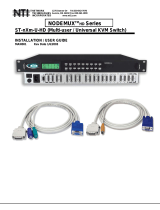
FEATURES AND FUNCTIONS
1. Power Switch- to power up or power down the USB Wizard USB KVM switch
2. Mode Status LEDs- for visual indication of switch operating mode
3. CPU Status LEDs- for visual indication of connection between the user and a specific CPU.
4. CPU Select Switches- push to manually switch to a specific CPU or change the switch operating mode
5. Dipswitches- for configuring cascaded switches
6. Daisy In/Out - for attaching interface cables (REXT-SR-xx) between slave switches and the master switch
7. VIDEO-x- 15HD female connectors- for connecting video cables from CPUs
8. MONITOR- 15HD female connector- for connection of the user video monitor
9. 5VDC- connection jack for the AC adapter
10. CPU x- USB type B female connector-for connection of USB device cable from CPU(s)
11. DEVICES- USB type A female connector- for connection of user USB device(s)
FEATURES AND FUNCTIONS
F E A T U R E S A N D F U N C T I O N S
O N
1 2 3 4 5 6
1
2
3
4 5
6 7 8
M O D E
S C A N
C O M
M A N D
3
2
1
4
5
Rear View of USB Wizard
C P U 8
D E V I C E S
C P U 7 C P U 6 C P U 5 C P U 4 C P U 3 C P U 2 C P U 1
7
1 1
9
8
5 V D C
2 A
-
+
V
I
D
E
O
8
R
V
I
D
E
O
7
V
I
D
E
O
6
V
I
D
E
O
5
V
I
D
E
O
4
V
I
D
E
O
3
V
I
D
E
O
2
V
I
D
E
O
1
M
O
N
I
T
O
R
1 0
D A I S Y
O U T
D A I S Y
I N
6
Front View of USB Wizard

4
INSTALLATION
1. It is not necessary to turn the CPUs or monitors OFF during this installation.
2. Connect the cable from a VGA multi-scan monitor to the 15HD connector labeled “MONITOR” on the USB Wizard
switch. (See Fig. 1 below.)
Figure 1- Connect a VGA multi-scan monitor
3. Connect the male USB type A connector on the keyboard cable to either one of the two USB type A female connectors
labeled "DEVICES" on the rear panel of the USB Wizard.
4. Connect the male USB type A connector on the mouse cable to the remaining USB type A female connector labeled
"DEVICES".
Figure 2- Connect the device(s)
INSTALLATION
C P U 8
D E V I C E S
C P U 7 C P U 6 C P U 5 C P U 4 C P U 3 C P U 2 C P U 1
5 V D C
2 A
-
+
V
I
D
E
O
8
R
V
I
D
E
O
7
V
I
D
E
O
6
V
I
D
E
O
5
V
I
D
E
O
4
V
I
D
E
O
3
V
I
D
E
O
2
V
I
D
E
O
1
M
O
N
I
T
O
R
D A I S Y
O U T
D A I S Y
I N
U S B K e y b o a r d
U S B
M o u s e
U S B T y p e A
M a l e C o n n e c t o r s
U S B T y p e A M a l e
D E V I C E S
U S B
T y p e A
F e m a l e
C P U 8
D E V I C E S
C P U 7 C P U 6 C P U 5 C P U 4 C P U 3 C P U 2 C P U 1
5 V D C
2 A
-
+
V
I
D
E
O
8
R
V
I
D
E
O
7
V
I
D
E
O
6
V
I
D
E
O
5
V
I
D
E
O
4
V
I
D
E
O
3
V
I
D
E
O
2
V
I
D
E
O
1
M
O
N
I
T
O
R
D A I S Y
O U T
D A I S Y
I N
V G A
M u l t i - S c a n
M o n i t o r
1 5 H D M a l e
V i d e o C o n n e c t o r
M
O
N
I
T
O
R
1 5 H D F e m a l e
V i d e o C o n n e c t o r
Rear View of USB Wizard
Rear View of USB Wizard

5
5. When cascading switches, configure dip-switches accordingly (see Tables 1 & 2 on page 8).
6. Power-up the USB Wizard. (See Fig. 3 below.)
Figure 3- Connect the AC adapter
Note: Do not press any port buttons until the PORT 1 LED on the front panel of the switch illuminates.
7. Connect each CPU to the USB Wizard using a USBVEXT-xx-MM video and input device interface cable – REQUIRED
(not supplied). (See Fig. 4 below.)
8. Group the input device and monitor interface cables from each CPU, making sure that cables from the first CPU are
connected to the USB Wizard switch at connectors CPU 1 and VIDEO 1. Cables from the second CPU should
connect to CPU 2 and VIDEO 2 connectors...etc.
Figure 4- Connect each CPU
1 5 H D M a l e
V i d e o C o n n e c t o r
C P U 8
D E V I C E S
C P U 7 C P U 6 C P U 5 C P U 4 C P U 3 C P U 2 C P U 1
5 V D C
2 A
-
+
V
I
D
E
O
8
R
V
I
D
E
O
7
V
I
D
E
O
6
V
I
D
E
O
5
V
I
D
E
O
4
V
I
D
E
O
3
V
I
D
E
O
2
V
I
D
E
O
1
M
O
N
I
T
O
R
D A I S Y
O U T
D A I S Y
I N
U S B T y p e B
F f e m a l e
U S B T y p e A F e m a l e
U S B T y p e A M a l e
U S B V E X T -
x x
- M M
1 5 H D F e m a l e
V i d e o C o n n e c t o r
V
I
D
E
O
1
U S B T y p e B
M a l e
1 5 H D F e m a l e
V i d e o C o n n e c t o r
R e a r V i e w o f W i n d o w s U S B C P U
V i d e o P o r t
I n p u t D e v i c e P o r t
C P U 8
D E V I C E S
C P U 7 C P U 6 C P U 5 C P U 4 C P U 3 C P U 2 C P U 1
5 V D C
2 A
-
+
V
I
D
E
O
8
R
V
I
D
E
O
7
V
I
D
E
O
6
V
I
D
E
O
5
V
I
D
E
O
4
V
I
D
E
O
3
V
I
D
E
O
2
V
I
D
E
O
1
M
O
N
I
T
O
R
D A I S Y
O U T
D A I S Y
I N
5 V D C
A d a p t e r
A C
A D A P T E R
B a r r e l
( I n s i d e
b a r r e l )
( O u t s i d e
b a r r e l )
P o w e r C o n n e c t o r
2 . 1 m m x 5 . 5 m m F e m a l e
5 V D C @ 2 . 5 A O U T P U T
5 V D C
2 A
-
+
Rear View of USB-Wizard
Rear View of USB Wizard

6
Power-Up Sequence
• The USB Wizard can be powered at any time.
• The CPUs can be powered at any time although if a CPU needs a keyboard and/or mouse at power-ON it should be powered
after connecting to and powering-ON the USB Wizard.
• USB input devices (keyboard and mouse) can be hot plugged to and from the USB Wizard switch at any time.
If the security option is enabled (see page 12 for details on the "Security Option"), when the USB Wizard is powered up the
user will be prompted for a username and password to continue. If the security option is not enabled the monitor will display the
desktop image for the connected CPU and the user can continue with normal operation of the connected CPU.
Limitations
• Only USB input device or hub cables can be connected to the USB Wizard at the USB Type A female ports labeled
"DEVICES". (See Features and Functions on page 3, item 11.)
• A USB hub (single or multi-port) can be used provided only USB input devices (except for MAC keyboards) are plugged into
it.
• No additional hubs may be connected (as in a daisy-chain) to the hub that is directly connected to the USB Wizard.
• USB MAC keyboards with USB Type A female ports built into them are designed as hubs and must be treated as such with
respect to the USB Wizard. As a result, USB MAC keyboards cannot be connected to a multi-port hub or other
MAC keyboards connected directly to the switch.
• Only a USB Windows or SUN keyboard or USB mouse may be connected to the USB port on a USB MAC keyboard
• A maximum of 8 input devices may be connected to the USB Wizard either directly or through hubs.
See Fig. 5 for some examples of input device combinations that can and cannot be used with the USB Wizard.
Figure 5- Compatible and incompatible device combinations
U S B W i n d o w s K e y b o a r d
U S B
M o u s e
U S B T y p e A
M a l e C o n n e c t o r s
U S B M A C K e y b o a r d
U S B
M o u s e
U S B
M o u s e
U S B
M o u s e
U S B W i n d o w s K e y b o a r d
U S B W i n d o w s K e y b o a r d
O K
O K
O K
U S B M A C K e y b o a r d
U S B M A C K e y b o a r d
N O
2 U S B h u b s i n s e r i e s
( D a i s y - C h a i n e d )
N O
T y p i c a l I n s t a l l a t i o n - 1 K e y b o a r d , 1 M o u s e
O p t i o n a l - M u l t i p l e k e y b o a r d s a n d m i c e
O p t i o n a l - M A C U S B k e y b o a r d a n d m o u s e
U S B
H u b

7
CASCADING
The USB Wizard can be cascaded as shown in Fig. 6 below. If USB Wizard switches are being cascaded, configure
the dip-switches accordingly (see Tables 1 and 2 on page 8).
Configuration
All units are configured using the 6-position dip switch (located on the front of each unit) according to the tables on page 8 (1 & 2).
Cascaded Installation
a. Configure each dip switch as per the tables on page 8 before proceeding.
b. Using the 15HD video cable ends of a USBVEXT-xx-MM cable, connect the USB Wizard slave's MONITOR port to the master’s
VIDEO 1 port.
c. Using the USB ends of the same USBVEXT-xx-MM cable, connect one of the USB slave’s USB DEVICES ports to the
master’s CPU 1 port.
Note: Only one of the two ports labeled DEVICES on a slave needs to be used in order for cascading to work.
d. Repeat step b. & c. for each additional slave, keeping in mind that each slave will connect to the next available master’s
port (i.e. Slave #2 to master’s VIDEO 2 & CPU 2, etc.) See Fig. 7 on page 8.
e. With a RMT extension cable, connect the master’s DAISY OUT port to slave #2’s DAISY IN port. Then connect slave #2’s
DAISY OUT to slave #3's DAISY IN. Continue until all slaves are connected together.
Figure 6- Connections for Cascading
.
CASCADING
( s l a v e u n i t 1 )
( s l a v e u n i t 2 )
( s l a v e u n i t 3 )
( m a s t e r u n i t )
R E X T - S R - x x
R E X T - S R - x x
R E X T - S R - x x
U S B - V E X T - x x M M
U S B V E X T - x x - M M
U S B
C P U
U S B
C P U
U S B
C P U
U S B
C P U
U S B
C P U
U S B
C P U
U S B
C P U
U S B
C P U
U S B V E X T - x x - M M
U S B V E X T - x x - M M
U S B V E X T - x x - M M
U S B - V E X T - x x M MU S B - V E X T - x x M M
USB Wizard USB Wizard USB Wizard
USB Wizard

8
Front Panel Configuration Switches
Table 1 * (default settings)
Switch SW1 SW5 SW6
STAND-ALONE SWITCH OFF* OFF* OFF*
SLAVE ON OFF OFF
MASTER W/4-PORT SLAVES OFF OFF ON
MASTER W/8-PORT SLAVES OFF ON OFF
MASTER W/16-PORT SLAVES OFF ON ON
Table 2 * (default settings) Master & Slave dip switch 2-4 Settings
SW2 SW3 SW4 Master with- Slave Setting
OFF*
OFF*
OFF* No Slave Attached N/A
OFF OFF OFF 1 Slave attached Slave #1
OFF OFF ON 2 Slaves attached Slave #2
OFF ON OFF 3 Slaves attached Slave #3
OFF ON ON 4 Slaves attached Slave #4
ON OFF OFF 5 Slaves attached Slave #5
ON OFF ON 6 Slaves attached Slave #6
ON ON OFF 7 Slaves attached Slave #7
ON ON ON 8 Slaves attached Slave #8
Note: All USB Wizard switches must be powered OFF during dip switch configuration
Figure 7- Master-to-Slave Device Cable Connections
Limitations
¾ All switches used as slaves must be the same size (all 8 port).
¾ Up to 8 slaves be connected to form a maximum system size of 64 ports.
¾ Slaves must be added to the master in order (slave #1 to master’s port 1, slave #2 to master’s port 2, etc).
Note: Master Port 1 (with an 8-port Slave connected to it) will become ports 1-8. Master Unit Port
2 (with a second 8-port Slave Unit connected) will become port numbers 9-16.
¾ All USB Wizard switches must be powered OFF during dip switch configuration.
These switch settings (Table 2) enable the slave to
establish its identity (i.e. location in the group) to the
Master.
Side Note: In a Master, the same switches are used to
configure the Master for how many slaves are attached
to it.
C P U 8
D E V I C E S
C P U 7 C P U 6 C P U 5 C P U 4 C P U 3 C P U 2 C P U 1
5 V D C
2 A
-
+
V
I
D
E
O
8
R
V
I
D
E
O
7
V
I
D
E
O
6
V
I
D
E
O
5
V
I
D
E
O
4
V
I
D
E
O
3
V
I
D
E
O
2
V
I
D
E
O
1
M
O
N
I
T
O
R
D A I S Y
O U T
D A I S Y
I N
C P U 8
D E V I C E S
C P U 7 C P U 6 C P U 5 C P U 4 C P U 3 C P U 2 C P U 1
5 V D C
2 A
-
+
V
I
D
E
O
8
R
V
I
D
E
O
7
V
I
D
E
O
6
V
I
D
E
O
5
V
I
D
E
O
4
V
I
D
E
O
3
V
I
D
E
O
2
V
I
D
E
O
1
M
O
N
I
T
O
R
D A I S Y
O U T
D A I S Y
I N
C P U 8
D E V I C E S
C P U 7 C P U 6 C P U 5 C P U 4 C P U 3 C P U 2 C P U 1
5 V D C
2 A
-
+
V
I
D
E
O
8
R
V
I
D
E
O
7
V
I
D
E
O
6
V
I
D
E
O
5
V
I
D
E
O
4
V
I
D
E
O
3
V
I
D
E
O
2
V
I
D
E
O
1
M
O
N
I
T
O
R
D A I S Y
O U T
D A I S Y
I N
S L A V E # 2
U S B V E X T - x x - M M
S L A V E # 1
U S B V E X T - x x - M M
M A S T E R

9
USING THE
Once the USB Wizard switch is properly connected, the USB Wizard will enable a connection to be made between the
CPUs attached to its VIDEO and CPU ports and the monitor and input devices attached to the MONITOR and DEVICES ports.
The LEDs on the control panel of the USB Wizard will illuminate depending on which port (and corresponding CPU) is being
connected to the monitor and input devices.
The USB Wizard can be controlled by three methods:
• front control panel using touch-switches and LEDs
• keyboard control through Command Mode
• mouse clicks from within some menus of OSD Command Mode (optional).
Front Panel Control
There is a touch-switch and LED on the front panel of the USB Wizard for each CPU the switch will connect the monitor
and input devices to. Pressing any touch-switch on the front panel of the USB Wizard will connect the corresponding CPU
to the monitor and input devices.
Holding down any front panel touch-switch for more than 2 seconds will cause the USB Wizard to cycle through
all modes of operation including COMMAND, SCAN, and NORMAL (described below and on page 11). The two
MODE LEDs on the front panel indicate which mode is selected. Release the touch-switch when the LEDs indicate the desired
mode. When no mode LEDs are illuminated the user is in Normal Mode controlling directly the CPU to which the user is
connected through the USB Wizard.
Keyboard Control
Keyboard control of the USB Wizard can be achieved using either of two methods:
• Basic Command Mode- operated strictly by using keyboard commands as instructed below. Basic Command Mode
is only applicable if the OSD option is not built into the switch.
• OSD Command Mode (optional)- operated using the keyboard and mouse in conjunction with OSD menus superimposed
onto the monitor. If OSD is built in, use the menus as instructed on page 11.
By pressing <Ctrl> + < ` > (accent key), the user can enter Command Mode (either Basic, or OSD). Once in Command
Mode, typing a series of commands will cause the USB Wizard to connect the user to any one CPU connected to the switch.
Pressing the <Esc> key will exit Command Mode.
MODES OF OPERATION
Basic Command Mode
In order to control the USB Wizard with the keyboard connected, Command Mode must be enabled. To enter Command Mode
from the keyboard:
Press
`
+
Ctrl
~
(ACCENT
KEY)
`
USING THE USB WIZARD KVM SWITCH
MODES OF OPERATION

10
OSD superimposes a menu system on the user’s video screen with a list of all connected CPUs. OSD allows CPUs to be named
(with up to 12-character names). OSD then allows selection of CPUs by that name. Connected CPUs can be listed by name or
by port number. OSD Search Mode enables the user to type in the first few characters of the CPU's name and the OSD will locate
it. Help screens assist with all OSD functions.
Security Option
The security option of the OSD Control enables an administrator to control access to CPU ports for each user. Up to 24 users
can be created. These users have controlled access to any CPU. Only the administrator can activate or deactivate the security
features. Security can be activated from the Maintenance Mode menu (page 17) with a successful administrator login for
verification purposes. Furthermore, the administrator can set a maximum idle time value after which the current user will be
logged out and the login screen displayed. This time out does not function while the OSD is active. The current security status,
idle time out, and scan dwell time are all saved and will be restored whenever power to the switch is cycled OFF, then ON. To
reset the administrator's password call Lightwave Communications and have the device serial number of the USB Wizard available.
Enabling the Security Feature
To enable the security feature the administrator must first enter Command Mode from the keyboard using the sequence
<Ctrl> + <`> (accent key). The OSD menu will automatically appear on the monitor in addition to illuminating the Command Mode
indicator LED on the USB Wizard. This provides a visual way to control the USB Wizard using the keyboard and mouse.
The administrator , when setting the USB Wizard up for the first time, may want to proceed directly to the
ADMINISTRATION Mode by typing <CTRL> +<M> , then <A>, and then <Y>.
The factory settings are:
• default user name = ADMINISTRATOR
• default password = ADMINISTRATOR
Note: The user name for the administrator cannot be
changed from "ADMINISTRATOR".
Once logged-in, follow the instructions on page 12 for
setting up users and changing the password. Once the
password is setup, if it is lost or forgotten the administrator
will have to contact Lightwave for assistance on clearing the
password and set it up again. Within the Administration
Mode the administrator can setup each of the users and the
limitations of their use of the individual CPUs attached to
the switch.
Figure 8- Administrator Login screen
When a standard user powers up the system a security screen will appear if security has been enabled by the
administrator. The user will need to login to the switch by following the instructions on page 12 for the USER LOGIN. If the
user does not know the appropriate user name and password (setup by the administrator), contact the switch administrator for this
information. Once logged-in a user can follow the Command Mode functions described on page 14 to control the switch within
the limitations as determined by the administrator.
OSD CONTROL

11
User Login Mode
User login mode requires a user to login with a user name and password from the list created by the administrator. This mode will
also disable use of the front panel until the user logs in.
Function: Keystroke:
Adds a character to the
user name/password
Removes previous character
from the user name/password
Submit user name/password
Exit USER LOGIN and return
to previous mode. This function
is only available if security is
not currently active.
Figure 9- User Login screen
ADDITIONAL MODES AVAILABLE WITH SECURITY
The three modes that follow are only available if the administrator is logged in.
Administration Mode
To enter the Administration Mode menu press <A>
from the Maintenance Mode menu (page 10).
Administration Mode allows the administrator to use
the following functions:
Function: Keystroke:
Change the administrator’s
password
Disable security
Update User Name List
Figure 10- Administration Mode menu
Toggle Language in menus
between English and Italian
Selects the idle time in minutes
Exit Administration Mode and
return to previous mode
Esc
Enter
A-Z
0-9
(Type any alphabetical or numeric character)
Backspace
If the password submitted is incorrect, the user will not be able to proceed.
If the password submitted is correct, the user will proceed to Normal Mode.
Esc
S
C
U
ADDITIONAL MODES AVAILABLE WITH SECURITY
L
T
-
-
(xxx from 000 to 255. i.e. T002
would set the time-out period
for 2 minutes. 000 will disable it)
-
(0-2)
x
(0-9)
x
(0-9)
x

12
Administrator Password
To change the administrator password press <C> from the
Administration Mode menu.
The administrator is able to change the administrator
password as needed (see Fig. 11). Two edit fields are
available, one for password, the other for verify password.
The password can be up to 13 characters in length.
Note: The default password for the administrator is
ADMINISTRATOR.
Figure 11- Administrator password change
Function: Keystroke:
Add character to password string
or verify password string
Delete previous character in
edited string
Save new password.
Return to Administration Mode
User Name List
To enter the User Name List press <U> from the Administration Mode menu.
The User Name List displays the list of users and provides control for adding new users (up to 24), changing or assigning user
passwords, and changing access rights for any given user. User names may be up to 12 characters long, may not contain
spaces, and are not case sensitive. Passwords may be up to 15 characters long, may not contain spaces, and are case sensitive.
Function: Keystroke:
Edit the highlighted user’s
System Access rights
Enter Edit Mode to add/change/
remove users
Change the highlighted user’s
password
Exit the USER NAME LIST and
return to previous mode
Figure 12- User Name List screen
Esc
E
Ctrl
+
A
Ctrl
+
P
Ctrl
+
Esc
Enter
(If Password string and Verify Password string
are different, this command will have no effect,
enabling the administrator to correct the password)
Backspace
Shift
or
A-Z
(Type any upper or lower case
alphabetical or numeric character)
+
A-Z
0-9

13
System Access List
To enter the System Access List press <Ctrl> + <A> from the User Name List menu.
The System Access List displays a list of numbers representing the ports so the administrator can change access rights to the
ports for the selected user. The user’s name is displayed at the top of the access list. The mouse is used to change access rights
by clicking on a given number to toggle a port’s status. A user that has access to a port can connect to that port and control the
CPU connected to that port when in Normal Mode.
Function: Keystroke:
Save the changes to the access
list and return to previous mode
Exit the System Access List without
saving and return to previous mode.
Figure 13- System Access List screen
USER ACCESS FUNCTIONS
INTRODUCTION
The OSD menu enables a user to name the CPUs connected to the USB Wizard and connect to them using that name from a
single keyboard and mouse. The OSD is positioned on the user's monitor, displaying 8 CPU names at a time. The screen can be
used for switching as well as editing the CPUs’ names. Through the OSD menu, the user can operate the USB Wizard to
have the switch cycle through 2 extended modes of operation: COMMAND and SCAN . Two LEDs on the front panel indicate
when these modes are enabled.
OSD Command Mode
When entering the Command Mode from the keyboard using the <Ctrl> + <`> (accent key), the OSD menu will automatically
appear on the monitor in addition to illuminating the COMMAND indicator LED on the USB KVM switch. This provides a visual
way to control the USB Wizard.
The list below describes the OSD Command functions available from
the keyboard after entering Command Mode and while the COMMAND
LED is illuminated:
Function: Keystroke:
Select the previous port
Select the next port
Enable/disable Scan Mode
Figure 14- Command Mode screen
Enter Edit Mode
Esc
Enter
S
Ctrl
+
E
Ctrl
+
USER ACCESS FUNCTIONS

14
OSD Command Mode (Cont'd)
Function: Keystroke:
Enter Maintenance Mode
Sets scan time-out on
each port
Selects a specific port
Enters Search Mode and adds a character
to search string and selects the CPU’s
name that matches best.
Selects the first port on the switch
Selects the last port on the switch
Display Help Menu
Switch to a selected port
Figure 15- More Command Mode Features
Exit OSD Command Mode
The mouse can also be used to control the USB Wizard within the Command Mode menu.
• The mouse cursor can be moved to the Scan, Help, and Exit fields where the user can then click on the left mouse
button to perform that function.
• Ports listed on the screen can be selected by moving the cursor onto that port and clicking. Clicking twice on a
selected port will switch to that port and exit Command Mode.
• To change the displayed ports on the screen simply click on the up and down arrows located to the right of the port
names displayed.
F1
End
Enter
Home
Esc
A-Z
0-9
(Type any alphabetical or numeric character)
Note: The user must exit Command Mode to type to a CPU.
To exit Command Mode, either hold down any touch-switch on the front
p
anel for more than 2 seconds, OR press <ESC> on the keyboard.
Press <CTRL> while in the Command Mode menu
to display the Edit, Maintenance, Port, and Timeout
control features.
P
-
-
(Pxx would be P01, P02, etc.)
(0-9)
x
(0-9)
x
Ctrl
+
T
-
-
(xxx from 002 to 255. ie. t002
would set the time-out period
for 2 seconds)
-
(0-2)
x
(0-9)
x
(0-9)
x
Ctrl
+
M
Ctrl
+

15
Scan Mode
To activate Scan Mode press <Ctrl> + <S> from the Command Mode menu.
When in Scan Mode the switch scans to each port with a CPU powered-ON. (The SCAN LED on the front panel will illuminate and
remain ON while in Scan Mode. ) The port with the CPU powered-ON remains active while in use until it becomes idle for the
configured dwell time (default time-out period is 5 seconds) before switching to the next powered-ON CPU port. See Command
Mode section above for configuring the scan dwell time.
Note: The keyboard and mouse must remain idle for the full scan dwell time before the switch selects the next active
port.
Note: The scan dwell time set by the user only effects that user and has no effect on other switch users.
Normal Mode
When the USB Wizard is not in Command or Scan mode and all of the USB KVM switch mode LEDs are OFF, the
user is in Normal Mode, controlling the CPU to which the user is connected through the USB Wizard.
Edit Mode
To activate Edit Mode press <Ctrl> + <E> from the Command Mode menu.
Edit Mode enables the user to modify the names of the CPUs connected to the switch. Names of CPUs can be up to 12
characters in length. When in Edit Mode, multiple keystroke combinations are not valid (<Shift>+P, <Ctrl>+P, <Alt>+ P, and P will
all type a “P” to the display - lower case letters cannot be typed).
Function: Keystroke:
Move cursor one position
to the right
Move cursor one position
to the left
Move cursor to the
previous port
Move cursor to the
next port
Selects the first port on
the switch
Figure 16- Edit Mode screen
Selects the last port on
the switch
Toggles between insert
and overstrike
Erase current character
Erase previous character
When finished making changes in Edit Mode, press <Enter> and a prompt will appear to press either <Y> to save the changes or
<N> to continue making changes without saving the changes just made. If the <Esc> key is pressed instead of <Enter>, all
changes made will be ignored and the display will return to the previous menu.
Home
End
Insert
(The character either gets inserted and the remainder of the name
gets shifted to the right, OR the current character gets overwritten.)
Delete
Backspace

16
Search Mode
To enter Search Mode, type any alphabetical or numeric character when the Command Mode menu is on the monitor.
Search Mode enables the user to enter and maneuver
through a list of CPU names. The CPU name best
matching the characters typed is selected. The list of
CPUs may also be searched for a specific (or similar)
name. The following commands are valid when the
search option has been invoked from Command Mode.
Function: Keystroke:
Erase previous character
in search name
Figure 17- Search Mode screen
Add a character to the search
string and select the best
matching CPU name
Exit Search Mode, return to
Command Mode
Switch to selected port
Maintenance Mode
To enter Maintenance Mode press <Ctrl>+<M> from the Command Mode menu.
Maintenance Mode enables a user to customize the On Screen Display to their requirements.
Function: Keystroke:
Reset all of the port names
Toggle between numeric and
alphabetic listing of ports
Move On Screen Display (OSD)
menu up on monitor
Move OSD menu down on
monitor
Move OSD menu to the right
Figure 18- Maintenance Mode screen
Backspace
A-Z
0-9
(Type any alphabetical or numeric character)
Esc
Enter
R
L
/