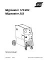
ESAB Migmaster 253 User manual
- Category
- Welding System
- Type
- User manual
This manual is also suitable for

0349 300 050 Valid for serial no. 421/402/429--xxx--xxxx071024
Migmaster 173/203
Migmaster 253
S
e
r
v
i
c
e
m
a
n
u
a
l

-- 2 --TOCe
READ THIS FIRST 3. . . . . . . . . . . . . . . . . . . . . . . . . . . . . . . . . . . . . . . . . . . . . . . . . . . . . . . . . . . . . . . . .
INTRODUCTION 3. . . . . . . . . . . . . . . . . . . . . . . . . . . . . . . . . . . . . . . . . . . . . . . . . . . . . . . . . . . . . . . . . . .
TECHNICAL DATA 4. . . . . . . . . . . . . . . . . . . . . . . . . . . . . . . . . . . . . . . . . . . . . . . . . . . . . . . . . . . . . . . . .
WIRING DIAGRAM, Migmaster 173 / 203 6. . . . . . . . . . . . . . . . . . . . . . . . . . . . . . . . . . . . . . . . . . . . .
Component description 6. . . . . . . . . . . . . . . . . . . . . . . . . . . . . . . . . . . . . . . . . . . . . . . . . . . . . . . . . .
Migmaster 173, 230V 8. . . . . . . . . . . . . . . . . . . . . . . . . . . . . . . . . . . . . . . . . . . . . . . . . . . . . . . . . . . .
Migmaster 203, 230/208V 9. . . . . . . . . . . . . . . . . . . . . . . . . . . . . . . . . . . . . . . . . . . . . . . . . . . . . . . . .
Migmaster 203, 230/208V (diagram valid for S/N up to 4024460302) 10. . . . . . . . . . . . . . . . . .
Migmaster 203, relay KIT (gas valve, spool gun) connections 11. . . . . . . . . . . . . . . . . . . . . . .
DESCRIPTION OF OPERATION 12. . . . . . . . . . . . . . . . . . . . . . . . . . . . . . . . . . . . . . . . . . . . . . . . . . . . .
AP1 Control board 12. . . . . . . . . . . . . . . . . . . . . . . . . . . . . . . . . . . . . . . . . . . . . . . . . . . . . . . . . . . . . .
AP1:1 Power supply 14. . . . . . . . . . . . . . . . . . . . . . . . . . . . . . . . . . . . . . . . . . . . . . . . . . . . . . . . . . . . . .
AP1:2 Reference circuit 14. . . . . . . . . . . . . . . . . . . . . . . . . . . . . . . . . . . . . . . . . . . . . . . . . . . . . . . . . . .
AP1:3,4,5 Start / Stop, Thermal overload, Spot welding 15. . . . . . . . . . . . . . . . . . . . . . . . . . . . . . . .
AP1:6 Burnback time 16. . . . . . . . . . . . . . . . . . . . . . . . . . . . . . . . . . . . . . . . . . . . . . . . . . . . . . . . . . . . .
AP1:7 Control amplifier and pulse width modulator 16. . . . . . . . . . . . . . . . . . . . . . . . . . . . . . . . . . . .
AP1:8,9 Motor driving / braking 17. . . . . . . . . . . . . . . . . . . . . . . . . . . . . . . . . . . . . . . . . . . . . . . . . . . . .
AP1 -- Migmaster 173 / 203 component positions 18. . . . . . . . . . . . . . . . . . . . . . . . . . . . . . . . . . . . .
WIRING DIAGRAM, Migmaster 253 19. . . . . . . . . . . . . . . . . . . . . . . . . . . . . . . . . . . . . . . . . . . . . . . . . .
Component description 19. . . . . . . . . . . . . . . . . . . . . . . . . . . . . . . . . . . . . . . . . . . . . . . . . . . . . . . . . .
Migmaster 253, 230/208V 21. . . . . . . . . . . . . . . . . . . . . . . . . . . . . . . . . . . . . . . . . . . . . . . . . . . . . . . . .
Migmaster 253, 230/208V (diagram valid for S/N up to 429 449 0050) 22. . . . . . . . . . . . . . . .
Migmaster 253, relay KIT (gas valve, spool gun) connections 23. . . . . . . . . . . . . . . . . . . . . . .
DESCRIPTION OF OPERATION 24. . . . . . . . . . . . . . . . . . . . . . . . . . . . . . . . . . . . . . . . . . . . . . . . . . . . .
AP1 Control board 24. . . . . . . . . . . . . . . . . . . . . . . . . . . . . . . . . . . . . . . . . . . . . . . . . . . . . . . . . . . . . .
AP1:1 Power supply 24. . . . . . . . . . . . . . . . . . . . . . . . . . . . . . . . . . . . . . . . . . . . . . . . . . . . . . . . . . . . . .
AP1:2 Start / Stop 24. . . . . . . . . . . . . . . . . . . . . . . . . . . . . . . . . . . . . . . . . . . . . . . . . . . . . . . . . . . . . . . .
AP1:3 Spot welding 25. . . . . . . . . . . . . . . . . . . . . . . . . . . . . . . . . . . . . . . . . . . . . . . . . . . . . . . . . . . . . . .
AP1:4 Wire feed speed 25. . . . . . . . . . . . . . . . . . . . . . . . . . . . . . . . . . . . . . . . . . . . . . . . . . . . . . . . . . . .
AP1:5 Motor driving / braking 26. . . . . . . . . . . . . . . . . . . . . . . . . . . . . . . . . . . . . . . . . . . . . . . . . . . . . .
AP1:6 Burnback time, contactor, gas valve 27. . . . . . . . . . . . . . . . . . . . . . . . . . . . . . . . . . . . . . . . . . .
AP1:7 Thermal overload cutout 27. . . . . . . . . . . . . . . . . . . . . . . . . . . . . . . . . . . . . . . . . . . . . . . . . . . . .
AP1 -- Migmaster 253 component positions 28. . . . . . . . . . . . . . . . . . . . . . . . . . . . . . . . . . . . . . . . . .
AR Control board 29. . . . . . . . . . . . . . . . . . . . . . . . . . . . . . . . . . . . . . . . . . . . . . . . . . . . . . . . . . . . . . .
AR component positions 29. . . . . . . . . . . . . . . . . . . . . . . . . . . . . . . . . . . . . . . . . . . . . . . . . . . . . . . . . . .
AR diagram 29. . . . . . . . . . . . . . . . . . . . . . . . . . . . . . . . . . . . . . . . . . . . . . . . . . . . . . . . . . . . . . . . . . . . . .
SERVICE INSTRUCTIONS 30. . . . . . . . . . . . . . . . . . . . . . . . . . . . . . . . . . . . . . . . . . . . . . . . . . . . . . . . . .
What is ESD? 30. . . . . . . . . . . . . . . . . . . . . . . . . . . . . . . . . . . . . . . . . . . . . . . . . . . . . . . . . . . . . . . . . . .
Thermal switch (thermostat) replacement procedure 30. . . . . . . . . . . . . . . . . . . . . . . . . . . . . . .
INSTRUCTIONS 31. . . . . . . . . . . . . . . . . . . . . . . . . . . . . . . . . . . . . . . . . . . . . . . . . . . . . . . . . . . . . . . . . . .
SAFETY 31. . . . . . . . . . . . . . . . . . . . . . . . . . . . . . . . . . . . . . . . . . . . . . . . . . . . . . . . . . . . . . . . . . . . . . . .
INSTALLATION 32. . . . . . . . . . . . . . . . . . . . . . . . . . . . . . . . . . . . . . . . . . . . . . . . . . . . . . . . . . . . . . . . . . . .
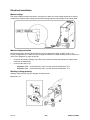
Placing 32. . . . . . . . . . . . . . . . . . . . . . . . . . . . . . . . . . . . . . . . . . . . . . . . . . . . . . . . . . . . . . . . . . . . . . . . .
Assembly of components 32. . . . . . . . . . . . . . . . . . . . . . . . . . . . . . . . . . . . . . . . . . . . . . . . . . . . . . . .
Electrical installation 33. . . . . . . . . . . . . . . . . . . . . . . . . . . . . . . . . . . . . . . . . . . . . . . . . . . . . . . . . . . .
Mains power supply 34. . . . . . . . . . . . . . . . . . . . . . . . . . . . . . . . . . . . . . . . . . . . . . . . . . . . . . . . . . . . .
OPERATION 35. . . . . . . . . . . . . . . . . . . . . . . . . . . . . . . . . . . . . . . . . . . . . . . . . . . . . . . . . . . . . . . . . . . . . . .
Switching--on and overheating protection 36. . . . . . . . . . . . . . . . . . . . . . . . . . . . . . . . . . . . . . . . .
Operation 36. . . . . . . . . . . . . . . . . . . . . . . . . . . . . . . . . . . . . . . . . . . . . . . . . . . . . . . . . . . . . . . . . . . . . . .
MIG process set--up guide 36. . . . . . . . . . . . . . . . . . . . . . . . . . . . . . . . . . . . . . . . . . . . . . . . . . . . . . .
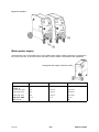
Setting the wire feed pressure 40. . . . . . . . . . . . . . . . . . . . . . . . . . . . . . . . . . . . . . . . . . . . . . . . . . .
MAINTENANCE 40. . . . . . . . . . . . . . . . . . . . . . . . . . . . . . . . . . . . . . . . . . . . . . . . . . . . . . . . . . . . . . . . . . . .
Inspection and cleaning 40. . . . . . . . . . . . . . . . . . . . . . . . . . . . . . . . . . . . . . . . . . . . . . . . . . . . . . . . .
FAULT TRACING 41. . . . . . . . . . . . . . . . . . . . . . . . . . . . . . . . . . . . . . . . . . . . . . . . . . . . . . . . . . . . . . . . . .

-- 3 --TOCe
ORDERING OF SPARE PARTS 41. . . . . . . . . . . . . . . . . . . . . . . . . . . . . . . . . . . . . . . . . . . . . . . . . . . . . .
NOTES 42. . . . . . . . . . . . . . . . . . . . . . . . . . . . . . . . . . . . . . . . . . . . . . . . . . . . . . . . . . . . . . . . . . . . . . . . . . .

Edition 071024
-- 4 --
1sM1725
READ THIS FIRST
Maintenance and repair work should be performed by an experienced person, and
electrical work only by a trained electrician. Use only recommended replacement parts.
This service manual is intended for use by technicians with electrical/electronic training for
help in connection with fault--tracing and repair.
Use the wiring diagram as a form of index for the description of operation. The circuit
board is divided into numbered blocks, which are described individually in more detail in
the description of operation. All component names in the wiring diagram are listed in the
component description.
This manual contains details of all design changes that have been made up to and
including October 2007.
The Migmaster 173/203/253 are designed and tested in accordance with international
and European standard IEC/EN 60974--1 and EN 60974--10.
On completion of service or repair work, it is the responsibility of the person(s) etc.
performing the work to ensure that the product does not depart from the requirements
of the above standard.
INTRODUCTION
Migmaster 173/203/253 are step controlled power sources in a compact design,
intended for welding with solid steel, stainless steel or aluminium wire as well as
tubular wire with or without shielding gas.
The possibility of welding with homogeneous wire/shielding gas and welding with
gasless tubular wire is obtained by switching the + and -- connections on the
switching terminal by the wire feed unit.
Do not dispose of electrical equipment together with normal waste!
In observance of European Directive 2002/96/EC on Waste Electrical and Electronic
Equipment and its implementation in accordance with national law, electrical equipment
that has reached the end of its life must be collected separately and returned to an
environmentally compatible recycling facility. As the owner of the equipment, you should
get information on approved collection systems from our local representative.
By applying this European Directive you will improve the environment and human health!

Edition 071024
-- 5 --1sM1725
TECHNICAL DATA
Migmaster 173
Voltage 230V, 1∼ 50/60Hz
Permissible load at
100% duty cycle 76A
60 % duty cycle 98A
20 % duty cycle 170A
Setting range (DC) 30A/15.5V--170A/18.5V
Open circuit voltage 19.5--35.0V
Open circuit power 160W
Power factor at max load 0,90
Control voltage 42V, 50/60Hz
Wire feed speed 40--670ipm (1.0--17m/min)
Burnback time 0.02--0.25s
Spot welding 0.2--2.5s
Welding gun connection EURO
Wire dimension range
Fe
Al
FCW
.023--.030” (0.6--0.8mm)
.035--.040” (0.9--1.0mm)
.030” (0.8mm)
Max diameter/weight
of wire bobin
12” (300mm)/33lb (15kg)
Dimensions lxwxh 33x16x28” (860x420x730mm)
Weight 130lb (59kg)
Operating temperature 14÷104F (--10 ÷ +40
o
C)
Enclosure class IP 23
Application classifica-
tion
Migmaster 203 Migmaster 253
Voltage 230V, 1∼ 50/60Hz 230V, 1∼ 50/60Hz
Permissible load at
100% duty cycle 90A 110A
60 % duty cycle 115A 140A
20 % duty cycle 200A 250A
Setting range (DC) 30A/15.5V--200A/22V 40A/16.0V--250A/23V
Open circuit voltage 18--38V 19.5--43V
Open circuit power 140W 200W
Power factor at max load 0.83 0.92
Control voltage 42V, 50/60Hz 42V, 50/60Hz
Wire feed speed 40--670ipm (1.0--17m/min) 75--748ipm (1.9--19m/min)

Edition 071024
-- 6 --
1sM1725
Burnback time
0.02--0.25s 0--0.25s
Spot welding 0.2--2.5s 0.2--2.5s
Welding gun connection EURO EURO
Wire dimension range
Fe
Al
FCW
.023--.045” (0.6--1.1mm)
.035--.040” (0.9--1.0mm)
.030--.045” (0.8--1.1mm)
.023--.045” (0.6--1.1mm)
.040--3/64” (1.0--1.2mm)
.030--.045” (0.8--1.1mm)
Max diameter/weight
of wire bobin
12” (300mm)/33lb (15kg) 12” (300mm)/33lb (15kg)
Dimensions lxwxh 33x16x28” (860x420x730mm) 33x16x28” (860x420x730mm)
Weight 150lb (68kg) 216lb (98kg)
Operating temperature 14÷104F (--10 ÷ +40
o
C) 14÷104F (--10 ÷ +40
o
C)
Enclosure class IP 23 IP 23
Application classifica-
tion
Duty cycle
The duty cycle refers to the time as a percentage of a ten--minute period that you can weld at a cer-
tain load without overloading.
Enclosure class
The IP code indicates the enclosure class, i. e. the degree of protection against penetration by solid
objects or water. Equipment marked IP23 is designed for indoor and outdoor use.
Application class
The symbol indicates that the power source is designed for use in areas with increased
electrical hazard.

Edition 071024
-- 7 --1sM1725
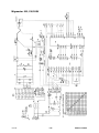
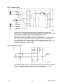
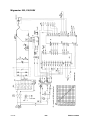
WIRING DIAGRAM, Migmaster 173 / 203
Component description
WARNING !
STATIC ELECTRICITY can damage circuit
boards and electronic components.
S
SS
S Observe precautions for handling electrostatic
sensitive devices.
S
SS
S Use proper static--proof bags and boxes.
ESD
AP1 Circuit board
AP2 Digital instrument, accessory
C1, C2, CVS Capacitor 0,1uF/250V
EV1 Fan
KM1 Contactor 42V, 50--60Hz
L1 Inductor
L2, L3 Ferrite core
LF1 Lamp, white, On/Off, 230V
M1 Feed unit motor
QF1 Switch, ON/OFF
QF2 Switch, 8--step welding voltage selector for C170
Switch, 12--step welding voltage selector for C200
RO Resistor 15Ω/20W
RVS Resistor
RP1 Potentiometer, wire feed speed
RP2 Potentiometer with switch, spot welding
RI Shunt, accessory
RL Resistor
ST1 Thermal oveload cutout, operates at 130
o
C. The cutout is mounted at
the cooling fins of the diode bridge.
TC1 Control transformer
TC2 Transformer for CO2 heater, accessory
TC3 Transformer for digital instrument, accessory
TM1 Main transformer
V1 Diode bridge
VH LED yellow indication, thermal overload

Edition 071024
-- 8 --
1sM1725
XTP Main welding current contact, single -- pole
XT1, XT4 Terminal block
YV1 Gas valve

Edition 071024
-- 9 --1sM1725
Migmaster 173, 230V

Edition 071024
-- 10 --
1sM1725
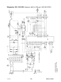
Migmaster 203, 230/208V

Edition 071024
after delivery machine was
modified according to diagram
on page 12
-- 11 --1sM1725
Migmaster 203, 230/208V (diagram valid for S/N up to 4024460302)

Edition 071024
-- 12 --
1sM1725
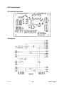
Migmaster 203, relay KIT (gas valve, spool gun) connections

Edition 071024
-- 13 --1sM1725
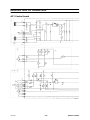
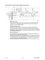
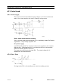
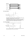
DESCRIPTION OF OPERATION
AP1 Control board
clka1e03

Edition 071024
-- 14 --
1sM1725
clka1e04

Edition 071024
-- 15 --1sM1725
AP1:1 Power supply
clka1e06
Transformer TC1 supplies indicating lamp HL1 and rectifier bridge BR1
with 27 V AC. The unsmoothed DC output from BR1 is smoothed by capacitors
C5 and C25 to produce an open--circuit voltage of 38 V ”10%.
This provides the power supply for the wire feeder motor.
Connections T6 and T7 supply 20 V AC from transformer TC1 to diodes D18 --
D21. The rectified voltage is about 24 V in the fan--cooled machines and
somewhat higher in the 3--phase LKA 180. This supply powers fan EV1 in the
fan--cooled machines. Voltage regulator VR1 is supplied via diode D1 to
provide a regulated 15 ᐔ0.6 V supply.
AP1:2 Reference circuit
clka1e07
Potentiometer R49 controls the wire feed speed and is connected to terminals
P1 -- P3. It is energised via resistors R51 -- R55 and R23. The reference
voltage is supplied through resistor R20 to the error amplifier.

Edition 071024
-- 16 --
1sM1725
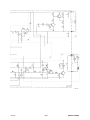
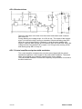
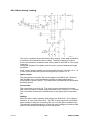
AP1:3,4,5 Start / Stop, Thermal overload, Spot welding
clka1e08
Start / Stop circuit
When the torch trigger switch SB1 is not activated, the voltage between M3
and M4 is 24 V. Pressing the trigger switch shorts the circuit, producing a
voltage of 0 V between M3 and M4.
Thermal overload circuit
The machine contains two thermal overload cutouts, wired in series and
connected to inputs T8 and T9. If either of them operates, the torch trigger
switch circuit cannot be short--circuited, with the result that wire feed cannot be
started. When either of the thermal cutouts has operated, LED V7 is energised
to indicate this via diode D7.
Spot welding circuit
Potentiometer R50 controls the spot welding time and incorporates a switch.
When in the zero position, the switch is open.
When the switch in R50 and torch trigger switch SB1 are closed, capacitor C22
charges up through resistors R32 and R50. Wire feed stops when the voltage
on C22 reaches 8.8 V. The trigger switch must be released and then pressed
again before a new spot weld can be made.
The spot welding time can be adjusted between 0.2 and 2.5 seconds ᐔ30%.

Edition 071024
-- 17 --1sM1725
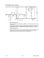
AP1:6 Burnback time
clka1e09
The burn--back time is the time from when wire feed ceases until contactor
KM1 drops off.
During welding, the voltage at pin 13 of IC2 is low. The output of the inverter
at pin 14 is therefore high, turning on transistor Q2 and activating relay RE1.
When the torch trigger switch is released, or when the spot welding time
expires, capacitor C23 charges up via resistors R36, R37 and R38. When the
voltage across C23 reaches 8.8 V, output 14 of IC2 goes low, turning off Q2
and causing relay RE1 to drop off.
AP1:7 Control amplifier and pulse width modulator
The control amplifier compares the set value speed signal with the actual
speed and supplies a control signal to the pulse width modulator. The actual
value speed signal is provided by measuring the motor voltage.
The pulse width modulator controls the frequency and pulse time of current to
the wire feed motor.

Edition 071024
-- 18 --
1sM1725
AP1:8,9 Motor driving / braking
clka1e10
Motor driving circuit
The output stage of the pulse width modulator is connected to transistor Q1 via
resistor R16.
A motor current signal is provided by measuring the voltage across resistor R4,
connected to transistor Q1. If the voltage across R4 exceeds 1.1 V ᐔ60 mV,
the gate pulses to Q1 are inhibited. This provides a current limit of about 11 A.
Motor braking circuit
When wire feed is to stop, the pulse width modulator turns off the pulses to Q1.
Transistors Q3 and Q4 turn on: transistor Q4 provides a path for dynamic
braking current to flow through resistor R47 and diode D17.

Edition 071024
-- 19 --1sM1725
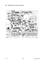
AP1 -- Migmaster 173 / 203 component positions
clka1e05

Edition 071024
-- 20 --
1sM1725
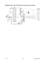
WIRING DIAGRAM, Migmaster 253
Component description
WARNING !
STATIC ELECTRICITY can damage circuit
boards and electronic components.
S
SS
S Observe precautions for handling electrostatic
sensitive devices.
S
SS
S Use proper static--proof bags and boxes.
ESD
AP1 Circuit board
AP2 Digital instrument, accessory
C1, C2, CVS Capacitor 0,1uF/250V
EV1 Fan
KM1 Contactor 42V, 50--60Hz
L1 Inductor
L2, L3 Ferrite core
LF1 Lamp, white, On/Off
M1 Feed unit motor
QF1 Switch, ON/OFF
QF2 Switch, 12--step welding voltage selector
RO Resistor 15Ω/20W
RVS Resistor
RP1 Potentiometer, wire feed speed
RP2 Potentiometer with switch, spot welding
RI Shunt, accessory
RL Resistor
ST1 Thermal oveload cutout, operates at 130
o
C. The cutout is mounted at
the cooling fins of the diode bridge.
TC1 Control transformer
TC2 Transformer for CO2 heater, accessory
TC3 Transformer for digital instrument, accessory
TM1 Main transformer
V1 Diode bridge
VH LED yellow indication, thermal overload
Page is loading ...
Page is loading ...
Page is loading ...
Page is loading ...
Page is loading ...
Page is loading ...
Page is loading ...
Page is loading ...
Page is loading ...
Page is loading ...
Page is loading ...
Page is loading ...
Page is loading ...
Page is loading ...
Page is loading ...
Page is loading ...
Page is loading ...
Page is loading ...
Page is loading ...
Page is loading ...
Page is loading ...
Page is loading ...
Page is loading ...
Page is loading ...
-
 1
1
-
 2
2
-
 3
3
-
 4
4
-
 5
5
-
 6
6
-
 7
7
-
 8
8
-
 9
9
-
 10
10
-
 11
11
-
 12
12
-
 13
13
-
 14
14
-
 15
15
-
 16
16
-
 17
17
-
 18
18
-
 19
19
-
 20
20
-
 21
21
-
 22
22
-
 23
23
-
 24
24
-
 25
25
-
 26
26
-
 27
27
-
 28
28
-
 29
29
-
 30
30
-
 31
31
-
 32
32
-
 33
33
-
 34
34
-
 35
35
-
 36
36
-
 37
37
-
 38
38
-
 39
39
-
 40
40
-
 41
41
-
 42
42
-
 43
43
-
 44
44


ESAB Migmaster 253 User manual
- Category
- Welding System
- Type
- User manual
- This manual is also suitable for
Ask a question and I''ll find the answer in the document
Finding information in a document is now easier with AI
Related papers
-
ESAB How to Switch a Migmaster 203/253 from 230 to 208 vac Troubleshooting instruction
-
-
-
-
-
-
-
-
-
Other documents
-
Simplicity 071024-0 Product information
-
AVT 1605 Two State Servo Controller Operating instructions
-
MIMAKI LA-W Operating instructions
-
Sunpentown SF614P User manual
-
-
-
SPT Evaporative Air Cooler User manual
-
Lincoln Electric Prince XL User manual
-
RKC INSTRUMENT SB1 Installation guide
-
ETS 930D & 930D-FTS User manual