Page is loading ...

©2017 Edelbrock, LLC
Brochure #63-15402
Part #15402
Rev. 12/6/17- NP
EDELBROCK COMPETITION FORD MASS AIR FLOW SENSOR
For use with in Universal Applications
Part #15402
INSTALLATION INSTRUCTIONS
Please study these instructions carefully before installing your new Mass Air Flow (MAF) Sensor. If you have any questions, do not
hesitate to contact our Technical Hotline at: (800) 416-8628 from 7:00 am to 5:00 pm, Monday through Friday, Pacific Standard
Time.
DESCRIPTION: The Edelbrock E-Force Competition MAF sensor is intended only for use in custom air intake systems. This kit
contains the mass air housing and mass air flow sensor only. Construction and design of the rest of the intake system is the
responsibility of the installer. The provided MAF sensor is a blade-style sensor compatible with 2004-2010 F-150’s, and 2005-2010
Mustangs that use a Voltage sensor.
CALIBRATION: This system requires recalibrating the vehicle for the new MAF sensor. Contact a local installer or performance shop
before installing this kit. Do not drive your vehicle with this kit until you correct the vehicle calibration or severe engine
damage will result.
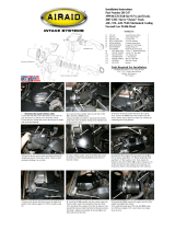
INSTALLATION:
1. Install the supplied MAF sensor in the new MAF sensor housing using the two supplied #8-32 thread-forming screws.
2. Your MAF sensor housing is now ready for installation into your custom air intake system.
3. The MAF sensor housing has 3 threaded inserts (M6x1.0) for installation into your custom shroud. These bolts are evenly
spaced on a 5-1/4” bolt pattern. The MAF housing is a direct bolt in for Airaid shrouds that utilize a 6” filter adapter.
4. Once the installation is complete, attach your engine harness connecter to the MAF sensor.
WARNINGS:
1. Do not attempt to start vehicle before updating PCM or severe engine damage may result.
2. Do not modify the MAFS housing in any way. This could cause inconsistent readings from the MAFS.
3. All PCV hoses, breather hoses, etc., should be plumbed into the air intake downstream of the mass air housing.
4. All air entering the engine must enter through the mass air housing. Any air that bypasses the mass air housing would be
considered a vacuum leak, and thus cannot be compensated for properly by the engine ECU. This includes valve cover
breathers vented to atmosphere.
IMPORTANT NOTE: The transfer function values provided in the table, on the next page, are only provided as a guide. It is always
required that you verify the Air/Fuel ratio with a wideband lambda sensor, installed in front of the catalytic converter, while running
the vehicle on a chassis dyno through the entire RPM & load range.

©2017 Edelbrock, LLC
Brochure #63-15402
Part #15402
Rev. 12/6/17- NP
Edelbrock LLC • 2700 California St. • Torrance, CA 90503
Tech Line: 800-416-8628
Voltage Lb / Min
5 113.449
4.731 97.2757
4.484 83.8695
4.17 68.6985
3.876 56.9055
3.522 44.1957
3.316 37.5833
3.084 31.2542
2.804 24.2298
2.551 18.8963
2.353 15.1953
2.26 13.9668
2.157 12.7689
2.114 12.1323
2.004 10.991
1.758 7.9886
1.604 6.4527
1.517 5.6631
1.422 4.8684
1.32 4.0964
1.204 3.2865
1.142 2.9055
1.007 2.1951
0.931 1.8645
0.838 1.5249
0.735 1.2295
0.603 0.97
0.54 0.8916
0.426 0.8223
0.011 0
Transfer Function
Table
/