Page is loading ...

- Data Brochure
Snow Detector & Melting Control 667
D 667
09/02
1 of 28 © 2002 D 667 - 09/02
3
Red
4
Blk
5
Blu
6
Yel
7
Brn/
SlabMix Ret Sup
8
Boil
9
Com
10
tN2
11
Mix
12
Mix
13
Com
14
Out
15
Melt/Idle
Demand Pmp 2
16 17
System Boiler
18 21
Melting
22 23 25
Sys
P1
24
Power
L
N
Test
Snow Detector & Melting Control 667
Variable Speed Injection
Idle Demand
Signal wiring must be rated at least 300 V
Melt Demand
not testing
testing
testing paused
For maximum heat,
press and hold Test
button for 3 seconds.
Made in Canada by
tekmar Control Systems Ltd.
tektra 900-04
Power 115 V
± 10%
50/60 Hz 600 VA
Relays 230 V (ac) 5 A 1/3 hp, pilot duty 240 VA
Var. Pump 230 V (ac) 2.4 A 1/6 hp, fuse T2.5 A 250 V
Demand 20 to 260 V (ac) 2 VA
off
red
red
Do not apply power
19 20
Input
Outdoor
Sensor
Included
Input
Melt/Idle
Demand
Output
System
Pump
Output
System
Pump
Output
Variable Speed
Injection Pump
Input
115 V (ac)
Power
Supply
Input
Remote Display Module (RDM)
or
Remote Start / Stop Module
OR
158033
Melt Demand
Idle Demand
WWSD
Minimum
Maximum
Water
Melting
Input
Snow/Ice Sensor
090 installed with
Sensor Socket
091 Optional
Input
Slab Sensor
Optional
or
Start
Menu Item
Stop
Do not apply power
Output
Melt Relay
Output
Boiler
1
Var
2
Pwr
H2029A
Input
Universal
Sensor
Included
Input
Universal
Sensor
Included
Input
Universal
Sensor
Included
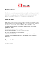
The Snow Detector & Melting Control 667 is a microprocessor-based control which operates a snow melting system. The control
can operate automatically when a Snow/Ice Sensor 090 is installed or the user can manually enable and/or disable the system. The
667 controls a variable speed injection pump to provide both boiler and slab protection. When the control is not in the melting mode,
the system can either be shut down or it can be maintained at an idle temperature for faster response and improved safety. The 667
control includes a large Liquid Crystal Display (LCD) in order to view system status and operating information.
Additional features include:
• Slab protection for the snow melting system
• Boiler protection
• Manual Override
• Warm Weather Shut Down (WWSD)
• Cold Weather Cut Out (CWCO)
• Remote display and adjustment capabilities.
• Test sequence to ensure proper component operation.
• Pump exercising.
• Viscosity compensation.
• CSA C US Certified (approved to applicable UL standards)

© 2002 D 667 - 09/02 2 of 28
This brochure is organized into four main sections. They are: 1) Sequence of Operation, 2) Installation, 3) Control Settings, and
4) Troubleshooting. The Sequence of Operation section has 6 sub-sections. We recommend reading Section A: General of the
Sequence of Operation, as this contains important information on the overall operation of the control. Then read to the sub-sections
that apply to your installation.
The Control Settings section (starting at DIP Switch Settings) of this brochure describes the various items that are adjusted and
displayed by the control. The control functions of each adjustable item are described in the Sequence of Operation.
User Interface..................................................Pg 2
Description of Display Elements ..................Pg 3
Sequence of Operation..................................Pg 4
Section A: General Operation ..............Pg 4
Section B: Snow Melting ......................Pg 5
Section C: Boiler Operation .................Pg 7
Section D: Melting Enable / Disable ....Pg 8
Section E: Melting Operation ...............Pg 11
Section F: Idling Operation ..................Pg 12
Installation.......................................................Pg 12
Electrical Connections..........................Pg 13
Testing The Wiring.................................Pg 15
How To Use The Data Brochure
Table Of Contents
DIP Switch Settings........................................Pg 16
Access Levels .................................................Pg 17
Control Settings..............................................Pg 17
View Menu ..............................................Pg 17
Adjust Menu ...........................................Pg 18
Monitor Menu .........................................Pg 20
Schedule Menu ......................................Pg 21
Miscellaneous Menu .............................Pg 22
Testing and Troubleshooting ........................Pg 23
Error Messages .....................................Pg 24
Technical Data ................................................Pg 28
Limited Warranty ............................................Pg 28
User Interface
The 667 uses a Liquid Crystal Display (LCD) as the method of supplying information. You use the LCD in order to setup and monitor
the operation of your system. The 667 has four push buttons (Menu, Item, ▲ (Start), ▼ (Stop)) for selecting and adjusting settings.
As you program your control, record your settings in the Adjust Menu table which is found in the second half of this brochure.
Reference Material: Essay E 021: Mixing Methods and Sizing of Variable Speed Injection Pumps
Menu
All of the items displayed by the control are organized into various menus. These menus
are listed on the left hand side of the display (Menu Field). To select a menu, use the
Menu button. By pressing and releasing the Menu button, the display will advance to
the next available menu. Once a menu is selected, there will be a group of items that can
be viewed within the menu.
Item
The abbreviated name of the selected item will be displayed in the item field of the dis-
play. To view the next available item, press and release the Item button. Once you have
reached the last available item in a menu, pressing and releasing the Item button will
return the display to the first item in the selected menu.
Adjust
To make an adjustment to a setting in the control, begin by selecting the appropriate
menu using the Menu button. Then select the desired item using the Item button.
Finally, use the ▲ and / or ▼ button to make the adjustment.
Additional information can be gained by observing the Status field of the LCD. The status
field will indicate which of the control’s outputs are currently active. Most symbols in the
status field are only visible when the View Menu is selected.
Menu Item
Start Stop
Menu
Start Stop
Item
Menu Item
Start Stop

3 of 28 © 2002 D 667 - 09/02
Symbol Description
Display
M
e
l
t
D
e
m
a
n
d
I
d
l
e
D
e
m
a
n
d
WW
SD
Minim
um
Ma
x
i
m
um
W
ater
Meltin
g
Buttons
Selects Menus, Items and
adjusts settings
Number Field
Displays the current value
of the selected item
Menu Field
Displays the
current menu
Item Field
Displays an abbreviated
name of the selected item
Status Field
Displays the current
status of the control's
inputs, outputs and
operation
2
Defi nitions
The following defined terms and symbols are used throughout this manual to bring attention to the presence of hazards of various risk
levels, or to important information concerning the life of the product.
INSTALLATION
CATEGORY II
- Warning Symbol: Indicates presence of hazards which can cause severe personal injury, death or
substantial property damage if ignored.
- Double insulated
- Local level, appliances
Lock / Unlock
Displays whether the access levels are
locked or unlocked.
°F, °C, sec, min, hr
Units of measurement.
°
F,
°
C, sec,
min, hr
Ovr
Override
Displays when the control is in override
mode.
Pump
Displays when the system pumps are
operating.
Pointer
Displays the control operation as indicated
by the text.
Mixing Device Output Scale
Shows output of injection pump. Arrows show
whether the output is increasing or decreasing.
Burner
Displays when the Boiler relay is turned on.
Warning
Displays when an error exists or when a limit
has been reached.

© 2002 D 667 - 09/02 4 of 28
Sequence of Operation
Section A
General
Operation
Page 4
Section B
Snow
Melting
Page 5 - 6
Section C
Boiler
Operation
Page 7 - 8
Section D
Melting Enable/
Disable
Page 8 - 10
Section E
Melting
Operation
Page 11
Section F
Idling
Operation
Page 12
POWERING UP THE CONTROL
When the Snow Detector & Melting Control 667 is powered up, the control displays all LCD segments for 2 seconds, then the con-
trol type number in the LCD for 2 seconds. Next, the software version is displayed for 2 seconds. Finally, the control enters into the
normal operating mode and the LCD defaults to displaying the current outdoor air temperature.
MIXING DEVICE
Variable Speed Injection Pump
A standard wet rotor circulator is connected to the 667 on the Var
and Pwr Mix terminals (1 and 2). The 667 increases or decreases the
power output to the circulator based on the system requirements. For
correct sizing and piping of the variable speed injection pump, refer to
Essay E 021. A visual indication of the current variable speed output is
displayed in the LCD in the form of a segmented bar graph.
Section A: General Operation
Mixing
Sensor
Boiler Supply
Sensor
OR
Boiler Return
Sensor
MIXING MAXIMUM (MIX MAX)
The MIX MAX sets the highest fluid temperature that the control is allowed to calculate as the mixing target temperature. If the
control does target the MIX MAX setting, and the MIX SUP temperature is near the MIX MAX, the Maximum pointer is displayed in
the LCD while the MIX SUP temperature is being viewed.
BOILER PROTECTION (Boil MIN)
The 667 is capable of providing boiler protection from cold mixing system
return fluid temperatures. If the boiler sensor temperature is cooler than
the Boil MIN setting while the boiler is firing, the 667 reduces the output
from the mixing device. This limits the amount of cool return water to the
boiler and allows the boiler temperature to recover. This feature can only
be used if the Boil SENS item is set to SUP or RET. The 667 can not
provide boiler protection if the Boil SENS item is set to NONE.
EXERCISING (EXERCISE)
The 667 has a built-in pump and valve exercising function. The exercising period is adjustable and is factory set at 70 hours. If a
pump output has not been operated at least once during every exercising period, the control turns on the output for 10 seconds.
This minimizes the possibility of a pump seizing during a long period of inactivity.
Note: The exercising function does not work if power to the control or pumps is disconnected.

5 of 28 © 2002 D 667 - 09/02
Section B: Snow Melting
SLAB PROTECTION (∆T MAX)
The control can limit the rate at which heat is applied to the zone through the ∆T MAX
setting. The ∆T (delta T) is the temperature difference between the snow melting supply
temperature and the snow melting return temperature. By limiting this temperature dif-
ference, the rate at which heat is applied to the zone can be controlled and thermal
stresses in the slab can be minimized. When the control is operating at the ∆T MAX, the
Maximum pointer can be seen when viewing the ∆T item in the View menu. The control
provides slab protection differently based on boiler sensor placement.
Section B1
General
Snow Melting
Section B1: General Snow Melting
VISCOSITY COMPENSATION (EXCEEDING ∆T MAX)
At low temperatures, the glycol solutions used in snow melting systems become very viscous and difficult to pump. In order to
overcome this condition during a cold start of a snow melting system, the 667 is allowed to exceed the ∆T MAX setting for a period
of time in order to warm the glycol solution. This allows the control to compensate for the high viscosity of the glycol solution and is
used when the mixing return temperature is below 30°F (-1°C). When the control exceeds the ∆T MAX setting, the Maximum pointer
will flash when viewing the ∆T item in the View menu.
SOFT START
When the control starts applying heat to the slab, the supply temperature to the snow melting system is ramped up over a period of
time until it reaches the target mixed supply temperature. This feature helps reduce thermal stresses in the slab.
Note: This operation only occurs if the Boil SENS item is set to RET or NONE.
RUNNING TIME (RUN TIME)
The running time is the length of time that the system operates once it has reached its slab target temperature. During the time that
the system is approaching its slab target temperature, the RUN TIME does not decrease. Once the system reaches its slab target
temperature, the RUN TIME begins counting down. When the RUN TIME reaches 0:00 as displayed in the STATUS item in the View
menu, the system has finished melting.
Note: The running time is only applicable when a manual melting enable signal starts the snow melting system. Refer to
Section D1 for a description of a manual melting enable.
WARM WEATHER SHUT DOWN (WWSD)
There is a warm weather shut down for the system. When both the slab temperature of the system and the outdoor tempera-
ture exceed the system’s melting temperature by more than 2°F (1°C), the system enters into WWSD. In WWSD, the system is
shut down in order to conserve energy. While the system is in WWSD, the word WWSD is displayed in the STATUS item in the
View menu. The 667 turns on the WWSD pointer in the display.
COLD WEATHER CUT OFF (CWCO)
Maintaining the system at either the melting or idling temperature during extremely cold temperatures can be expensive or impossi-
ble. The control turns the snow melting system off when the outdoor air temperature drops below the Cold Weather Cut Off (CWCO)
temperature. While the control is in CWCO, the word CWCO is displayed in the STATUS item in the View menu. The heater in the
sensor is kept on during CWCO until the control detects moisture. If water is detected, the heater is turned off but the control retains
the moisture detected information. When the outdoor temperature rises above the CWCO temperature, the control exits CWCO and
if the Snow / Ice Sensor 090 detected moisture during CWCO, the control initiates melting mode. If the control has been started prior
to the CWCO, it resumes the melting mode once the outdoor air temperature rises above the CWCO temperature.
tensile stresses

© 2002 D 667 - 09/02 6 of 28
STATUS (STATUS)
While in the View menu there are a number of items available to determine the current status of the system. To view the current
status of the system, select the STATUS item in the View menu.
• STRT The word STRT is displayed after the snow melting system has been manually enabled. It is displayed until the
system reaches its slab target temperature. If the system is at its slab target temperature, STRT is displayed for
five seconds after the snow melting system has started operation. This is to verify that the control has entered
into the melting mode.
• STOP The word STOP is displayed for five seconds after the snow melting system has been manually disabled. The
word STOP is also displayed if either a Remote Start / Stop Module 039, Remote Display Module 040 or the
Stop button on the control stops the snow melting system and an external melt demand is still present.
• IDLE The word IDLE is displayed as long as the system is operating at its idling temperature.
• EXT The word EXT is displayed when the RUN TIME has reached 0:00 and the control still has an external melt
demand. In this situation, the system continues melting until the melt demand is removed or the control
is stopped.
• DET The word DET is displayed after the snow melting system has been automatically enabled by the Snow / Ice
sensor 090 and the system is at its slab target temperature. DET is also displayed once the control is manually
enabled after automatic detection by the 090 and the running time has counted down to 0:00.
• 0:00 to 23:59 hr While the system is up to temperature and melting, the remaining RUN TIME is displayed.
• INF If an infinite RUN TIME is selected and the system is melting, INF is displayed.
• WWSD When the system is in Warm Weather Shut Down, WWSD is displayed.
• CWCO When the control is in Cold Weather Cut Off, CWCO is displayed.
SNOW MELTING OVERRIDE
If the AWAY setting is selected in the Schedule menu, the snow melting system is shut
down. Both the Melting and Idling temperatures are ignored as long as the control remains
in the AWAY mode.
SYSTEM PUMP OPERATION (Sys P1 and System Pmp 2)
The system pump contacts close and remain closed as long as the system is either in the Melting or Idling mode. The system pump
contacts shut off if the control is in CWCO, WWSD, or if there is no call for Melting or Idling.
MELTING CONTACT OPERATION
The Melting contact (terminals 21 and 22) closes and remains closed as long as the system is in melting mode. This contact can
be used as an external signal to indicate that the system is currently in melting mode. This contact can also be used as a means of
prioritizing or enabling multiple snow melting controls.
PURGE
The system pumps continue to operate for up to 2 minutes after the last demand is removed. This purges the residual heat from the
boiler into the snow melting slab. If the boiler temperature drops below the Boil MIN setting after 20 seconds, the purge is aborted
and the system pumps are turned off.

7 of 28 © 2002 D 667 - 09/02
BOILER SENSOR ON THE SUPPLY (Boil SENS = SUP)
When operating a boiler that is dedicated to a snow melting system, the 667 is designed
to operate the boiler as efficiently as possible. The boiler is cycled based on the mixing
supply fluid temperature. This is to provide longer and more efficient boiler cycles. This
mode of operation only works if the Boil SENS item is set to SUP.
Section C: Boiler Operation
Section C1
Boiler Supply
Sensor
Section C3
No Boiler
Sensor
Section C2
Boiler Return
Sensor
Section C1: Boiler Supply Sensor
BOILER MINIMUM (Boil MIN)
The Boil MIN is the lowest water temperature that the control is allowed to use as a boiler target temperature. If the boiler is oper-
ating, and the boiler supply temperature is near the Boil MIN setting, the Minimum pointer turns on in the LCD while the Boil SUP
temperature is being viewed. If the installed boiler is designed for condensing or low temperature operation, set the Boil MIN adjust-
ment to OFF.
FIRE DELAY (FIRE DLY)
The FIRE DLY is the delay time that may occur between the time that
the 667 closes the Boiler contact and when the burner fires. This delay
is usually the result of burner pre-purge or other forms of time delay
built into the burner’s safety circuits.
Boiler Temperature
Minimum
On Time
Minimum
On Time
Minimum
Off Time
Boiler Contact Closes
Boiler Fires
Fire
Delay
Fire
Delay
Time
BOILER MASS (Boil MASS)
The Boil MASS setting allows the 667 to adjust to different types of heat sources depending on their thermal mass.
Light (LITE)
The LITE setting is selected if the boiler that is used has a low thermal mass. This means that the boiler has a very small water
content and has very little metal in the heat exchanger. A boiler that has a low thermal mass comes up to temperature quite rap-
idly when fired. This is typical of many copper fin-tube boilers.
Medium (MED)
The MED setting is selected if the boiler that is used has a medium thermal mass. This means that the boiler either has a large
water content and a low metal content or a low water content and a high metal content. This is typical of many modern residential
cast iron boilers or steel tube boilers.
Heavy (HEVY)
The HEVY setting is selected if the boiler that is used has a high thermal mass. This means that the boiler has both a large water
content and a large metal content. A boiler that has a high thermal mass is relatively slow in coming up to temperature. This is
typical of many commercial cast iron and steel tube boilers.
DIFFERENTIAL (DIFF)
An on / off heat source such as a boiler must be operated with a differential in order to prevent short cycling. With the 667, either a
fixed or an automatic differential may be selected.
Fixed Differential
The differential is centered around the target temperature. If the temperature drops 1/2 the differential below the target
temperature, the 667 closes the boiler contact to fire the boiler. If the temperature rises 1/2 of the differential above the target
temperature, the 667 opens the boiler contact to turn off the boiler.

© 2002 D 667 - 09/02 8 of 28
Section D1
Snow Melting
Enable
Section D2
Snow Melting
Disable
The snow melting system can be enabled manually or automatically. A melting enable signal applied to the control places the system
into the melting mode. If a melting enable signal is applied once the system is already in the melting mode, the control responds to
the last command received.
MANUAL MELTING ENABLE
A manual melting enable signal requires the user to manually start the snow melting system and can be provided from the Start
button on the control, Remote Start / Stop Module 039, Remote Display Module 040, or an external melt demand.
Auto Differential (AUTO)
If the AUTO differential is selected, the 667 automatically adjusts
the differential setting under the current load conditions to avoid
short cycling.
Section C2: Boiler Return Sensor
Section C3: No Boiler Sensor
BOILER SENSOR ON THE RETURN (Boil SENS = RET)
The boiler sensor should be located on the boiler return if the 667 is one of many controls
that can call for boiler operation. When in the return mode, the 667 provides a boiler enable
through the Boiler contact. The 667 no longer tries to control the boiler supply water tem-
perature directly, but allows the boiler to operate at its operating aquastat setting when
required. If this mode of operation is selected, the boiler pump should either operate contin-
uously, or be operated in parallel with the system pump contact (Sys P1). When the mixing
device begins to ramp up, the Boiler contact closes on the 667. The Boiler contact remains
closed until the mixing device no longer requires heat. With the sensor on the boiler return,
the 667 is still capable of providing boiler protection as described in section A.
Snowmelt Load
Time
Differential
On
Off
NO BOILER SENSOR (Boil SENS = NONE)
The 667 is capable of operating without a boiler sensor if desired. Without a boiler sensor,
the 667 is unable to provide boiler protection. In this mode of operation, the Boiler contact
is used to provide a boiler enable. When the mixing device begins to ramp up, the Boiler
contact on the 667 closes. The Boiler contact remains closed until the mixing device no
longer requires heat. This type of application is typical if the 667 is drawing heat from a
source that already incorporates some form of boiler protection.
Section D: Melting Enable / Disable
Section D1: Snow Melting Enable

9 of 28 © 2002 D 667 - 09/02
Start Button on the Control
The snow melting system is enabled by pressing the Start button on the control while
in the View menu. The control then displays the RUN TIME setting to allow the user
to adjust it. Once the snow melting system is enabled, the word STRT is displayed for
at least 5 seconds in the STATUS item while in the View menu. If the Start button on
the control is pressed while the system is already melting and up to temperature, the
running time counter is reset to the RUN TIME setting.
Remote Start / Stop Module 039
The snow melting system is enabled by pressing the button on the front of the 039.
While the zone is coming up to temperature, a green indicator light flashes on the front
of the 039. Once the zone is up to temperature and the RUN TIME is counting down,
the green indicator light on the front of the 039 is on solid.
Remote Display Module 040
The snow melting system is enabled by pressing the ▲ button on the 040 while in
the View menu. The 040 then displays the RUN TIME setting to allow the user to
adjust it. Once the snow melting system is enabled, the word STRT is displayed for at
least 5 seconds in the STATUS item while in the View menu.
External Melt Demand (DIP switch set to Melt Demand)
The snow melting system is enabled when a voltage between 24 and 240 V (ac) is
applied across the Melt/Idle Demand terminals (15 and 16). An external melt demand
must be present for at least 4 seconds in order to start the snow melting system. If
the RUN TIME reaches 0:00 and the external melt demand is still present, the control
continues melting until the external melt demand is removed or the system is other-
wise stopped.
Note: This operation only occurs if the Idle Demand / Melt Demand DIP switch is set
to the Melt Demand position.
Menu Item
Start Stop
7
9
8
Start / Stop
StopStart
Idle Demand
Melt Demand
Idle Demand
Melt Demand
15
Melt / Idle
Demand
16
24 to 240 V (ac)
AUTOMATIC MELTING ENABLE (Snow / Ice Sensor 090)
The 667 can use the Snow / Ice Sensor 090 to provide an automatic melting enable signal to start the snow
melting system. The control continually monitors the 090 for the presence of moisture. Once moisture is
detected, the Water pointer is displayed in the LCD and the snow melting system is enabled.
Water Detection Sensitivity (SENSTVTY)
The 667 has a sensitivity setting which compensates for varying outdoor conditions which could affect
how the moisture detector in the 090 interprets the presence of moisture. This adjustable setting is
available through the SENSTVTY item in the Adjust menu of the control. As snow becomes contami-
nated with dirt, and as the sensor itself becomes dirty, the control may incorrectly indicate the presence
of water. If this condition occurs, clean the surface of the sensor and / or turn down the SENSTVTY
setting. If the snow in your area is very clean, the SENSTVTY setting may need to be increased before
snow is detected. If AUTO is selected, the control automatically adjusts the sensitivity level used to
detect moisture.

© 2002 D 667 - 09/02 10 of 28
The snow melting system can be disabled manually or automatically. A melting disable signal applied to the control takes the zone
out of the melting mode. Once the snow melting system is disabled, the zone operates in the idling mode. The idling mode allows the
zone to be operated either at a lower temperature or turned off.
MANUAL MELTING DISABLE
A manual melting disable signal requires the user to manually stop the snow melting system and can be provided from the Stop
button on the control, Remote Start / Stop Module 039, Remote Display Module 040, or an external idle demand.
Stop Button on the Control
The Stop button on the control can be used to stop the snow melting system. The snow melting system is disabled by pressing
the Stop button on the control while in the View menu. Once the snow melting system is disabled, the word STOP is displayed
for 5 seconds in the STATUS item while in the View menu.
Remote Start / Stop Module 039
A Remote Start / Stop Module 039 can be used to stop the snow melting. The snow melting system is disabled by pressing the
button on the face of the 039. When the system is stopped, a solid red indicator light is displayed on the face of the 039 for five
seconds. If the snow melting system is disabled while there is still an external melt demand for snow melting, the 039 displays a
solid red indicator light until the external demand is removed.
Remote Display Module 040
A Remote Display Module 040 can be used to stop the snow melting system. The snow melting system is disabled by pressing
the ▼ button on the 040 while in the View menu. Once the snow melting system is disabled, the word STOP is displayed for 5
seconds in the STATUS item while in the View menu.
Section D2: Snow Melting Disable
External Idle Demand (DIP switch set to Idle Demand)
The snow melting system is disabled when a voltage between 24 and 240 V (ac) is
applied across the Melt/Idle Demand terminals (15 and 16). An external idle demand
must be present for at least 4 seconds in order to stop the snow melting system.
Note: This operation only occurs if the Idle Demand / Melt Demand DIP switch is set to
the Idle Demand position.
If the snow melting system is placed into idling mode by an external idle demand, then
a manual melting enable signal is applied, the idle demand is overridden until either the
running time has expired, a stop signal is given, or the external idle demand is removed
and reapplied.
AUTOMATIC MELTING DISABLE (Snow / Ice Sensor 090)
Once the 090 is dry, the Water pointer turns off in the LCD. The system slab temperature has to be at least the slab target tem-
perature for a minimum of thirty minutes in order for the system to turn off. If a manual melting disable signal is applied the snow
melting system turns off immediately.
15
Melt / Idle
Demand
16
24 to 240 V (ac)
Idle Demand
Melt Demand
Idle Demand
Melt Demand

11 of 28 © 2002 D 667 - 09/02
Section E: Melting Operation
Section E1
General Melting
Operation
Section E1: General Melting Operation
In order for the snow melting system to be started, one of the methods described in section D1 must be used. Once a melting enable
signal is applied and the system is not in WWSD or CWCO, the melting mode begins. When the control is in the melting mode, the
Melting pointer is visible in the View menu. The MELT setting in the Adjust menu sets the slab surface temperature. When the system
is melting and the slab temperature is warming up to the slab target temperature, STRT is displayed in the STATUS item while in the
View menu. The system finishes melting when the slab temperature has been at least the slab target temperature for a period of time.
This period of time is based on whether an automatic or manual melting enable signal starts the snow melting system.
If an automatic melting enable signal starts the snow melting system and the slab temperature reaches the slab target temperature,
DET is displayed in the STATUS item while in the View menu. The system continues to melt until the 090 becomes dry and any addi-
tional running time has expired. Once the melting mode is complete, the system operates in the idling mode.
If a manual melting enable signal starts the snow melting system, the running time is displayed in the STATUS item while in the View
menu and begins counting down once the slab temperature reaches the slab target temperature. The system continues to melt until
the running time counts down to 0:00 and there is no external melt demand. Once the melting mode is complete, the system operates
in the idling mode.
SLAB TEMPERATURE CONTROL
The 667 uses a snow / ice sensor or slab sensor to provide slab tem-
perature control.
Slab Sensor
If a Slab Sensor is used, the control assumes that the sensor is
approximately 1 inch below the surface of the snow melting slab.
Since this point is closer to the source of the heat, this point is
warmer than the surface of the slab. Therefore, the sensor must
be maintained at a higher temperature in order to ensure that the
surface of the slab is maintained at the correct temperature. The
amount of temperature difference between the surface of the
slab and the slab sensor changes with the outdoor temperature.
Therefore, the slab core temperature is increased as the outdoor
air temperature drops. The temperature displayed as SLAB is the
temperature of the slab sensor.
Snow / Ice Sensor 090
The slab temperature is displayed as SLAB in the view menu. This temperature is calculated from the edge and center sensors
built into the 090.
SLAB TARGET TEMPERATURE (SLB TRG)
The SLAB TRG temperature is determined from the melting setting, idle setting and the outdoor air temperature. The control dis-
plays the temperature that it is currently trying to maintain at the slab sensor. If the control does not presently have a requirement
for heat, it displays “---“ in the STATUS item while in the View menu.
ADDITIONAL MELTING TIME (ADD MELT)
In cases where areas of the snow melting system haven’t completely
melted after the melting mode has finished and the 090 is dry, the 667
has a function in which additional time can be added to melt the zone.
This is an adjustable time through the ADD MELT item in the Adjust
menu of the control. The ADD MELT time is calculated into a running
time and is displayed in the STATUS item while in the View menu.
Once the 090 becomes dry and the slab temperature is at least the
slab target temperature, the running time starts counting down.
Surface temperature = 35˚F
Decreasing Air Temperature
Increasing Slab Core Temperature
Slab Surface Temperature is Constant
Slab Outdoor
Reset
Slab Outdoor
Reset
Core (sensor)
is warmer
Dry
Snow
Ice Sensor

© 2002 D 667 - 09/02 12 of 28
Section F1
General Idling
Operation
Section F: Idling Operation
When the snow melting system starts from a cold temperature, the time required for the system to reach the melting temperature may
be excessive. To decrease this start up time, the 667 has an idling feature which can maintain the system at a lower temperature.
This feature is also useful for preventing frost and light ice formation. The IDLING setting in the Adjust menu sets the slab surface
temperature while the control is in the idling mode. When in the idling mode, IDLING is displayed in the STATUS item while in the View
menu. If idling is not desirable, the IDLING setting may be set to OFF.
CAUTION
Improper installation and operation of this control could result in damage to the equipment and possibly even personal injury. It
is your responsibility to ensure that this control is safely installed to all applicable codes and standards. This electronic control is
not intended for use as a primary limit control. Other controls that are intended and certified as safety limits must be placed into
the control circuit. Do not open the control. Refer to qualified personnel for servicing. Opening voids warranty and can result in
damage to the equipment and possibly even personal injury.
STEP ONE
–––––––––––
GETTING READY
Check the contents of this package. If any of the contents listed are missing or damaged, please contact your wholesaler or tekmar
sales representative for assistance.
Type 667 includes: One Snow Detector & Melting Control 667, One Outdoor Sensor 070, Three Universal Sensors 071, Data
Brochures D 667, D 070, D 001, User Brochure U 667, Application Brochure A 667, Essay E 021.
Note: Carefully read the details of the Sequence of Operation to ensure that you have chosen the proper control for
your application.
STEP TWO
––––––––––
MOUNTING THE BASE
Remove the control from its base by pressing down on the release clip in the wiring chamber and sliding the control away from it.
The base is then mounted in accordance with the instructions in the Data Brochure D 001.
STEP THREE
–––––––––
ROUGH-IN WIRING
All electrical wiring terminates in the control base wiring chamber. The base has standard 7/8” (22 mm) knockouts which accept
common wiring hardware and conduit fittings. Before removing the knockouts, check the wiring diagram and select those sections
of the chamber with common voltages. Do not allow the wiring to cross between sections as the wires will interfere with safety
dividers which should be installed at a later time.
• Power must not be applied to any of the wires during the rough-in wiring stage.
• All wires are to be stripped to a length of 3/8 in (9mm) to ensure proper connection to the control.
• Install the Outdoor Sensor 070, Boiler Sensor 071 and Mixing Sensor(s) 071 according to the installation instructions in the Data
Brochure D 070 and run the wiring back to the control.
• Install the Snow / Ice Sensor 090 according to the installation instructions in the Data Brochure D 090 and run the wiring back
to the control. See Data Brochure D 090 for very important details on sensor location and installation.
• If a Slab Sensor is used, install the slab sensor according to the installation instructions in the Data Brochure D 079 and run the
wiring back to the control. See page 14 for very important details on sensor location and installation.
• If a Remote Display Module (RDM) 040 is used, install the RDM according to the installation instructions in the Data Brochure
D 040 and run the wiring back to the control.
• If a Remote Start / Stop Module 039 is used, install the module according to the installation instructions in the Data Brochure
D 039 and run the wiring back to the control.
Section F1: General Idling Operation
Installation

13 of 28 © 2002 D 667 - 09/02
• Run wire from other system components (pumps, boiler, etc.) to the control.
• Run wires from the 115 V (ac) power to the control. Use a clean power source with a minimum 15 A circuit to ensure proper
operation. Multi-strand 16 AWG wire is recommended for all 115 V (ac) wiring due to its superior flexibility and ease of installa-
tion into the terminals.
STEP FOUR
––––––––––
ELECTRICAL CONNECTIONS TO THE CONTROL
The installer should test to confirm that no voltage is present at any of the wires. Push the control into the base and slide it down
until it snaps firmly into place.
Powered Input Connections
Power
25
115 V (ac)
L
N
24
115 V (ac) Power
Connect the 115 V (ac) power supply to the Power L and Power N terminals (24
and 25). This connection provides power to the microprocessor and display of the
control. As well, this connection provides power to the Sys P1 terminal (23) from the
Power L terminal (24).
Melt / Idle Demand
To generate a melt demand or idle demand, a voltage between 24 V (ac) and
240 V (ac) must be applied across the Melt/Idle Demand terminals (15 and 16).
Output Connections
Boiler Contacts
The Boiler terminals (19 and 20) are an isolated output in the 667. There is no power
available on these terminals from the control. These terminals are used as a switch
to either make or break the boiler circuit. When the 667 requires the boiler to fire, it
closes the contact between terminals 19 and 20.
System Pump Contact (Sys P1)
The Sys P1 output terminal (23) on the 667 is a powered output. When the relay in
the 667 closes, 115 V (ac) is provided to the Sys P1 terminal (23) from the Power L
terminal (24). To operate the system pump, connect one side of the system pump
circuit to terminal 23 and the second side of the pump circuit to the neutral (N) side
of the 115 V (ac) power supply.
System Pump Contact (System Pmp 2 )
The System Pmp 2 terminals (17 and 18) are an isolated output in the 667. There is
no power available on these terminals from the control.
If the System Pmp 2 contact is used, connect the pump circuit to the System Pmp
2 terminals (17 and 18).
Melting Contact
The Melting terminals (21 and 22) are an isolated output in the 667. There is no
power available on these terminals from the control. These terminals are used as a
switch to make or break an external circuit.
Variable Speed Injection Pump
The 667 can vary the speed of a permanent capacitor, impedance protected or
equivalent pump motor that has a locked rotor current of less than 2.4 A. Most
small wet rotor circulators are suitable as described in Essay E 021. The 667 has an
internal overload fuse which is rated at 2.5 A 250 V (ac). Contact your tekmar sales
representative for details on the repair procedures if the fuse is blown.
15
Melt / Idle
Demand
16
24 to 240 V (ac)
Boiler
20
19
Sys
P1
115 V (ac)
N
L
Power
25
L
N
24
23
17
18
L
N
115 V (ac)
System
Pmp 2
1
Var
2
Pwr
Mix
115 V (ac)
N
L

© 2002 D 667 - 09/02 14 of 28
Outdoor Sensor
Connect the two wires from the Outdoor Sensor 070 to the Com and
Out terminals (13 and 14). The outdoor sensor is used by the 667 to
measure the outdoor air temperature.
Boiler Sensor
Connect the two wires from the Boiler Sensor 071 to the Boil and
Com terminals (8 and 9). The boiler sensor is used by the 667 to
measure the water temperature of the boiler.
Mixing Supply Sensor
Connect the two wires from the Mixing Supply Sensor 071 to the
Mix Sup and Com terminals (12 and 9). The mixing supply sensor is
used by the 667 to measure the fluid supply temperature after the
mixing device. Normally the sensor is attached downstream of the
mixing pump.
Mixing Return Sensor
Connect the two wires from the Mixing Return Sensor 071 to the
Com and Mix Ret terminals (9 and 11). The mixing return sensor is
used by the 667 to measure the fluid return temperature from the
snow melting slab.
EITHER: Snow / Ice Sensor 090
Connect the red wire from the sensor cable to the Red terminal (3),
connect the black wire from the sensor cable to the Blk terminal (4),
connect the blue wire from the sensor cable to the Blu terminal (5),
connect the yellow wire from the sensor cable to the Yel terminal (6)
and connect the brown wire from the sensor cable to the Brn/Slab
terminal (7). The snow / ice sensor is used by the 667 to measure
the slab surface temperature. This sensor must be installed flush
with the slab surface and 1/2 way between the heating pipes. See
Data Brochure D 090 for installation instructions regarding the
Snow / Ice Sensor 090 and Sensor Socket 091.
OR: Slab Sensor
If a Snow / Ice Sensor 090 is not used, a slab sensor can be used.
If a slab sensor is used, connect the two wires from the slab sensor
to the Blk and Brn/Slab terminals (4 and 7). The slab sensor is used
by the 667 to measure the slab temperature.
Note: Proper sensor placement is critical for correct operation
of the 667 control. The slab sensor must be installed 1/2 way
between the heating pipes and 1’’ (25 mm) below the surface of
the slab. Although the sensor can be installed directly into the slab,
we recommend that the sensor be installed in tubing or conduit in
such a manner that the sensor can be removed and replaced in
case of failure.
13
14
Com
Out
Boiler
Sensor
8
9
Boil
Com
10
9
11
12
Com
tN2
Mix
Ret
Mix
Sup
Mix Supply
Sensor
9
Com
10
tN2
11
Mix
Ret
Mix Return
Sensor
3
Red
4
Blk
5
Blu
6
Yel
7
Brn/
Slab
5
4
6
7
Blk
Blu
Yel
Brn/
Slab
If a variable speed injection pump is used, connect one of the wires from the variable speed injection pump to the Var terminal
(1) on the 667. Connect the Pwr Mix terminal (2) to the live (L) side of the 115 V (ac) power source. The other wire on the variable
speed injection pump must be connected to the neutral (N) side of the 115 V (ac) power supply.
Sensor and Unpowered Input Connections
Do not apply power to these terminals as this will damage the control.

15 of 28 © 2002 D 667 - 09/02
tekmar Net™ (tN2) Device
A Remote Display Module (RDM) 040 or Remote Start / Stop Module 039 can
be connected to the tekmar Net™ (tN2) input. Connect the Com terminal from
the appropriate tN2 device to the Com terminal (9) on the 667. Connect the
tN2 terminal from the appropriate tN2 device to the tN2 terminal (10) on the 667.
Note: The wires from the RDM and Remote Start / Stop Module are polarity sensi-
tive. The tN2 device does not operate correctly if the wires are reversed.
9
10
8
9
Boil
Com
STEP FIVE
TESTING THE WIRING
Each terminal block must be unplugged from its header on the control before power is applied for testing. To remove the terminal
block, pull straight down from the control.
The following tests are to be performed using standard testing practices and procedures and should only be carried out by properly
trained and experienced persons.
A good quality electrical test meter, capable of reading from at least 0 – 300 V (ac) and at least 0 – 2,000,000 Ohms, is essential to
properly test the wiring and sensors.
Test The Sensors
In order to test the sensors, the actual temperature at each sensor
location must be measured. A good quality digital thermometer with
a surface temperature probe is recommended for ease of use and
accuracy. Where a digital thermometer is not available, a spare
sensor can be strapped alongside the one to be tested and the
readings compared. Test the sensors according to the instructions
in the Data Brochure D 070, D 079 or D 090.
Test The Power Supply
Make sure exposed wires and bare terminals are not in contact
with other wires or grounded surfaces. Turn on the power and
measure the voltage between the Power L and Power N terminals
(24 and 25) using an AC voltmeter, the reading should be between
103.5 and 126.5 V (ac).
Test The Powered Inputs
Melt / Idle Demand
If a Melt / Idle demand is used, measure the voltage between
the Melt/Idle Demand terminals (15 and 16). When the melting
or idling device calls for heat, you should measure between 20
and 260 V (ac) at the terminals. When the melting or idling device
is off, you should measure less than 5 V (ac).
L
N
25
Power
V
103.5 to 126.5 V (ac)
24
15
16
Melt/Idle
Demand
V
20 to 260 V (ac)
23
24
25
Sys
P1
Power
N
L
115 V (ac)
N
L
Test The Outputs
System Pump (Sys P1)
If a system pump is connected to the Sys P1 terminal (23), make sure that power
to the terminal block is off and install a jumper between the Sys P1 and Power L
terminals (23 and 24). When power is applied to the Power L and Power N terminals
(24 and 25), the system pump should start. If the pump does not turn on, check
the wiring between the terminal block and pump and refer to any installation or
troubleshooting information supplied with the pump. If the pump operates properly,
disconnect the power and remove the jumper.

© 2002 D 667 - 09/02 16 of 28
System Pump (System Pmp 2 )
If a pump is connected to the System Pmp 2 terminals (17 and 18), make sure power to the pump circuit is off and install a
jumper between the System Pmp 2 terminals (17 and 18). When the circuit is powered up, the pump should turn on. If no
response occurs, check the wiring between the terminal and the pump and refer to any installation or troubleshooting informa-
tion supplied with the pump. If the pump operates properly, disconnect the power and remove the jumper.
Boiler
If the boiler circuit is connected to the Boiler terminals (19 and 20), make sure power to the boiler circuit is off, and install a
jumper between the terminals. When the boiler circuit is powered up, the boiler should fire. If the boiler does not turn on, refer
to any installation or troubleshooting information supplied with the boiler. (The boiler may have a flow switch that prevents firing
until the boiler pump is running). If the boiler operates properly, disconnect the power and remove the jumper.
Melting
If a device is connected to the Melting terminals (21 and 22), make sure power to the circuit is off, and install a jumper between
the terminals. When the circuit is powered up, the device should operate. If the device does not operate, refer to any installa-
tion or troubleshooting information supplied with the device. If the device operates properly, disconnect the power and remove
the jumper.
Variable Speed Injection Pump
If a variable speed injection pump circuit is connected to the Var and Pwr Mix terminals (1 and 2), make sure the power to the
terminal block is off and install a jumper between the Var and Pwr Mix terminals (1 and 2). When the variable speed pump
circuit is powered up, the variable speed pump should operate at full speed. If the pump does not operate, check the wiring
between the terminal block and the pump and refer to any installation or troubleshooting information supplied with the pump.
If the pump operates properly, disconnect the power and remove the jumper.
Connecting The Control
Make sure all power to the devices and terminal blocks is off, and remove any remaining
jumpers from the terminals.
Reconnect the terminal blocks to the control by carefully aligning them with their respec-
tive headers on the control, and then pushing the terminal blocks into the headers. The
terminal blocks should snap firmly into place.
Install the supplied safety dividers between the unpowered sensor inputs and the pow-
ered wiring chambers.
Apply power to the control. The operation of the control on power up is described in the
Sequence of Operation section of this brochure.
21
Sys
P1
L
N
Melting
22
25
Power
23
24
DIP Switch Settings
The DIP switch settings on the control are very important and should be set to the
appropriate settings prior to making any adjustments to the control through the User
Interface. The DIP switch settings change the items that are available to be viewed and
/ or adjusted in the User Interface.
LOCK / UNLOCK (FACTORY SETTING IS UNLOCK)
The Lock / Unlock DIP switch is used to lock and unlock the access level of the control and tekmar Net™ tN2 device. Once locked,
access levels can not be changed. To determine if the control is currently locked or unlocked, a small segment representing a pad-
lock is viewed in the bottom right hand corner of the display. When the padlock is closed, the access level cannot be changed.
Idle Demand
Melt Demand
Idle Demand
Melt Demand
Cleaning
The control’s exterior can be cleaned using a damp cloth. Moisten cloth with water and wring out prior to wiping control. Do no use
solvents or cleaning solutions.

17 of 28 © 2002 D 667 - 09/02
667 View Menu (1 of 2)
-67 to 149°F
(-55 to 65°C)
– – –, 20 to 110°F
(– – –, -7 to 43°C)
-58 to 167°F
(-50 to 75°C)
STRT, STOP, IDLE, EXT,
0:00 to 23:59 hr, – – –,
INF, WWSD, CWCO,
DET
To change the access level, set the DIP switch to the unlocked, or down position. The current access level of the control or tekmar
Net™ tN2 device is viewed in its Miscellaneous (Misc) menu. While viewing the access level, use the ▲ and ▼ keys to select
between the Limited (LTD), User (USER), Installer (INST) or Advanced (ADV) access levels.
To lock the access level, select the appropriate access level in the Miscellaneous (Misc) and move the DIP switch from the unlocked
position to the locked position. As long as the DIP switch is in the locked position, the access level of the control or tekmar Net™
tN2 device can no longer be viewed or adjusted in its Miscellaneous (Misc) menu.
IDLE DEMAND / MELT DEMAND (FACTORY SETTING IS MELT DEMAND)
The Idle Demand / Melt Demand DIP switch is used for melting and idling operation. The position of the DIP switch determines
what the Melt/Idle Demand terminals (15 and 16) are used for. When the DIP switch is set to the Melt Demand position, the Melt/Idle
Demand terminals (15 and 16) are used to place the snow melting system into melting mode.
When the DIP switch is set to the Idle Demand position, the Melt/Idle Demand terminals (15 and 16) are used to force the snow
melting system into idling mode.
Access Levels
The tekmar Snow Detector & Melting Control 667 comes with four Access Level settings. These Access Levels restrict the number
of Menus, Items and Adjustments that can be accessed by the user. The four access levels are Limited (LTD), User (USER), Installer
(INST) and Advanced (ADV).
Item Field
Access
Level
Description
Range
Section
LTD
USER
INST
ADV
E1
E1
B1
B1
The access level of the control is found in the Miscellaneous (Misc) menu when the
Lock / Unlock DIP switch is set to the Unlocked position. In the Advanced access level, all
of the control settings are available to the user. In the User access level, only a few of the
menus and items are available. The Limited access level is the most restricted of them all.
The control’s factory setting is Installer (INST). This access level is sufficient for the normal
set up of the control. Once the control is set up, the appropriate access level should be
selected for the people that deal with the control on a regular basis.
Current outdoor air temperature as measured by the
outdoor sensor.
Slab sensor target temperature.
Current slab sensor temperature.
Operating status.
Current mixed supply water temperature as measured by
the mixing supply sensor.
-31 to 266°F
(-35 to 130°C)

© 2002 D 667 - 09/02 18 of 28
0:30 to 17:00 hr,
INF (Infi nity)
Default = 4:00 hr
667 Adjust Menu (1 of 2)
The time for which the zone is operated once
it has reached its melting temperature. This
item cannot be viewed if a Remote Start / Stop
Module 039 has been connected.
The additional time for which the zone is operated
once the Snow / Ice Sensor 090 becomes dry.
Sensor 090 present
Sensitivity of water detection of the Snow / Ice
Sensor 090.
Sensor 090 present
0:00 to 6:00 hr,
Default = 0:30 hr
AUTO, 20 to 80%
Default = AUTO
32 to 95°F
(0 to 35°C)
Default = 36°F (2°C)
OFF, 20 to 95°F
(OFF, -7 to 35°C)
Default = OFF
The desired slab surface temperature while in
the Melting Mode.
The desired slab surface temperature while in
the Idling Mode.
667 View Menu (2 of 2)
Current mixed return water temperature as measured by
the mixing return sensor.
Mix Ret Sensor present
Current mixed ∆T difference between the mixed supply
sensor and the mixed return sensor.
∆T MAX ≠ OFF
Current boiler supply water temperature as measured by
the boiler sensor.
Boil SENS = SUP
Current boiler return water temperature as measured by
the boiler sensor.
Boil SENS = RET
-58 to 167°F
(-50 to 75°C)
-85 to 170°F
(-47 to 94°C)
-31 to 266°F
(-35 to 130°C)
-31 to 266°F
(-35 to 130°C)
Item Field
Access
Level
Description
Range
Section
LTD
USER
INST
ADV
B1
A
C1
A
C2
B1
Item Field
Access
Level
Description
Range
Actual
Setting
Section
LTD
USER
INST
ADV
E1
D1
E1
F1
B1

19 of 28 © 2002 D 667 - 09/02
667 Adjust Menu (2 of 2)
The Cold Weather Cut Off temperature for the
snow melting system.
The maximum supply water temperature for the
mixing system.
-30 to 50°F
(-34 to 10°C)
Default = 10°F (-12°C)
80 to 210°F, OFF
(27 to 99°C, OFF)
Default = 150°F (66°C)
B1
Item Field
Access
Level
Description
Range
Actual
Setting
Section
LTD
USER
INST
ADV
A
C
B1
C1
A
C1
C1
C1
A
SUP, RET, NONE
Default = SUP
The location of the boiler sensor. This affects
operation of the boiler contact.
OFF, 80 to 180°F
(OFF, 27 to 82°C)
Default = 140° (60°C)
10 to 70°F, OFF
(5 to 39°C, OFF)
Default = OFF
The maximum ∆T for the snow melting system.
The differential for the snow melting system.
Boil SENS = SUP
The minimum temperature allowed for the boiler
target temperature.
Boil SENS ≠ NONE
AUTO, 2 to 42°F
(AUTO, 1 to 23°C)
Default = AUTO
The time delay the control can expect between
the time the boiler contact closes and the
boiler fires.
Boil SENS = SUP
0:00 to 3:00 minutes
Default = 0:10 min
LITE, MED, HEVY
Default = MED
The thermal mass characteristics of the boiler
that is being used.
Boil SENS = SUP
The frequency with which the control exercises
the pumps and valves that are operated by
the control.
30 to 240 hours,
(in 10 hour steps)
Default = 70 hr

© 2002 D 667 - 09/02 20 of 28
-67 to 149°F
(-55 to 65°C)
667 Monitor Menu (1 of 2)
The highest recorded outdoor air temperature since this item
was last cleared.
The lowest recorded outdoor air temperature since this item
was last cleared.
The highest recorded temperature at the slab sensor since
this item was last cleared.
The lowest recorded temperature at the slab sensor since this
item was last cleared.
The highest recorded temperature at the mixing supply sensor
since this item was last cleared.
The lowest recorded temperature at the mixing supply sensor
since this item was last cleared.
The total number of system pump (Sys P1) running hours
since this item was last cleared.
Note: To clear the recorded information in the specific item field, press and hold ▲ and ▼.
-67 to 149°F
(-55 to 65°C)
-58 to 167°F
(-50 to 75°C)
-58 to 167°F
(-50 to 75°C)
-25 to 230°F
(-32 to 110°C)
-25 to 230°F
(-32 to 110°C)
0 to 9999 hr
Item Field Description
Range
Access
Level
LTD
USER
INST
ADV
-25 to 230°F
(-32 to 110°C)
The total number of boiler running hours since this item was
last cleared. This total time does not include the FIRE DLY
time set in the Adjust menu.
Boil SENS = SUP
The total number of firing cycles since this item was last
cleared. This item can be used in conjunction with the Boil
FIRE item to determine the average cycle length. If the cycle
length is too short, a larger differential will allow for a longer
cycle length.
Boil SENS = SUP
The highest temperature recorded at the boiler sensor since
this item was last cleared.
Boil SENS ≠ NONE
The lowest temperature recorded at the boiler sensor since
this item was last cleared.
Boil SENS ≠ NONE
0 to 9999 hr
0 to 9999 hr
-25 to 230°F
(-32 to 110°C)
/