Page is loading ...

RIGGING MANUAL

SB
3
Rigging Instructions
The Laser SB
3
rigging instructions are a guide to
rigging your boat. Due to production supplies
certain parts may be slightly modified from those
shown. This instruction manual is not a guide to
sailing your craft and it should not be considered
suitable for the task of learning to sail a boat.
LASER CENTRE
Options, accessories and spares are available
from Laser Direct +44 (0)1295 252599
www.lasersailing.com
The Laser Centre
6 Riverside
Banbury
Oxon
OX16 8TL
UK
CONTENTS
1. Glossary
2. Basic boat parts
3. Maintenance
4. Sail numbers
5. Shroud layout
6. Assembly of the mast
7. Raising the mast
8. Setting up the mast
9. Rigging the boat
10. Launching and keel lowering
11. Recovery of the boat and towing

GLOSSARY
Aft: Back of the boat
Backstay: Support at the back of the boat to the top of the mast used to
control the mast bend, and support the mast.
Bow: Front of the boat
Burgee: Wind indicator usually a flag
Batten: A thin stiffening strip in the sail to support the leech
Boom: A spar at the foot of the sail
Cleat: A fitting used for holding / securing ropes
Clew: Back lower corner of a sail
Cunningham: an eye in the sail above the tack of the sail
Foot: Bottom of the sail
Forestay: The wire supporting the mast at the bow of the boat
Gennaker: Isometric sail hoisted when sailing downwind
Gennaker pole; the Pole, which extends to fly the gennaker tack from.
Gunwale: The outermost edge of the boat
Gudgeon: Fitting on the transom and rudder used to hang rudder
Granny rail; The stainless steel rail on the side of the boat.
Gnav: Used to control the leech twist and shape of the sails can be referred to
as Vang.
Head: Top of sail
Halyard: A rope or wire used to lower or hoist sails
Jib: Front sail
Jib Sheet: Control rope for the jib
Leech: Trailing edge of the sail
Luff: The front edge of the sail
Mast Heel: The fitting at the base of the mast
Mast step; The fitting on the boat where the mast heel is located
Shrouds: Wire supporting the mast
V1 / D3 – Main shroud
V2 / D4 – Cap shrouds
V1 – Lower shrouds
V2 – 2
nd
set of lowers
Spreaders; Metal struts placed in pairs to support the mast side ways and
control the bend in the mast.
Stern: Back of the boat
Stem fitting: Stainless fitting at the bow which the forestay attaches.
Tack: Forward lower corner of the sail
Traveller: The track that runs side to side that controls the mainsail side ways
in the boat. Used in conjunction with the mainsheet.
Vang: Otherwise known as the Kicking strap, Gnav.

USEFUL BOAT TERMINOLOGY
Gennaker
Pole
Tack
D1 / Lower
D2 shroud
Clew
Gennaker
Main
shroud
V1 / D3
Cap shroud
V2 /
D4
Backsta
y
Head
Cunningham control
Gnav control
Gennaker Halyard
Jib Halyard
Pole out control
Gennaker tack line

MAINTENANCE AND SERVICE
• Keep the equipment clean by frequently flushing with fresh water. In
corrosive atmospheres stainless parts may show discoloration around
screw holes and rivets, this is not serious and can be removed with a
fine abrasive.
• Excess water should be removed from the hull.
• Ropes, rigging and fittings should be checked at regular intervals for
wear and tear, including the keel winch gear.
• All moving parts should be lightly lubricated to avoid jamming, i.e.,
McLube, Dry Teflon or a dry silicone based spray.
• Inspect shackles, pins and fittings – tape up to stop snagging, coming
undone.
• When refastening screws do not re – use Nilock nuts more than three
times.
• Do not leave heavy loads on the blocks when not in use as this can
distort the bearings.
• Seals on the main hatch and small hatch covers should checked
regularly and replaced if damaged.
• Damaged or worn parts should be replaced.
• Trailers should be rinsed with fresh water and checked at regular
intervals. It is recommended that the trailer be serviced annually.
• Gel coat damage should be repaired as soon as possible. Gel coat
specifications and repair kits available from Laser Direct.
• UV light will cause fading to some components and fittings, a cover is
recommended to reduce the UV degradation.

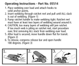
SAIL NUMBER POSITIONING
1. Lay the sail on a flat surface starboard side up.
2. Position the 1
st
number ( 3 ) 150mm in from the leech and 60mm
below the draft line.
3. The numbers should run parallel to the draft line.
4. Numbers should be 60mm apart.
150mm
from leech
60mm apart
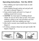
5. Turn over the sail
6. Position the GBR
starting with the R
180mm from the leech
7. The GBR is 60mm
above the draft line.
8. The letters are 60mm
apart.
9. Position the sail nos
60mm underneath and
parallel to the numbers
on the opposite side.
10. The numbers should be
put on so that they are in
line with the numbers on
the opposite side of the
sail.
11. This will be approx 200mm from the leech.

12. The starboard side GBR
should be positioned
60mm above the port
side letters and parallel
to them.
13. The letters should sit
above the port side
letters starting with the G
14. The gap between the
letters is 60mm.

SHROUD LAYOUT
V2 / D4 (Cap shroud )
VI / D3 main
shroud
D2
D1
Lowers
D shrouds are diagonals, V shrouds are verticals
V1 / D3 is a continous length, V2 / D4 is a continous length.

ASSEMBLY OF THE MAST
1. The mast will be supplied flat packed and will
require some tools to assemble:
- Posidrive screw driver
- Small adjustable spanner x 2 ( or mole
grips ) Care required if using mole grips
as these can mark the fittings)
- Electrician / small screwdriver
- Tape measure 5meters
- Rig tension gauge (recommended)
- Plastic tape
2. The shrouds and halyards will all be in position
on the mast and will just require unwrapping.
3. The 2 sets of spreaders and the backstay whip
are taped to the mast.
4. The backstay whip has 3 pre-drilled holes and
is attached to the crane at the top of the mast.
The screws are supplied in the crane.
5. The spreader is fixed with no
adjustment. They are marked port
and starboard and simply attached
with two clevis pins and rings.
Ensure that these are taped up.
6. Measure the V2 / D4 ( Cap shrouds ) and adjust the bottle screw to give
a distance of 4440mm from the bearing surface of the pin to the bearing
surface of the T terminal on this shroud. This measurement may vary
slightly and is a starting guide, the objective is to achieve 4” prebend.

7. Fit the V2 / D4 ( Caps)shrouds and the V1 / D3 ( main shrouds) to the T
terminals first and then to the spreaders. The Ferrules on the main
shrouds are located as shown. Locate the Main shrouds into the spreader
end by removing the clevis pin and slotting into position. The clevis pin
then fits to the bottle screw on the Cap shroud.
Caps
4440mm
8. Tape up the main shroud as
shown. This holds the feral in
position whilst fully taping the
end of the spreader assembly.
9. Lock the bottle screw by
inserting a small screwdriver
and turning anti clockwise.
10. V1 / D3 shrouds - Adjust the bottle
screws so that they are the same length
and showing approx 20mm of thread.
(loose, this will be set up once the rig is
raised and tensioned)
11. Fit the D2 and the D1shrouds and
repeat getting the lengths equal.
12. Ensure that all pins and rings are
taped up. The mast is now ready for stepping.

RAISING THE MAST
1. The rig in transit position. The mast support is positioned at the granny
2.
. The mast and cradle are
ack of
ft
4. ould always
5. hould not
. The mast step bolt should then be
rails. This will be moved to the back of the boat when raising the mast.
The trailer should be chocked or lower the rear supports before
assembly of the mast.
3
moved aft. The mast
cradle should be
positioned at the b
the boat as shown, and
then the mast is moved a
to position the mast heel to
the step.
The mast sh
be positioned on the port
side of the keel.
The Lifting post s
ast be in position for lifting the m
as it could foul the rigging.
5
tightened so that the Nilock on the
nut is engaged.

6. Attach the shrouds and D2
main
. Ensure that all the shrouds are
. Tie a bowline in the jib
t the winch hook
tach the hook to the
1. Pull in the slack on the jib halyard.
2.Tie a safety knot in the jib
cleat.
3. Ensure that the cleat is in the
ar of
rd is
5. The Winch strap must be positioned on
shrouds. The lowers should re
off at this stage.
7
in their terminals.
8
halyard.
9. Pull ou
until the hook is reaching
the middle of the granny
rails.
10. At
jib halyard.
1
1
halyard close to the spin lock
1
cleated position, AND THE KNOT IS
CLOSE TO THE CLEAT.
14. Check the rigging is cle
obstructions and that the jib halya
not rapped around anything.
1
the starboard side of the gennaker pole.

16. One person is to operate the winch whilst a second person lifts the mast
halyard to
8. With the mast in the upright position – take the
9. Using
e winch
w
ch
LEASE NOTE; The first time the rig
the
s
from the cradle and walks up the boat whilst the winch is reeled in.
17. A third person can assist in the operation by using the gennaker
assist the mast erection.
1
gennaker halyard and secure it to the trailer. Cleat
off the gennaker halyard at the mast. This is purely
as a safety line whilst attaching the forestay.
1
th
SLOWLEY
engage the forestay clevis pin. Atta
the ring to the pin and then release the
winch. DO NOT OVERWIND THE
WINCH.
ind the rig forward to
set up of the rig, the bottle screws can
of raising the mast will enable the rigs
P
is assembled the bottle screws will be
in their extended position prior to
setting up the rig. Subsequently to
be left set in position and this method
ettings to remain.

SETTING UP THE MAST
The objective is to set the mast up to have
e correct amount of mast bend and
nsion in the shrouds. The forestay is a fixed
an
as the spreaders are factory set.
s to
he D1 shr are left detached in the initial stages of the set up.
/ D3 Main shroud = 270kg ( 37.5 on a
)
ensions may vary to achieve the
th
te
length and is controlled by the class rules, so
mast rake is pre set. You are looking for
even bend for and aft and straight side-to-
side.
The tension in the V1 / D3 shrouds and
the D2 shrouds control the mast bend,
Adjustment of the tension on the
shrouds is done via the bottle screws.
To tighten and loosen you will require
an adjustable spanner to hold the
swage at the top of the bottle screw
and insert a screwdriver to turn the
bottle screw body in the required
direction. When adjusting the bottle
screws it is a good idea to keep a
record of the number of turns so a
keep the shrouds the same length.
oudsT
Rig Tension settings;
V1
Loos PT1 metric gauge
D2 Shroud = 213kg ( 34 on Loos gauge )
T
correct mast bend.

The mast bend should be approx 4” at the
main spreaders.
y pulling the main halyard tight and holding
e
give you a good guide.
e
p holding the halyard away.
ack.
all
screwdriver and rotating the grub
rew anticlockwise to secure bottle
he backstay control can be used to induce
ore mast bend if required to flatten the sail.
The lowers
B
the halyard to the aft face of the mast abov
the gooseneck will
The halyard will be 4 ½ – 5” at spreader
height – this is allowing for the sheave at th
to
The mast section depth is 4” and is a useful
guide comparison.
D1 shrouds can now be attached and should be just sl
Lock the shrouds by using a sm
sc
screw.
T
m

VANG SET UP
1. Attach boom to mast.
2. Attach the Gnav bar to the mast.
. Attach Gnav
the boom.
. The Gnav tackle ( supplied with Gnav bar )
hould be attached by taking the only free
nd of the black / green fleck rope and
he top spinlock
6. Attach the pulley and shackle on the
black / green rope to the lower D ring /
3
to
4
s
e
feeding this thru the sheave on the top of the
boom.
5. Feed this rope thru the pulley on the aft
face of the mast and then to t
leat. c
webbing on the mast.

7. Attach the large pulley and
hackle to the Gnav car on the
oom.
8. Attach the last pulley and
hackle to the uppermost D
ng and webbing on the mast
s
b
s
ri
Vang assembled

GENNAKER BAG
1. Ensure that the hatch is in the
closed position before sailing
2. Hatch shows the handle in the
3. Insert the tube on the gennaker bag
onto the bobble first
board end and secure the
ont of the bag to the
closed position
4. Insert the star
elastic to the clip
5. Secure hook on the fr
clip on the boat

JIB SHEET AND CUNNINGHAM SET UP
1. The jib sheets are a continuous
system.
ugh the spring and
shackle at the base of the jib
4.
2. Shackle the two blocks to the jib
clew.
3. Dead end one end of the jib
sheet thro
car pulley.
Feed the other end of the jib
sheet up
thru the block on th
jib tack and then back thru the
5.
the deck.
e
block on the track.
The sheet is then led back to
the ratchet block on
6. The sheet is then led across the boat and led thru the ratchet block,
7. Thru the jib car block
8. to the jib block and back to the jib car block where it is secured with a
dead end knot.

JIB CUNNINGHAM
1. The jib Cunningham is
controlled from the cleat at
the side of the mast on the
l
stay and
eye at the tack of the jib.
back
2. The jib Cunningham is led from the
port side of the bow fitting to the
port side. This is a usefu
control if used in
conjunction with the jib
halyard to raise and lower
the jib on the fore
fine tune the sheeting
angle
3. Thru the tack eye and to the turning
block on the starboard side of the
bow fitting. This then goes
thru the tack eye and dead ends at
the Becket on the port side block.
/