Wavetronix Click 110 User guide

Type
User guide

Wavetronix Click 110 is a 4-channel contact closure card designed for use with Wavetronix SmartSensors. It offers various capabilities to enhance traffic monitoring and management systems:

  • Vehicle Detection: The Click 110 reliably detects vehicles passing through its connected loop sensors.

  • Fault Indication: Four LEDs for each channel provide real-time fault status, helping identify and troubleshoot any issues promptly.

  • Configuration Options: The device can be configured using DIP switches for input/output mapping, baud rates, and outstation mode.

  • Daisy-Chaining: Multiple Click 110 cards can be daisy-chained together, simplifying installation and reducing cabling.

1 Mount and connect the device
www.wavetronix.com
801.734.7200
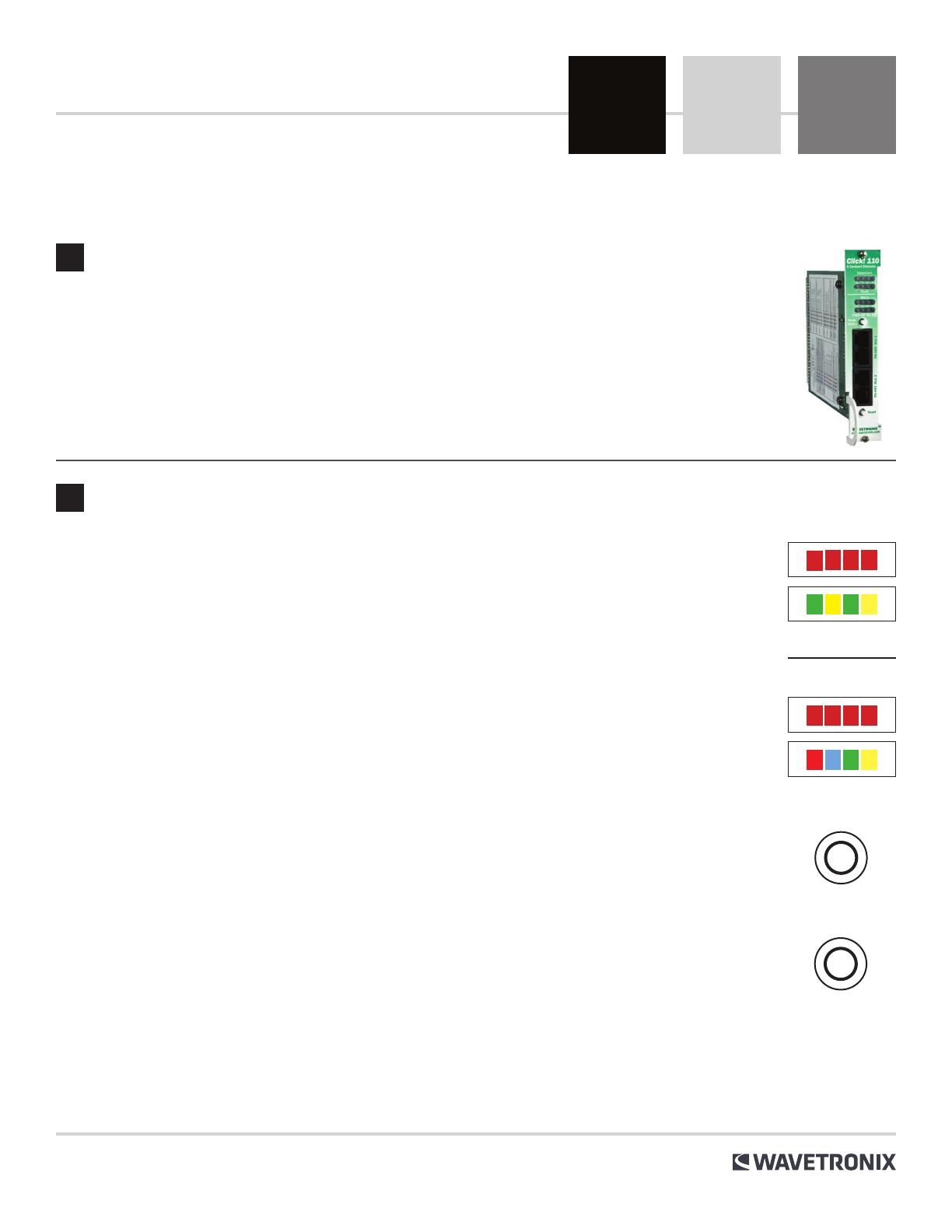
Click 110 Contact Closure
INSTALLATION QUICK START GUIDE
Use the following steps to install the Click 110 rack card:
1 If you’re using hardware configuration, set all DIP switches before installing Click 110 devices (see step 3).
2 Insert the card into the rack and daisy-chain all the cards in your installation together using short RJ-11
jumper cables.
3 Connect the first Click 110 card to the SmartSensor via a Click 200 with an RJ-11 patch cord.
Note. Bus 1 should be used to connect to the sensor and bus 2 for configuration.
Detection (Channel) LEDs
These LEDs light up to indicate vehicle detection.
Fault indicator LEDs
Four green and yellow LEDs numbered 1–4, each representing the channel with the corre-
sponding number.
˽Illuminated green LED – Indicates a no-fault condition.
˽Illuminated yellow LED – Indicates a fault condition that has existed for less than one minute.
˽Extinguished LED – Indicates a fault condition that has existed for more than one minute.
Level 2 LEDs
These LEDs are o.
Level 1 LEDs
˽Red (PWR) – Indicates the presence of power to the device.
˽Blue (MF) – Illuminates when the master fault output is in the no-fault condition. The LED
is extinguished in the fault condition.
˽Green (TD) – Indicates serial communication transmit data (from the Click 110) on either RS-
485 bus 1 or RS-485 bus 2.
˽Yellow (RD) – Indicates serial communication receive data (to the Click 110) on either RS-
485 bus 1 or RS-485 bus 2.
Push buttons
˽Mode switch – Allows you to cycle through and select menu and configuration options.
˽Reset switch – Allows you to reboot the Click 110. A reboot is one way to clear a latched fault condition. The other way is
to have the outstation’s back end software reboot the card.
DIP switches
Located on the lower part of the circuit board. These switches allow you to configure the device (see Part 3 of this guide).
2 Understand the device’s configuration features
Mode
Menu
Fault
Detection
Level 2
Level 1
Reset
The Click 110 is a 4-channel contact closure card for use with Wavetronix SmartSensors. For more information about this prod-
uct, visit wavetronix.com.
3 Configuring the DIP switches
The Click 110 should be configured using the DIP switches, The DIP switches on the circuit board can be used to change
input mapping and the baud rates used for bus 1 and bus 2. These parameters can also be changed using the two other
configuration options.
Note. Using the DIP switches to configure puts the Click 110 into hardware mode. In hardware mode the settings can be
viewed, but not changed via Click Supervisor and the front panel menu.
Look at the figure below to see how to set the switches in order to configure the parameters. To turn a switch on, flip it up.
Baud rate for Bus 1 and Bus 2
This function lets you set the baud rate for bus 1 and bus 2. The two buses can be configured separately. Flip the switches up
and down according to the diagram to set the baud rate for each bus. All cards should be set to 9600 baud.
Channel output mapping
Any combination of outputs can be enabled. A disabled output will never enter the detection state and will never indicate a fault
condition. Due to limited space on the faceplate side label, not all combinations of enabled and disabled channels are listed.
Channel input mapping
This function lets you map four of the input data channels coming from the sensor to the output channels on the device. The
outputs are assigned sequentially, so if you select 13-16, then input 13 will be mapped to channel 1 and input 14 will be mapped to
channel 2. The table below shows an example of a 10 and 6 lane setup.
Note. The lanes need to be renamed from the default name of “Lane_01” to “#01” using the SSMHD software. Please check the
outstation information card to confirm lane assignments as there can be some variation.
WX-500-0240
Once all the Click 110 cards have been inserted into the rack, connect the Click 200 with the long RJ-11 cable into the top RS-
485 bus (Bus 1) of the Click 110 card in slot 1. Multiple Click 110 cards can be daisy-chained together from the bottom connec-
tion of Bus 1 to the top connection of Bus 1 on the next Click 110 card in the rack. Bus 2 is not used for regular detections and
should remain empty and unconnected.
No connections are made between the SmartSensor HD and the traditional loop connections on the rear of the outstation.
These remain empty.
When the cards are configured and connected properly, the LEDs on each card will turn on when vehicles are detected.
Additional information on the Click 110 LEDs can be found in the Click 100-400 Series User Guide.
4 Connections
Carriageway Lane name Loop pair Channel setup
A
#01 1-2 1-4
#02 3-4 1-4
#03 5-6 5-8
#04 7-8 5-8
#05 9-10 9-12
B
#10 19-20 17-20
#09 17-18 17-20
#08 15-16 13-16
#07 13-14 13-16
#06 11-12 9-12
Carriageway Lane name Loop pair Channel setup
A
#01 1-2 1-4
#02 3-4 1-4
#03 5-6 5-8
B
#06 11-12 9-12
#05 9-10 9-12
#04 7-8 5-8
Outstation mode
This function allows you to define which type of outstation the Click 110 will be installed in.
Fault latch
This function allows you to define how the fail-safe fault functions and can only be set with the dip switches. The Click 110 will
stay in fail-safe mode, unless fault latching is disabled, at any point after the system has been in fail-safe for over one minute
even if the Click 110 receives data from the sensor and requires a reset to clear the fail-safe state. The Fault latching setting
should be disabled. However, some areas may request that the fault latch be enabled so the RTMC can visit or inspect sites
that have gone into fault.
© 2022 Wavetronix LLC. All rights reserved. Protected in the US by patents viewable at www.wavetronix.com/en/legal. Protected by Canadian Patent Nos. 2461411; 2434756; 2512689; and European Patent Nos. 1435036; 1438702;
1611458. Other US and international patents pending. Wavetronix, SmartSensor, Click, Command and all associated logos are trademarks of Wavetronix LLC. All other product or brand names as they appear are trademarks or
registered trademarks of their respective holders. Product specifications are subject to change without notice. This material is provided for informational purposes only; Wavetronix assumes no liability related to its use.
  • Page 1 1
  • Page 2 2
  • Page 3 3

Wavetronix Click 110 User guide

Type
User guide

Wavetronix Click 110 is a 4-channel contact closure card designed for use with Wavetronix SmartSensors. It offers various capabilities to enhance traffic monitoring and management systems:

  • Vehicle Detection: The Click 110 reliably detects vehicles passing through its connected loop sensors.

  • Fault Indication: Four LEDs for each channel provide real-time fault status, helping identify and troubleshoot any issues promptly.

  • Configuration Options: The device can be configured using DIP switches for input/output mapping, baud rates, and outstation mode.

  • Daisy-Chaining: Multiple Click 110 cards can be daisy-chained together, simplifying installation and reducing cabling.

Ask a question and I''ll find the answer in the document

Finding information in a document is now easier with AI