Wavetronix Click 512 User guide

Type
User guide

Wavetronix Click 512 is an advanced vehicle monitoring device that provides lane, speed, length, and class information from a SmartSensor HD. It compares detected data to predetermined thresholds and activates digital outputs or contact closures based on the vehicle characteristics. The device can be configured using Click Supervisor software and features various modes like Run, Device Setup, and Serial Convert. With its versatile communication options, including RS-485, RS-232, and RJ-11, the Click 512 seamlessly integrates into traffic monitoring systems.

Wavetronix Click 512 is an advanced vehicle monitoring device that provides lane, speed, length, and class information from a SmartSensor HD. It compares detected data to predetermined thresholds and activates digital outputs or contact closures based on the vehicle characteristics. The device can be configured using Click Supervisor software and features various modes like Run, Device Setup, and Serial Convert. With its versatile communication options, including RS-485, RS-232, and RJ-11, the Click 512 seamlessly integrates into traffic monitoring systems.

www.wavetronix.com
801.734.7200
Click 512 Vehicle Alert
QUICK START GUIDE
1 Mount the device
The Click 512 mounts over a T-bus for power and communication:
1 If the Click 512 was shipped with the T-bus connector at-
tached, remove the connector from the module.
2 Snap the connector onto the DIN rail by positioning it over
the rail with the male connector pointing to the right. Hook
one arm over the edge of the DIN rail and press down on the
other arm until it snaps into place.
3 Connect the T-bus connector to the rest of the T-bus by slid-
ing them together until you hear them snap into place.
4 Mount the Click 512 onto the DIN rail: position it properly over the T-bus connector, hook the lip over the lower edge of
the DIN rail, and use a rocking motion to snap the module into place.
If you are using a Click 200 surge protector with the Click 512, power and communication are provided to the Click 512
through the T-bus (see the Click 200 Quick Start Guide). If you don’t have a Click 200 surge protector, use the following steps
to wire power and communication into the Click 512:
1 Plug a T-bus 5-screw terminal block into the first T-bus
connector.
2 Wire DC power (10–30 V) from the power supply into the
first screw terminal on the 5-screw terminal block; wire
-DC into the second screw terminal.
3 Connect RS-485 communication (+485, -485, and GND) to
either the remaining three screw terminals on the 5-screw
terminal block or to the screw terminals in the pluggable
screw terminal block on the top of the Click 512 (see labels
for correct wiring).
The Click 512 has three other communication ports.
˽RJ-11 jack – Connect a jumper cable here for RS-485 communication
˽DB-9 connector – Connect a straight-through cable here for RS-232 communication
˽RS-232/RS-485 terminals – On top of device; usually not used
Vehicle information from the SmartSensor HD can be monitored through either digital output on the first block on the bot-
tom of the device. If you are wiring output 1 directly to a contact closure input device, wire the output O1+ and O1- (common
ground) to the input terminals. Do the same for output 2, and if you are using outputs 2–8, you will need to wire to a Click
100/112/114 contact closure card. If you need to wire to a relay, consider the Click 120.
3 Wire contact closures
2 Wire power and communication
Red (+DC)
Black (-DC)
White (+485)
Blue (-485)
Drain (GND)
The Click 512 monitors lane, speed, length, and class information from a SmartSensor HD and then compares the detected
data to a set of predetermined threshold values. For more information about this product, visit wavetronix.com.
Select a task or operation function by navigating through the main menu (multicolored LEDs) and the submenus (yellow and
red LEDs) using the push-button as described below:
1 Enter the main menu and cycle through it by holding the push-button down.
2 Release the push-button once the cycle reaches the desired mode.
3 Press the bush-button again to select the mode. Once selected, the mode will either start running or the first submenu
(yellow LEDs) will start.
4 Hold the push-button to cycle through the first submenu.
5 Release the push-button once the desired sub-menu selection is displayed.
6 Press the push-button again to select the function. The function will now run.
Click Supervisor is used to configure the Click 512. Follow these steps to install and connect to Click Supervisor:
1 Download the setup file from www.wavetronix.com (under Support) and double-click on the file to run the setup wizard.
Follow the steps to install.
2 Manually copy the 512 driver files into the “Program Files\ClickHome\512” directory.
3 Using the DB-9 connector on the front of the module, make a connection between the Click 512 and the computer.
Use Device Setup mode to configure threshold values and other settings using Click Supervisor:
4 Hold the push-button down, then release when the green LED comes on.
5 Press the push-button to select. The red and green LEDs will turn on.
6 Run Click Supervisor and select Communication. This screen lets you pick the type of connection, serial or IP. The Click
512 must be configured using serial communication.
5 How to use the push-button to navigate through mode and task menus
6 Device Setup mode
4 Use on-device configuration features
Next, use the Click 512’s configuration feature to make sure it is wired and
working properly. The device has four LEDs that monitor device activity
and help you select tasks and operating modes. It also has two banks of
LEDs: one of yellow LEDs that represent submenu 1 and one of red for
submenu 2. Check the LEDs to make sure the device has power.
The Click 512 also has a push-button, labeled Mode Switch, used for
selecting tasks and operating modes.
LED activity-indicating functions:
The blue LED has no activity-indicating function
Red – Device has power
Green – Device is transmitting data
Yellow – Device is receiving data
Once in Device Setup mode (see part 6), ensure that the contact closure device can communicate with the Click 512. If you
are using a Click 100 or Click 112/114, set it up in AC (Actuation) mode. Once the contact closure device is set up, wire into the
contact closure output terminals on the device.
Sub Menu 1
Yellow LEDs
Red LEDs Sub Menu 2
Button
Main MenuMulticolored LEDs
7 Configure the module
8 Run mode
9 Serial Convert mode
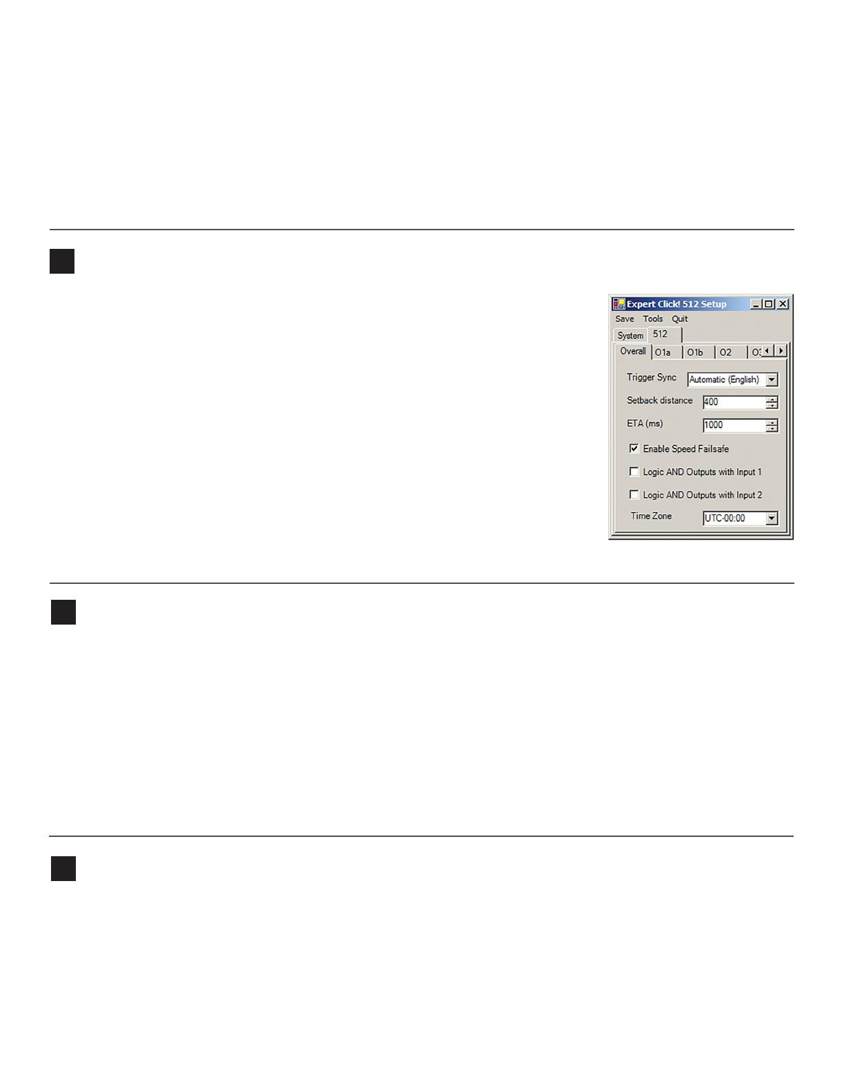
Overall Tab
˽Trigger Sync – Sets the method of trigger synchronization. The Automatic (English)
option is recommended.
˽Setback Distance – Distance between the sensor and a downstream location on the
roadway. The typical distance may be 400 feet between the sensor and a downstream
warning sign.
˽ETA – Enter the ETA at which the output should activate; for example, 2000 ms before
reaching a warning sign. Enter “0” if you are not using the ETA trigger method.
Output Tabs
˽Lower/Upper Lane Limit – Allows you to filter which lanes are mapped to this output.
˽Max Speed – Sets the default value for the maximum speed threshold.
˽Max Length – Sets the default value for the maximum length threshold.
˽Duration – An output stays on for at least the number of milliseconds specified here.
For example, if the output activates with an ETA of 2000 ms, you may want the duration
to be 2000 ms so that the output stays on until the motorist reaches a warning sign.
Once the device has been configured, set it to Run mode to start retrieving vehicle data. In run mode the Click 512 listens
to data from the SmartSensor HD on the RS-485 T-bus port and compares the detected values to the thresholds set in Click
Supervisor.
Note. By default, the Click 512 communicates to SmartSensor HD at 9600 bps.
1 Hold the push-button down, then release when the blue LED turns on.
2 Press the push-button to select. The red and blue lights will turn on, and the yellow light will flash.
3 As the device listens to the SmartSEnsor HD, one of the two submenu LEDs will light up”
˽Yellow 1-4 – These LEDs light up when outputs 1–4 are activated.
˽Red 1-4 – These LEDs activate when outputs 5–8 are activated.
Serial Convert mode is the third menu option. This mode acts as a serial converter between all the dierent communications
ports, which may be useful for debugging communication links.
1 Hold the push-button down, then release when the yellow LED turns on.
2 Press the push-button to select. The red and yellow LEDs will turn on. The mode is now running.
7 Click Settings to make any necessary changes to the settings, such as the port. Click OK to return to the communication
screen, then click Connect. Keep the Click ID set to 0.
8 In the next screen, Click Supervisor will display all the devices it discovers. When the Click 512 appears, select it and click
Select. Click Supervisor will connect to the device.
9 Click Setup Click and select Expert from the driver list.
10 When the driver is loaded, click on the 512 tab. You will then see tabs labeled Overall, O1a, O1b, O2, O3, O4,...O8.
Use the Device Setup mode to:
11 Autobaud the contact closure card (see the Quick Start Guide)
12 Select Actuation mode.
10 Reset
To rest the Click 512, follow the steps below.
1 Hold the push-button down, then release when the red LED starts flashing.
2 Press the push-button to select. The first yellow LED will turn on to let you use that submenu.
3 Hold down the push button again to cycle between the following options:
˽Yellow 1 – Resets all setting except Serial Number and XML variable map.
˽Yellow 2 – Resets all settings except Serial Number.
4 Release when you reach the one you want. Press the push-button to select.
After the device is reset, it will return to the last mode that it was in.
WX-500-0196
© 2022 Wavetronix LLC. All rights reserved. Protected in the US by patents viewable at www.wavetronix.com/en/legal. Protected by Canadian Patent Nos. 2461411; 2434756; 2512689; and European Patent Nos. 1435036; 1438702;
1611458. Other US and international patents pending. Wavetronix, SmartSensor, Click, Command and all associated logos are trademarks of Wavetronix LLC. All other product or brand names as they appear are trademarks or
registered trademarks of their respective holders. Product specifications are subject to change without notice. This material is provided for informational purposes only; Wavetronix assumes no liability related to its use.
  • Page 1 1
  • Page 2 2
  • Page 3 3
  • Page 4 4

Wavetronix Click 512 User guide

Type
User guide

Wavetronix Click 512 is an advanced vehicle monitoring device that provides lane, speed, length, and class information from a SmartSensor HD. It compares detected data to predetermined thresholds and activates digital outputs or contact closures based on the vehicle characteristics. The device can be configured using Click Supervisor software and features various modes like Run, Device Setup, and Serial Convert. With its versatile communication options, including RS-485, RS-232, and RJ-11, the Click 512 seamlessly integrates into traffic monitoring systems.

Ask a question and I''ll find the answer in the document

Finding information in a document is now easier with AI