Page is loading ...

MANUAL PART #: A MANUAL PART #: A
OWNER’S MANUAL
MODEL XP ISO-Flex 2700
Single Sliding Cooler/Freezer Door
MANUAL PART #: A

ASI DOORS, INC. (800) 558-7068 asidoors.com
GENERAL
INFORMATION
GENERAL INFORMATION
. . . . . . . . . . . . . . . . . . . . . . . 3-8
Safety Practices . . . . . . . . . . . . . . . . . . . . . . . . . . . . . . . . . . . . 3
Warranty Policy . . . . . . . . . . . . . . . . . . . . . . . . . . . . . . . . . . . . 5
Crates and Contents . . . . . . . . . . . . . . . . . . . . . . . . . . . . . . . . . . 6
Warnings . . . . . . . . . . . . . . . . . . . . . . . . . . . . . . . . . . . . . . . . 8
XP MANUAL INSTALLATION
. . . . . . . . . . . . . . . . . . . 8-26
Door Measurements . . . . . . . . . . . . . . . . . . . . . . . . . . . . . . . . . . 8
Face Frame Installation . . . . . . . . . . . . . . . . . . . . . . . . . . . . . . . . . 10
Header Installation . . . . . . . . . . . . . . . . . . . . . . . . . . . . . . . . . . . 11
Panel Installation . . . . . . . . . . . . . . . . . . . . . . . . . . . . . . . . . . . . 12
Floor Hardware Installation . . . . . . . . . . . . . . . . . . . . . . . . . . . . . . . 14
Door Adjustments . . . . . . . . . . . . . . . . . . . . . . . . . . . . . . . . . . . 15
Wall Track Installation . . . . . . . . . . . . . . . . . . . . . . . . . . . . . . . . . . 19
Electrical Controls . . . . . . . . . . . . . . . . . . . . . . . . . . . . . . . . . . . 21
Safety Practices . . . . . . . . . . . . . . . . . . . . . . . . . . . . . . . . . . . . . 25
Start-Up & Operation . . . . . . . . . . . . . . . . . . . . . . . . . . . . . . . . . . 26
MAINTENANCE
. . . . . . . . . . . . . . . . . . . . . . . . . . . . 27-32
Troubleshooting . . . . . . . . . . . . . . . . . . . . . . . . . . . . . . . . . . . . 27
Preventative Maintenance . . . . . . . . . . . . . . . . . . . . . . . . . . . . . . . 29
REPLACEMENT PARTS
. . . . . . . . . . . . . . . . . . . . . . . 30-55
Instructions for Ordering . . . . . . . . . . . . . . . . . . . . . . . . . . . . . . . . 30
Door Identification . . . . . . . . . . . . . . . . . . . . . . . . . . . . . . . . . . . 31
ID Tag Location . . . . . . . . . . . . . . . . . . . . . . . . . . . . . . . . . . . . . 31
Manual Header Assemblies . . . . . . . . . . . . . . . . . . . . . . . . . . . . . . . 32
Power Header Assemblies . . . . . . . . . . . . . . . . . . . . . . . . . . . . . . . 34
Manual Header Shrouds . . . . . . . . . . . . . . . . . . . . . . . . . . . . . . . . . 36
Power Header Shrouds . . . . . . . . . . . . . . . . . . . . . . . . . . . . . . . . . 37
End Top Assemblies . . . . . . . . . . . . . . . . . . . . . . . . . . . . . . . . . . . 38
Trolley Assemblies . . . . . . . . . . . . . . . . . . . . . . . . . . . . . . . . . . . 39
Door Panel Assemblies . . . . . . . . . . . . . . . . . . . . . . . . . . . . . . . . . 40
Face Frame Assemblies . . . . . . . . . . . . . . . . . . . . . . . . . . . . . . . . . 42
Floor Hardware . . . . . . . . . . . . . . . . . . . . . . . . . . . . . . . . . . . . . 43
Drive Assembly . . . . . . . . . . . . . . . . . . . . . . . . . . . . . . . . . . . . . 44
Control Panel Assembly . . . . . . . . . . . . . . . . . . . . . . . . . . . . . . . . . 45
Wall Track Assemblies . . . . . . . . . . . . . . . . . . . . . . . . . . . . . . . . . . 46
Heat System (Freezer) Option . . . . . . . . . . . . . . . . . . . . . . . . . . . . . . 48
Kick Plate . . . . . . . . . . . . . . . . . . . . . . . . . . . . . . . . . . . . . . . 48
Miscellaneous Options . . . . . . . . . . . . . . . . . . . . . . . . . . . . . . . . . 49
Control Panel . . . . . . . . . . . . . . . . . . . . . . . . . . . . . . . . . . . . . . 50
ADDENDUM
. . . . . . . . . . . . . . . . . . . . . . . . . . . . . . 51-55
Manual last updated on: October 4, 2022 3:59 PM

ASI DOORS, INC. (800) 558-7068 asidoors.com
Safety Practices
This is a safety alert symbol. It is used to alert you to potential personal injury
hazards. Obey all safety messages that follow this symbol to avoid possible
injury or death.
WARNING indicates a potentially hazardous situation which, if not avoided, could result in
death or serious injury.
CAUTION indicates a potentially hazardous situation which, if not avoided, may result in minor
or moderate injury.
CAUTION used without a safety alert symbol indicates a potentially hazardous situation which,
if not avoided, may result in property damage.
NOTE explains general information.
DANGER indicates an imminently hazardous situation which, if not avoided, will result in death
or serious injury.
NOTE
GENERAL
INFORMATION

ASI DOORS, INC. (800) 558-7068 asidoors.com
Warning read these safety practices before installing, operating or servicing the SLIDING
door. Failure to follow these safety practices could result in property damage, death or
serious injury.
READ AND UNDERSTAND ALL WARNING LABELS AND OPERATING INSTRUCTIONS IN THIS
MANUAL BEFORE OPERATING THE SLIDING DOOR. If you do not understand the instructions,
ask your supervisor to teach you how to use the SLIDING door.
Safety Practices (cont’d)
1. Do not operate the door while under the influence of drugs or alcohol.
2. Do not use the door if it looks broken or does not seem to work properly. Advise your supervisor at
once.
3. Stay clear of the door when it is moving
4. Keep hands, feet and head clear of the door at all times.
5. Do not operate the door with equipment, material or people directly inside door opening.
6. Disconnect power before performing any electrical or mechanical service, cleaning or other mainte-
nance on the door. OSHA requires disconnect to be properly tagged and locked out during all mainte-
nance or service of equipment. With the power supply disconnected, always verify using a volt meter.
7. All electrical troubleshooting or service must be completed by a qualified electrician or service
person and must meet all applicable local, state, federal, international and other governing agency
codes.
8. When it is necessary to service the control box with power on, USE EXTREME CAUTION. Do not place
fingers or uninsulated tools inside the control box. Touching wires or other parts inside the enclosure
may cause electrical shock, serious injury or death.
9. It is your responsibility to keep all warning labels and instructional literature legible, intact and kept
with the door. Replacement labels and literature are available from ASI Doors, Inc. or its
representatives.
10. If you have any questions, contact your supervisor or your local ASI Doors, Inc. representative for
assistance.
11. Train all service and personnel using or near door on intended use(s) and operation of the door.
12. Failure to operate the door as intended, as described, or heed any warning may result in equipment
damage, property damage, serious bodily injury or death.
GENERAL
INFORMATION

ASI DOORS, INC. (800) 558-7068 asidoors.com
Warranty Policy
ASI Doors (herein called “ASI”) warrants solely for the benefit of its customer that each door system
manufactured by ASI (each a “Door System”) will be free from defects in material and manufacture for a
period of one (1) year from the date of original shipment by ASI. The following models receive a similar
two (2) years from date of shipment warranty: 109, 209, 120-125, 1240-125-, 1240SS-1250SS, 1260-1270,
1260SS-1270SS, 130-135, 140-150, 160-170, 220-225, 220SS-225SS, 230-235, 230SS-235SS. In all instances
warranty labor is covered for a period of one (1) year from the date of original shipment.
The foregoing limited warranty shall not apply to defects that result from improper installation, abuse,
misuse, alteration, modification, or failure to maintain the Door System in accordance with the ASI
Owner’s Manual. Periodic maintenance and adjustment of the Door System as described in the ASI
Owner’s Manual are the sole responsibility of the customer. All claims for defects must be made to
ASI within thirty (30) days a er the defect is discovered or should, with reasonable care, have been
discovered. THE FOREGOING LIMITED WARRANTY CONSTITUTES THE EXCLUSIVE WARRANTY OF ASI
WITH RESPECT TO THE DOOR SYSTEM. ASI EXPRESSLY DISCLAIMS ALL OTHER GUARANTEES OR
WARRANTIES—WHETHER EXPRESSED, IMPLIED, OR STATUTORY, INCLUDING BUT NOT LIMITED TO
ANY IMPLIED WARRANTY OF MERCHANTABILITY AND FITNESS FOR A PARTICULAR PURPOSE.
If a Door System does not comply with the foregoing limited warranty, and a claim is made by customer
within the warranty period, ASI will, at the option of ASI, either repair or replace any defective equipment
or parts free of charge and pay the reasonable labor costs to repair or replace the defective equipment or
parts if within the defined warranty period. The remedy of repair or replacement shall be the exclusive
and sole remedy for any breach of the foregoing limited warranty.
ASI SHALL NOT IN ANY EVENT BE LIABLE FOR ANY INCIDENTAL, INDIRECT, SPECIAL, EXEMPLARY OR
CONSEQUENTIAL DAMAGES OF ANY KIND, INCLUDING WITHOUT LIMITATION ANY LOST PROFITS,
ARISING FROM THE SALE OR USE OF THE DOOR SYSTEM, OR FROM ANY OTHER CAUSE WHATSOEVER,
WHETHER THE CLAIM GIVING RISE TO SUCH DAMAGES IS BASED UPON BREACH OF WARRANTY
(EXPRESSED OR IMPLIED) BREACH OF CONTRACT, TORT, STRICT LIABILITY OR ANY OTHER THEORY
OF LIABILITY, EVEN IF A PARTY HAS BEEN ADVISED OF THE POSSIBILITY THEREOF, AND REGARDLESS
OF ANY ADVISE OR REPRESENTATION THAT MAY HAVE BEEN RENDERED BY ASI CONCERNING THE
SALE OR USE OF THE DOOR SYSTEM.
At ASI’s request, customer shall return to ASI for inspection any Door System for which a warranty claim
has been made, F.O.B. ASI’s facility with freight prepaid. The customer is responsible for any removal
costs.
The customer shall comply with the following procedures in filing a warranty claim with ASI:
1. Notify ASI of any and all defects in writing with photographic evidence. ASI will review the warranty
request and issue a Returns Merchandise Authorization (RMA) form if the defective parts need to be
returned to ASI for inspection and verification. The RMA form must accompany any materials returned for
warranty consideration.
2. All replacement parts or equipment will be invoiced to the customer. Upon verification by ASI that the
Door System is defective, ASI will issue a full credit to customer for the replacement parts or equipment.
3. If outside labor is needed to install the replacement parts or equipment, ASI requires a written
estimate of the labor charges in advance so ASI may approve the labor charges and issue a purchase
order. ASI will not accept any labor charges unless previously approved in writing and accompanied by
the ASI purchase order number.
(Rev 12/21)
GENERAL
INFORMATION

ASI DOORS, INC. (800) 558-7068 asidoors.com
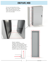
Crates and Contents
GENERAL
INFORMATION
Figure 1: Crates and Contents
NOTE: Contents of crates #1 & #2 may be
combined into one crate for shipping
NOTE

ASI DOORS, INC. (800) 558-7068 asidoors.com
Crates and Contents Continued
GENERAL
INFORMATION
Description - Manual Qty.
Installation Instructions 1
Sales Drawing 1
Trailing Edge Roller Assembly 1
Lead Edge Roller Assembly 1
Misc. Hardware Bag 1
Loose Parts
On receipt of shipment, check that you have received
the correct number of pieces. All cartons are labeled
as to their contents. Inspect each carton for damage in
shipment. If damaged, report at once! ASI suggests that
only one carton be opened at a time as installed. This will
keep all units clean with less chance for damage. Loose
parts are in a parts box with header and casing. Header
and rail casing are attached to crate by lag screws.
Unscrew these to remove casing. The balance point
of the header casing is between the operator and the
centerline of the header.
Crate one will contain the door panel assemblies. Crate
two will contain the side frames, header assembly,
control box (Power Doors) and loose parts box (Figure 1).
For your protection, note any damages or shortages
on the carrier’s bill of lading before signing the bill for
receipt.
The installation of this door will require at least a
two man crew and a fork li . Select a fork li with
li ing height based upon the height of the door plus a
minimum additional two feet.
Note because of variances in the construction of
walls on which the door will be mounted,
fasteners are not supplied. For proper
anchoring of the door, we recommend the use of
thru-bolts. DO NOT remove door sections from
crate until you encounter the step in which they
are to be installed.
NOTE
Note
unless specifically called out as “Provided by
ASI”, installer is to provide all necessary mounting
hardware, anchors, inserts, hangers, supports and
equipment needed to install door in accordance
with final shop drawings and manufacturer’s
instructions.
Description - Power Cooler Qty.
Installation Instructions 1
Sales Drawing 1
Trailing Edge Roller Assembly 1
Lead Edge Roller Assembly 1
Misc. Hardware Bag 1
Label, Warning 4
Loose Parts
WARNING before mounting Door, review all Safety Practices as detailed in this manual.
Description - Power Freezer Qty.
Installation Instructions 1
Sales Drawing 1
Trailing Edge Roller Assembly 1
Lead Edge Roller Assembly 1
Misc. Hardware Bag 1
Label, Warning 4
Loose Parts

ASI DOORS, INC. (800) 558-7068 asidoors.com
Warnings
WARNING
observe the following instructions to reduce the risk of serious injury, or death.
1. READ AND FOLLOW ALL INSTALLATION INSTRUCTIONS.
2. Install on a properly prepared and constructed wall. Have qualified service personnel remove any existing
cables, spring assemblies, and other hardware OF AN EXISTING DOOR before installing the new ASI door.
3. Remove all pull ropes and remove, or make inoperative, all locks (unless mechanically and/or electrically
interlocked to the power unit) connected to the door before installing the operator.
4. A commercial/industrial door operator that has exposed moving parts capable of causing injury to persons or
employs a motor deemed indirectly accessible by virtue of its location above the floor shall include:
a. Door face frames (door opening height or “HIC”) must be 7’ 6” or above.
5. Do not connect the door operator to the source of power until instructed to do so.
6. Locate the control station: (a) within sight of the door, and (b) at a minimum height of 1.53 m (5 ) above
floors, landings, steps, or any other adjacent walking surface and (c) away from all moving parts of the door.
7. Install the entrapment warning placard next to the control station in a prominent location.
8. For products having a manual release, instruct the end user on the operation of the manual release.
IMPORTANT INSTALLATION INSTRUCTIONS!
DANGER
Do not install, operate or service this product unless
you have read and understand the Safety Practices, Warnings and
Installation and Operating Instructions contained in this manual.
Failure to do so could result in property damage, bodily injury or
death.
Note In this manual, doors shown will be right-hand
operators. For le -hand operator doors, positions of
some components will be the reverse of that shown.
NOTE
1 Measure door opening to verify door mounting
dimensions (Figures 3, 4, & 5). The Face Frames will
fit flush to the sides of the opening as shown
2 Be sure to read all warning labels before installation
(Figure 2).
Figure 3: Wall Clip Position - Frames with no Jamb or
Inside Trim
Figure 4: Wall Clip Position - Frames with Inside Trim
GENERAL
INFORMATION
Door Measurements

ASI DOORS, INC. (800) 558-7068 asidoors.com
Door Measurements Continued
INSTALLATION
DANGER
Do not install, operate or service this product unless
you have read and understand the Safety Practices, Warnings and
Installation and Operating Instructions contained in this manual.
Failure to do so could result in property damage, bodily injury or
death.
Note In this manual, doors shown will be right-hand
operators. For le -hand operator doors, positions of
some components will be the reverse of that shown.
NOTE
3 Check plumb and
square. Shim if
necessary (Figure
6). Header and side
frames must be on
same plane. Make sure
operator end is not
sagging.
4 Based upon the
dimensions in Figure
7, determine that door
will have su icient
wall space to slide
open.
PERFECTLY FLAT
CHECK
CHECK
Figure 5: Wall Clip Position - Frames with Jamb Capping
and Inside Trim
Figure 6: Checking Plumb and Square
Note Recheck frames and rail assembly to be sure they
are square. Check frames with straight edge to make
sure they are in the same plane. Check diagonally
across corners for square. Shim under the face frame as
required to the true plane and plumb. This step is
necessary to insure a tight door seal.
NOTE
Figure 7: Door Measurements
Figure 2: Warning Placard

ASI DOORS, INC. (800) 558-7068 asidoors.com
Face Frame Installation
INSTALLATION
Note determine if the floor is level. If the floor is not
level, attach the Face Frame to the wall on the high
side of the opening (see Figure 9).
NOTE
1 Remove plastic extrusion covers from aluminum
face frame extrusions.
2 Place a bead of caulk on the full length of each
side of the back of the face frame extrusion where
it contacts the wall surface to prevent any air
leaks.
3 Attach the aluminum face frame extrusions to
the wall (figure 8 & 9). Drill holes for face frame
anchors. Placement of the screws should start 6”
from the floor, then continue approx. Every 24” for
the full height of the frame. When drilling holes for
mounting face frame, avoid damaging heat tapes,
wiring, and terminal blocks assembled on face
frame.
4 A er mounting aluminum face frame extrusions,
replace the plastic extrusion covers.
Note bolt thru with 3/8” bolts using backing plates
or inside trim on back side for brick wall and other
applications where 3/8” expansion bolts are not
applicable. For solid masonry wall, use lead anchors
and lag bolts or other type 3/8” expansion bolts.
NOTE
Caulk Bead
Caulk Bead
Figure 8: XP Face Frame Detail
Figure 9: Mounting Face Frames

ASI DOORS, INC. (800) 558-7068 asidoors.com
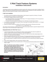
Header Installation
INSTALLATION
For the Header Frame, drill holes into wall through the existing holes in the Header Extrusion and attach to wall
using 1/2” through bolts or rods. Using 1/2” bolts or rods in all available holes is required (See Figures 10, 11, & 13).
Figure 10: Mounting detail - Insulated Panel Figure 11: Mounting detail - Block Wall
Warning when mounting Header assembly,
keep personnel out of the area below the
Header until it is secured to the wall. Failure
to do so could result in property damage,
bodily injury or death.
Figure 13: Mounting Header Assembly
Figure 12: Optional Heat Tape Connections (Freezer
Only)

ASI DOORS, INC. (800) 558-7068 asidoors.com
Panel Installation
INSTALLATION
Support Blocking
Bottom Panel Gaskets
1 Mount 2 roller trolley assemblies on rail on header.
Position approximately door width apart. Single roller
wheel on trolleys always goes to outside of panel. Make
sure jump rollers are installed & locktite is applied to
screw threads.
2 Move door panel into position in front of opening. Tilt
door panel up against opening, blocking up bottom of
panel on front side next to bottom gaskets with approx.
2” Blocks. Take care not to damage bottom gaskets.
3 Slide trolley assemblies into position so slotted holes in
trolley base plates align with mounting holes in top cor-
ners of door panel. Loosen trolley height locking bolts
& adjust trolley height adjustment bolt to lower/raise
trolley to meet top of door panel if needed.
4 Attach trolleys to door panel with panel mounting
bolts, and tighten bolts. Raise door slightly using height
adjustment bolts & remove blocking from bottom of
door.
5 Use trolley height adjustment bolts so bottom gaskets
on door panel completely seal against floor when door
is in the closed position.
6 Locate trolley cover plate & attach to both trolleys
using 2 screws per side.
Position Trolleys over
corners of Panel
Figure 22: Trolley and Panel Detail
Figure23: Position Panel Assembly
Figure 24: Panel Support Blocking
Warning when mounting Panel, keep personnel
out of the area below header and use caution
until the Panel is secured to the Header assembly.
Failure to properly install equipment could result in
property damage, bodily injury or death.
Note when tilting up Door Panel, use caution not to
damage bottom gaskets.
NOTE
Bottom Panel Gaskets
Support Blocking

ASI DOORS, INC. (800) 558-7068 asidoors.com
Panel Installation Continued
INSTALLATION
Header Rail
Door Panel
Jump Roller
Height Locking
Bolts
Height
Adjustment Bolts
Warning the use of Impact tools on adjustment
hardware is NOT recommended. Use of these tools
may damage the adjustment hardware,
compromising the ability to make door
adjustments.
1 Slide trolley assemblies into position so slotted holes
in trolley base plates align with mounting holes in top
corners of door panel. Loosen trolley height
locking bolts & adjust trolley height adjustment bolt
to lower/raise trolley to meet top of door panel if
needed.
2 Attach trolleys to door panel with panel mounting
bolts, and tighten bolts. Raise door slightly using
height adjustment bolts & remove blocking from
bottom of door.
3 Use trolley height adjustment bolts so bottom
gaskets on door panel completely seal against floor
when door is in the closed position.
4 Locate trolley cover plate & attach to both trolleys
using 2 screws per side.
Figure 26: Trolley and Panel Detail
Figure 27: Attach Trolley Cover Plate
Height
Adjustment Bolt
Height Locking
Bolts
Panel Mounting
Bolts
41A218 (ZN)
41A793 (SS)
Figure 25: Attach Trolleys to Panel

ASI DOORS, INC. (800) 558-7068 asidoors.com
Floor Hardware Installation
INSTALLATION
Floor Hardware Installation:
1 Locate lead edge roller and trailing edge roller in
loose parts box.
2 Place the lead edge roller on the floor in front of
the lead edge face frame, figure 28 (lead edge
roller wheel is larger in diameter that the trail
edge roller wheel).
3 Move door into the closed position.
4 Following the dimensions in figure 28, at the
door’s leading edge, place the lead edge roller on
the floor so that roller causes panel to be snug
against the gaskets. Drill holes in floor so that
bolts will be in the center of the two slotted bolt
guide holes. Attach using 3/8” anchor bolts.
5 Place the trail edge roller on the floor in front of
the trail edge face frame (Figure 29).
6 Move door into the open position.
7 Following the dimensions in figure 29, at the
door’s trailing edge, place the trail edge roller
on the floor so that as door closes, roller has
minimum contact with door panel. Drill holes in
floor so that bolts will be in the center of the two
slotted bolt guide holes. Attach using 3/8” anchor
bolts.
8 Move door into the closed position. Trail edge
roller should contact door wedge and cause panel
to be snug against the gaskets.
9 Manually move door to insure a tight seal.
Figure 28: Lead Edge Floor Roller
Figure30: Floor Rollers - Top View
Figure 29: Trail Edge Floor Roller

ASI DOORS, INC. (800) 558-7068 asidoors.com
Door Adjustment Location
INSTALLATION
Floor Hardware Installation:
Figure 31 illustrates the various adjustment points along the door to form a tight seal, yet not create seal wear. Visually
inspect seal to make sure no light is visible through the seals.
1 Sill gasket (trolley height) 1a & 1b (typ both panels) adjustment for leveling panel and adjusting distance from bottom
gasket to floor.
2 Belt tension adjustment for adjusting positioning accuracy during door open and close cycles (power doors only).
3 Floor roller adjustments for distance of panel gasket from LH face frame (3a. – LH floor roller) and distance of panel gasket
from RH face frame (3b. – RH floor roller).
4 Face frame covers adjustment for adjusting seal between vertical panel gaskets and face frames.
Figure 31: Door Adjustment Locations

ASI DOORS, INC. (800) 558-7068 asidoors.com
Door Adjustments Continued
INSTALLATION
Sill Gasket / Panel Height Adjustment:
1 Inspect sill (bottom) gasket position relative to the
floor. If gasket does not make contact with the floor
completely when closed, excessively drags on the
floor or the floor is uneven, adjustment of the sill
gasket is necessary.
2 Remove trolley cover plate by removing 2 screws
attaching it to trolley on both ends (Figure 32).
3 Adjust the sill gasket position by adjusting door
heights of the trolley assemblies on both ends of the
header rail assembly (Figure 33). Loosen 2 height
locking bolts on each trolley. Adjust height using
height adjustment bolt until bottom panel gasket
makes contact with floor. Re-tighten height locking
bolts. Make adjustment when door is closed.
4 Replace trolley cover plate.
Height Adjustment Bolt
Height Locking Bolts
Panel Mounting Bolts
41A218 (ZN)
41A793 (SS)
Figure 32: Remove Trolley Cover Plate
Warning the use of Impact tools on adjustment
hardware is NOT recommended. Use of these tools
may damage the adjustment hardware,
compromising the ability to make door
adjustments.
Figure 33: Adjust Trolley Height

ASI DOORS, INC. (800) 558-7068 asidoors.com
Idler Assembly
Belt Idler Adjustment Screw
Belt Idler Lock Nut
Door Adjustments Continued
INSTALLATION
Drive Belt Adjustment (Power doors only):
If door positioning during opening or closing cycles is erratic, drive belt may need tension adjustment or replacing.
1 Locate idler assembly on header ail assembly. On RH operator doors, will be on le side of header, near end of trolley
cover on LH side (Figure 34). For LH operator doors will be on RH side. Check belt tension. Belt should be reasonably tight
but deflect between 1/2” to 1” at center of belt with mild finger pressure. Visually inspect belt for wear and missing or dam-
aged teeth.
2 Loosen belt idler lock nut.
3 Use belt idler adjustment screw to tighten (or loosen) belt tension.
4 Re-tighten belt idler lock nut.
If belt is damaged and needs replacing, release all tension on belt, slip belt o of front side of idler pulley, and back side of
motor pulley on other end, replace belt, and re-tension as listed above.
Note doors with opening height under 7’ 6”, will
have a belt guard installed over idler pulley.
NOTE
Figure 34: Belt Tension Adjustment

ASI DOORS, INC. (800) 558-7068 asidoors.com
Door Adjustments Continued
INSTALLATION
Floor Roller Adjustments:
Inspect contact between vertical door gaskets and
face frames. If there are gaps, floor rollers may need
to be adjusted.
1 Loosen bolts holding floor rollers to floor.
2 Adjust position of floor rollers to insure vertical
door gaskets are making su icient contact with
face frames at the floor.
3 Re-tighten floor roller bolts.
Face Frame Cover Adjustments:
Inspect contact between vertical door gaskets and
face frames above floor to top of face frames. If there
are gaps above the floor, face frame cover position
may need to be adjusted. Face frame covers are
designed to slide out from face frame extrusions if
needed.
1 A er adjusting floor rollers to make contact with
vertical door gaskets at floor, check for gaps
between vertical door gaskets and surfaces of
face frame covers from floor to top of door
opening with door in closed position.
2 Manually pull face frame covers out to meet
surfaces of face frame covers at points where
there are gaps.
3 Lock face frame cover in place by driving #10 TEK
screws through face frame cover, into face frame
extrusion at these points. Use .75” Long screws or
shorter! Open door and add screws at the same
locations on other side to keep covers straight.
Face Frame Extrusion
Face Frame Cover
Adjust Face Frame
Cover position
#10 TEK Screws .75”
long maximum
Figure 35: Adjust Floor Roller Position
Figure 36: Adjust Face Frame Cover Position
Warning use .75” long screws or shorter for
securing position of Face Frame Covers. These
screws must not extend into pocket in Face Frame
where heat cables are held, or damage to heat
system may result.

ASI DOORS, INC. (800) 558-7068 asidoors.com
Wall Track Installation
INSTALLATION
1 Locate wall track, and detent bracket assemblies in shipping crate and loose parts box.
2 With doors in closed position, use following steps to mount wall track assemblies (Figure 37). Steps detail
mounting RH wall track assembly. For bi-part doors, there are mirrored assemblies on both sides of opening.
Mounting procedure is the same for both sides.
3 Mount detent bracket onto wall track bracket already mounted on door by asi. Hand tighten fasteners
(5/16-18 x .75 Carriage bolts and 5/16-18 whizlock nuts) so that detent bracket is approximately centered
vertically on slots in bracket (Figure 38).
4 Mount end of wall track assembly closest to door first (5/16” fasteners to mount wall track to wall are provided
by installer). Position end of wall track approximately 1/2” in from edge of trailing edge face frame, and lower
wall track assembly onto end of detent bracket, so that guide block on bracket fits into slot on the bottom of
wall track assembly (36.50” Dimension below is reference only and may vary depending on height adjustments
on door). Do not allow bracket to deflect downward severely. Adjust detent bracket in or out to fit guide block
securely into slot. Temporarily support other end in place so track is approximately 1/2” higher than end
closest to door (door slopes towards closed position). Add fasteners centered in end slots closest to door to
fasten this end, but do not fasten far end to wall until doing following steps.
5 While supporting other end of wall track assembly, slowly open door to full open position. Verify that guide
block is completely in slot at this end. Adjust height of wall track assembly at this end to fit guide block
securely into slot. Verify that panel return stud is inside of door return bracket. Adjust position of door return
bracket if needed. Use fasteners to fasten far end of wall track assembly to wall.
6 Manually move door to closed position and check that guide block is completely in slot for full length of door
travel. Add fasteners to all center slots to secure to wall.
7 Open & close door several times, checking that door moves freely, and that guide block rides in slot. Adjust
height of detent bracket, and vertical position of wall track assembly as needed (Figure 37 & 39). Tighten all
fasteners.
Figure 37: Wall Track Installation

ASI DOORS, INC. (800) 558-7068 asidoors.com
Wall Track Installation Continued
INSTALLATION
Figure 38: Wall Track Locator Assembly
Figure 39: Wall Track Locator Adjustments
Note views shown depict installation for a right
hand side wall Track. Installation of the le hand
side wall track is the same but mirrored to
opposite side.
NOTE
/