Page is loading ...

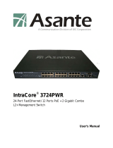
IntraCore
®
IC3624PWR
Layer 2+ Power over Ethernet (PoE) Switch
with Dual Gigabit
User’s Manual

2
IntraCore IC3624PWR Layer 2 PoE Switch with Dual Gigabit
IntraCore
®
IC3624PWR
Layer 2+ Power over Ethernet (PoE) Switch
with Dual Gigabit
User’s Manual
Asanté Technologies, Inc.
2223 Old Oakland Road
San Jose, CA 95131
USA
SALES
800-662-9686 Home/Office Solutions
800-303-9121 Enterprise Solutions
408-435-8388
TECHNICAL SUPPORT
801-566-8991: Worldwide
801-566-3787: Fax
www.asante.com/support
support@asante.com
[Default IP Address: 192.168.0.1]
[Default username: root ]
[Default password: Asante ]
Copyright © 2004 Asanté Technologies, Inc. All rights reserved. No part of this document, or any associated artwork,
product design, or design concept may be copied or reproduced in whole or in part by any means without the express
written consent of Asanté Technologies, Inc. Asanté and IntraCore are registered trademarks and the Asanté logo,
AsantéCare, Auto-Uplink, and IntraCare are trademarks of Asanté Technologies, Inc. All other brand names or
product names are trademarks or registered trademarks of their respective holders. All features and specifications
are subject to change without prior notice.
Rev. A 10/22/04

3
IntraCore IC3624PWR Layer 2 PoE Switch with Dual Gigabit
Table of Contents
Table of Contents...........................................................................................................................................................3
Chapter 1: Introduction...................................................................................................................................................7
1.1 Features...............................................................................................................................................................7
1.1.1 Connectivity ...................................................................................................................................................7
1.1.2 Performance ..................................................................................................................................................8
1.1.3 Management..................................................................................................................................................8
1.2 Network Management Options.............................................................................................................................8
1.3 Ports.....................................................................................................................................................................8
Chapter 2: Network Planning.........................................................................................................................................9
2.1 Management Access Overview............................................................................................................................9
2.2 SNMP Access ....................................................................................................................................................10
2.2.1 Protocols......................................................................................................................................................11
Chapter 3: Hardware Installation and Setup ................................................................................................................12
3.1 Installation Overview..........................................................................................................................................12
3.2 Safety Recommendations ..................................................................................................................................12
3.3 Site Requirements..............................................................................................................................................13
3.3.1 Environmental Requirements.......................................................................................................................13
3.3.2 Power...........................................................................................................................................................13
3.3.3 Cooling and Airflow......................................................................................................................................13
3.3.4 Rack Mounting.............................................................................................................................................13
3.4 Preparing for Installation.....................................................................................................................................14
3.5 Unpacking and Inspecting..................................................................................................................................14
3.5.1 Recommended Tools...................................................................................................................................15
3.6 Installing the Switch............................................................................................................................................15
3.6.1 Mounting the Switch in a Rack.....................................................................................................................15
3.6.2 Desktop or Shelf Mounting...........................................................................................................................16

4
IntraCore IC3624PWR Layer 2 PoE Switch with Dual Gigabit
3.7 Applying Power ..................................................................................................................................................16
3.8 Ethernet Cabling.................................................................................................................................................17
3.9 Connecting to the Console Port..........................................................................................................................17
3.9.1 Wiring Map for Serial Cable.........................................................................................................................18
Chapter 4: Connecting Network Devices .....................................................................................................................19
4.1 Twisted-Pair Devices..........................................................................................................................................19
4.1.1 Cable Guidelines..........................................................................................................................................19
4.1.2 Connecting to PCs, Servers, Hubs and Switches........................................................................................19
4.1.3 Network Wiring Connections........................................................................................................................20
4.2 Interpreting LEDs ...............................................................................................................................................20
4.3 Connectivity Guidelines......................................................................................................................................21
4.3.1 Fast Ethernet Ports......................................................................................................................................21
4.3.2 Combo Ports................................................................................................................................................21
4.4 Cable Labeling and Connection Records...........................................................................................................22
Chapter 5: Configuring the Switch ...............................................................................................................................23
5.1 Connecting to the Switch....................................................................................................................................23
5.2 Direct Access .....................................................................................................................................................24
5.3 Initial Logon........................................................................................................................................................26
Chapter 6: Using the Interface.....................................................................................................................................28
6.1 General Information Menu..................................................................................................................................28
6.2 Basic Configuration Menu ..................................................................................................................................30
6.2.1 Administration Configuration........................................................................................................................31
6.2.2 IP Configuration...........................................................................................................................................32
6.2.3 SNMP Configuration ....................................................................................................................................32
6.2.4 Port Configuration........................................................................................................................................37
6.2.6 Forwarding DB.............................................................................................................................................38
6.2.7 SNTP Configuration.....................................................................................................................................39
6.2.8 ARP Table....................................................................................................................................................40

5
IntraCore IC3624PWR Layer 2 PoE Switch with Dual Gigabit
6.3 Advanced Switch Configuration..........................................................................................................................41
6.3.1 VLAN Management......................................................................................................................................42
6.3.2 Link Aggregation..........................................................................................................................................45
6.3.3 Port Monitoring.............................................................................................................................................47
6.3.4 MSTP Configuration.....................................................................................................................................47
6.3.5 Access List Configuration.............................................................................................................................56
6.3.6 Quality of Service Configuration...................................................................................................................63
6.3.7 Storm Control...............................................................................................................................................64
6.3.8 802.1 Port Based Access Control................................................................................................................65
6.3.9 IGMP Snooping............................................................................................................................................66
6.3.10 Power over Ethernet..................................................................................................................................68
Map: Main Menu->Advanced Switch Configuration->Power over Ethernet ..........................................................68
6.4 Statistics.............................................................................................................................................................71
6.5 Tools ..................................................................................................................................................................72
6.5.1 TFTP Software Upgrade..............................................................................................................................72
6.5.2 Configuration File Upload/Download............................................................................................................73
6.5.3 System Reboot ............................................................................................................................................74
6.5.4 Ping Execution.............................................................................................................................................74
6.5.5 System Log..................................................................................................................................................75
6.6 Save Configuration.............................................................................................................................................76
6.7 Run CLI..............................................................................................................................................................76
Appendix A: Basic Troubleshooting .............................................................................................................................77
A.1 Diagnosing Switch Indicators.............................................................................................................................77
A.2 Power and Cooling Problems.............................................................................................................................77
A.3 Installation..........................................................................................................................................................77
A.4 In-Band Access..................................................................................................................................................77
Appendix B: Specifications...........................................................................................................................................79
Appendix C: Cables and Pin Assignments...................................................................................................................81
C.1 Twisted-Pair Cable and Pin Assignments..........................................................................................................81
C.1.1 Pin Assignments for 10BaseT/100BaseTX..................................................................................................81
C.1.2 Straight-Through Wiring..............................................................................................................................82
C.1.3 Crossover Wiring.........................................................................................................................................82

6
IntraCore IC3624PWR Layer 2 PoE Switch with Dual Gigabit
C.2 Pin Assignments for 1000BaseT Pin .................................................................................................................82
C.3 Cable Testing for Existing Category 5 Cable.....................................................................................................83
C.3.1 Adjusting Existing Category 5 Cabling to Run 1000BaseT..........................................................................83
C.4 Fiber Standards.................................................................................................................................................83
Appendix D: FCC Compliance and Warranty Statements............................................................................................85
D.1 FCC Compliance Statement..............................................................................................................................85
D.2 Important Safety Instructions.............................................................................................................................85
D.3 IntraCore Warranty Statement...........................................................................................................................86
Appendix E. Online Warranty Registration...................................................................................................................87

7
IntraCore IC3624PWR Layer 2 PoE Switch with Dual Gigabit
Chapter 1: Introduction
The IntraCore IC3624PWR Layer 2+ Power over Ethernet (PoE) with Dual Gigabit (IC3624PWR) is a product you can
use to build your next generation network.
The IC3624PWR device uses Layer 2+ technology and has 24 ports for 10/100/1000BastTX Fast Ethernet with 2
combination ports for added 10/100BaseT Gigabit Ethernet.
Use the advanced features on the IC3624PWR switch to deploy Voice over IP (VoIP) telephones, cameras and
wireless access points.
The following figure shows the front of the IC3624PWR PoE switch.
1.1 Features
The IntraCore IC3624PWR supports the following features:
1.1.1 Connectivity
Compared with conventional 24-port 10/100 Fast Ethernet Layer 2+ switches, the IC3624PWR delivers power for all
compatible devices.
• Meets IEEE 802.3af PoE standards
• 180 watts of total power (up to 15.4 watts per 10/100 port)
• IEEE 802.1p prioritization, DiffServ and IP ToS supports VoIP.
The switch supports all the services needed for your advanced network.
• Supports 802.1x authentication per port
• Up to 256 VLANs with GVRP and GARP
• 4 class of service queues per port
• IGMP v1 and v2 snooping support
• 6 groups of trunking for link aggregation and redundancy
• IEEE 802.1d and 802.1s spanning tree support with rapid reconfiguration and fast link option

8
IntraCore IC3624PWR Layer 2 PoE Switch with Dual Gigabit
1.1.2 Performance
The IC3624PWR switch uses a wire-speed, non-blocking switching fabric.
• Wire-speed Gigabit switching (1,488,000 pps) and Fast Ethernet switching (148,800 pps)
• Non-blocking 8.8 Gbps switch fabric
1.1.3 Management
• Web browser
• Telnet (multiple sessions)
• Console
• SNMP v1 and v2c
• RMON Groups 1, 2, 3 and 9
1.2 Network Management Options
The IntraCore IC3624PWR provides both local and remote management. You can configure or monitor the switch
using the embedded management software or by using SNMP applications. You can manage the switch by a direct
connection to the RS-232 console port (out-of-band), or a network connection (in-band) using Telnet, or the on-board
Web agent.
1.3 Ports
Each port has auto-negotiation, so the optimum transmission mode (half or full duplex), and data rate (10, 100, or
1000 Mbps) is always available. If a device connected to one of these ports does not support auto-negotiation, the
communication mode of that port can be manually configured.
Each port also supports auto-negotiation of flow control, so the switches can automatically prevent port buffers from
becoming saturated.

9
IntraCore IC3624PWR Layer 2 PoE Switch with Dual Gigabit
Chapter 2: Network Planning
This chapter gives an overview of switch management, including the methods you can use to manage your IntraCore
IC3624PWR Managed Switch. Topics include:
• Management Access Overview
• SNMP Access
• Protocols
2.1 Management Access Overview
You can access and manage the IC3624PWR Managed Switch using the following methods:
• Administration console
• Web browser interface
• External SNMP-based network-management application
The administration console and Web browser interface support are embedded in the switch’s firmware and available
for immediate use. Use the following table to determine which method is best suited for your network environment.

10
IntraCore IC3624PWR Layer 2 PoE Switch with Dual Gigabit
2.2 SNMP Access
You can use an external Simple Network Management Protocol (SNMP) based application to manage your
IC3624PWR switch.
This management method requires the SNMP agent on the switch and the SNMP Manager station to use the same
community string. Before using this method, enter the SNMP Manager station in the SNMP Host table on the switch.
This management method uses two community strings: the GET community string and the SET community string. If
the SNMP Manager only knows the SET community string, it can both read and write to the MIBs. If the SNMP
Manager only knows the GET community string, it only reads the MIB. The default GET community string for the
switch is public, and the host table is empty. The following figure is an example of this management method.
Management Method Advantages Disadvantages
Administration Console Out-of-band access through direct
cable connection eliminates network
bottlenecks, crashes, and downtime
No IP address or subnet is needed
Menu or CLI based
HyperTerminal access to full
functionality (standard Microsoft
Windows 95/98/NT/2000 operating
systems)
Must be near switch or use dial-up
connection
Not convenient for remote users
Not available using a GUI
Web Browser or Telnet Access from any location through the
switch’s IP address
Configure the switch remotely
Compatible with Internet Explorer
and Netscape Navigator Web
browsers
GUI data available
Menu or CLI interfaces available
Security can be compromised
Lag times on poor connections are
possible
GUI display may slow navigation
SNMP Agent Communicate at the Management
Information Base (MIB) level
Based on open standards
Requires SNMP manager software
Limited amount of information
available
Some settings require calculations
Security can be compromised
(hackers need only know the
community name)

11
IntraCore IC3624PWR Layer 2 PoE Switch with Dual Gigabit
2.2.1 Protocols
The IC3624PWR switch supports the following protocols:
• Virtual terminal protocols, such as Telnet
• SNMP
• Virtual Terminal Protocols
A virtual terminal protocol is a software program, such as Telnet, that allows you to establish a management session
from a Macintosh, a PC, or a UNIX workstation. Because Telnet runs over TCP/IP, you must have at least one IP
address configured on the IC3624 switch before you can establish a connection.
When using the terminal emulation method you must connect a terminal or PC directly to the console port. The
following figure shows a UNIX workstation connected to the system through a virtual terminal protocol (Telnet), and a
terminal connecting directly to the console port through a null-modem cable.
SNMP Protocol
SNMP is the standard management protocol for multi-vendor IP networks. SNMP supports transaction-based queries
that allow the protocol to format messages and to transmit information between reporting devices and data-collection
programs. SNMP runs on top of the User Datagram Protocol (UDP), offering a connectionless-mode service.

12
IntraCore IC3624PWR Layer 2 PoE Switch with Dual Gigabit
Chapter 3: Hardware Installation and Setup
This chapter describes the procedures for rack-mounting, connecting the cables, and powering up the IntraCore
IC3624PWR PoE switch at your site.
3.1 Installation Overview
1. Follow these steps to install the IntraCore IC3624PWR PoE switch:
2. Open the box and check the contents. For a complete list of the items included with the switch see “Equipment
Checklist” section later in this chapter.
3. Install the switch in an equipment or wall rack, or prepare for desktop placement.
4. Connect the power cord to the switch and to an appropriate power source.
5. Connect network devices to the switch.
See the sections below for more detailed installation instructions.
3.2 Safety Recommendations
The following information provides safety guidelines to ensure general safety and to protect the switch from damage.
Note:
The following guidelines may not include every possible hazard to which you may be exposed. Use caution
when installing this switch. Only trained and qualified personnel install or replace this equipment.
• Keep the switch clean
• Keep tools and components off the floor and away from foot traffic
• Do not wear rings or chains (or other jewelry). Metal objects can heat up and cause serious injury to persons and
damage to the equipment.
• Do not wear loose clothing. Fasten your tie or scarf and roll up your sleeves.
• When working with electricity, follow these guidelines:
• Disconnect all external cables before installing or removing the cover
• Do not work alone when working with electricity
• Always check that the cord has been disconnected from the outlet before performing hardware configuration
• Do not tamper with the equipment. Doing so could void the warranty
• Examine the work area for potential hazards (such as wet floors or ungrounded cables)

13
IntraCore IC3624PWR Layer 2 PoE Switch with Dual Gigabit
3.3 Site Requirements
Consider the following site requirements for proper installation.
3.3.1 Environmental Requirements
Choose a clean, dry, dust-free area location. Avoid direct sunlight, heat sources, or areas with high levels of
electromagnetic interference. Failure to observe these limits may cause damage to the switch and may void the
warranty.
3.3.2 Power
Make sure the power source adheres to the following guidelines:
Outlet: Properly grounded, located near the switch, and easily accessible
Power:
Auto Switching 100-240 VAC, 50/60 Hz, maximum 225 watts
Frequency range:
50/60 Hz
3.3.3 Cooling and Airflow
The IC3624PWR PoE switch use internal fans for air-cooling. Do not restrict airflow by covering or obstructing air
vents on the sides of the switch.
Operating Temperature: 32° to 104°F (0° to 40°C)
Relative Humidity: 10% to 90% non-condensing
3.3.4 Rack Mounting
Before mounting the switch in a rack follow these general precautions:
Size: 17.3 x 9.9 x 1.7 in (440 x 253 x 43 mm)
Weight: 9.5 lb (4.3 kg)
Temperature: The temperature within a rack assembly may be higher than the ambient room temperature check that
the rack-environment temperature is within the specified operating temperature range remains below 104°F (40°C).
Clearance:
Clear all obstructions, such as other equipment or cables, block airflow to or from the vents of the switch.
Be sure there is adequate clearance for servicing the switch.
Mechanical Loading: Do not place any equipment on top of a rack-mounted unit.
Circuit Overloading:
Be sure that the supply circuit to the rack assembly is not overloaded.
Grounding:
Rack-mounted equipment should be properly grounded. Particular attention should be given to supply
connections other than direct connections to the mains.

14
IntraCore IC3624PWR Layer 2 PoE Switch with Dual Gigabit
3.4 Preparing for Installation
Switches can be mounted in a standard 19-inch equipment rack or on a flat surface. Follow these general precautions
when planning your equipment locations and connections.
The site needs the following:
• Centrally located to the devices you want to link
• Near a power outlet.
• Constant temperature within 32° to 104°F (0° to 40°C) and its humidity within 10% to 90%, non-condensing
• Adequate space (approximately 2 in or 5 cm) on all sides for proper air flow
• Accessible for installing, cabling and maintaining the devices
• Clearly visible status LEDs
Additional precautions:
• Keep the front of the chassis free from obstruction and away from the exhaust air of other equipment. Electrical
equipment generates heat and the ambient room temperature be enough to cool the equipment to required
operating temperatures.
• Make sure twisted-pair cable is always routed away from power lines, fluorescent lighting fixtures and other
sources of electrical interference, for example radios and transmitters.
• Make sure that the unit is connected to a separate grounded power outlet that provides 100 to 240 VAC, 50 to 60
Hz, is within 8 ft (2.44 m) of each device and is powered from an independent circuit breaker. As with any
equipment, using a filter or surge suppressor is recommended.
3.5 Unpacking and Inspecting
Before you unpack your equipment examine all shipping containers for damage. If any damage has occurred, notify
the shipping carrier immediately. Unpack the unit by removing the packing material and lifting it from the protective
enclosures. Visually examine the equipment and check the container for parts and accessories. You should have the
following items:
• An IntraCore IC3624PWR PoE switch
• Four adhesive foot pads
• A Rack Mounting Kit
• Two brackets
• Four screws for attaching the brackets
• An AC Power Cord
• An RS-232 console cable
Contact your dealer immediately if any item is missing.

15
IntraCore IC3624PWR Layer 2 PoE Switch with Dual Gigabit
3.5.1 Recommended Tools
You need the following tools and equipment (not included) to install the switch into an equipment rack:
• Flat head screwdriver
• Phillips head screwdriver
• Four mounting screws for each device you plan to install in a rack (not included with the switch)
• Antistatic mat or foam
3.6 Installing the Switch
The switch can be mounted in a standard 19-inch equipment rack or place on a desktop or shelf. Mounting
instructions for each type of site follow.
3.6.1 Mounting the Switch in a Rack
When installing this unit in an empty rack, mount it at the bottom. When mounting this unit in a partially filled rack,
load the rack from the bottom to the top with the heaviest component at the bottom. Follow these steps to properly
install the switch into an equipment rack.
Caution: Before continuing, disconnect all cables from the switch.
To mount the switch onto an equipment rack:
• Place the switch on a flat, stable surface.
• Locate a rack-mounting bracket (supplied) and place it over the
mounting holes on one side of the switch.
• Use the screws (supplied) to secure the bracket (with a Phillips
screwdriver).
• Repeat the two previous steps on the other side of the switch.
• Place the switch in the equipment rack.
• Secure the switch attaching the mounting brackets onto the equipment rack with the screw supplied with the unit.

16
IntraCore IC3624PWR Layer 2 PoE Switch with Dual Gigabit
Warning:
Make sure you support the switch until all the mounting screws for each bracket is secured to the
equipment rack. Failure to do so could cause the switch to fall, which may result in personal injury or damage to the
switch.
When installing multiple switches, mount them in the rack, one below the other, in any order.
When installation is complete turn to the “Applying Power” section.
3.6.2 Desktop or Shelf Mounting
Follow these steps when planning to use the switch on either a desktop or a shelf:
1. Attach the four adhesive feet to the bottom of the switch.
2. Set the device on a flat surface near an AC power source, making sure there are at least two inches of space on
all sides for proper airflow.
3. Place each device squarely on top of the one below, in any order.
When installation is complete refer to the “Applying Power” section.
3.7 Applying Power
The system’s front panel LED display allows you to monitor the status of the switch. Follow these steps to connect
the switch.
1. Use the supplied power cord and plug the female end directly into the receptacle located at the back of the
device.
2. Plug the other end of the cord into a properly grounded electrical outlet.
3. Check the front-panel LEDs as the device is powered on to be sure the Power LED is lit. If not lit, check that the
power cable is correctly plugged in.
4. Connect the optional redundant power supply to the switch and to an AC power source by following the
instructions for the unit.
Warning: For International use: if you use power other than AC, you must use power cords that meet the appropriate
standards for the power you are using.

17
IntraCore IC3624PWR Layer 2 PoE Switch with Dual Gigabit
3.8 Ethernet Cabling
The cables you need are determined by the existing equipment.
To ensure proper operation when installing the switch into a network, make sure that the current cables are suitable
with either 10/100BaseTX, 10/100/1000BaseT or 1000BaseT operation. Check the following criteria against the
current installation of your network:
•
Cable type:
Unshielded twisted pair (UTP) or shielded twisted pair (STP) cables with RJ-45 connectors;
Category 3 or better for 10BaseT and Category 5 or better for 100BaseTX.
• Protection from radio frequency interference emissions
• Electrical surge suppression
• Separation of electrical wires (switch related or other) and electromagnetic fields from data based network wiring
• Safe connections with no damaged cables, connectors, or shields
RJ-45 Connector
When attaching a workstation to the switch, a standard straight-through CAT5 cable may be used.
3.9 Connecting to the Console Port
The DB-9 serial port located on the front panel is used to connect to the switch for out-of-band console configuration.
The on-board configuration program can be accessed from a terminal or a PC running a terminal emulation program.
The pin assignments used to connect to the serial port are provided in the following tables.

18
IntraCore IC3624PWR Layer 2 PoE Switch with Dual Gigabit
3.9.1 Wiring Map for Serial Cable
The following table describes the serial cable wiring information.
Switch’s 9-Pin Serial Port Null Modem PC’s 9-Pin DTE Port
2 RXD (receive data) ! 3 TXD (transmit data)
3 TXD " 2 RXD (receive data)
5 SGND (signal ground) --- 5 SGND (signal ground)
The serial port configuration requirements are as follows:
• Default Baud rate—9,600 bps
• Character Size—8 Characters
• Parity—None
• Stop bit—One
• Data bits—8

19
IntraCore IC3624PWR Layer 2 PoE Switch with Dual Gigabit
Chapter 4: Connecting Network Devices
The switch is designed to interconnect multiple segments (or collision domains). It can be connected to network cards
in PCs and servers, and to hubs, routers, or other switches.
4.1 Twisted-Pair Devices
Each device requires an unshielded twisted-pair (UTP) cable with RJ-45 connectors at both ends. Use Category 5 for
100BaseTX connections, and Category 3, 4 or 5 for 10BaseT connections.
4.1.1 Cable Guidelines
The RJ-45 ports on these switches support automatic MDI/MDI-X pinout configuration, so you can use standard
straight-through twisted-pair cables to connect to any other network device (PCs, servers, switches, routers, or hubs).
Caution:
Do not plug a phone jack connector into an RJ-45 port. Doing this will damage the switch. Use only
twisted-pair cables with RJ-45 connectors that conform to FCC standards.
4.1.2 Connecting to PCs, Servers, Hubs and Switches
Attach one end of a twisted-pair cable segment to the device’s RJ-45 connector.
If the device is a PC card and the switch is in the wiring closet, attach the other end of the cable segment to a
modular wall outlet that is connected to the wiring closet. (See “Network Wiring Connections” later in this chapter.)
Otherwise, attach the other end to an available port on the switch.
Make sure each twisted pair cable does not exceed 100 meters (328 ft) in length.
As each connection is made, the Link LED (on the switch) corresponding to each port lights up to indicate that the
connection is complete. (For more LED information see, “Interpreting LEDs” later in this chapter.)

20
IntraCore IC3624PWR Layer 2 PoE Switch with Dual Gigabit
4.1.3 Network Wiring Connections
The punch-down block is an integral part of many of the newer equipment racks. It is actually part of the patch panel.
Instructions for making connections in the wiring closet with this type of equipment follows.
Attach one end of a patch cable to an available port on the switch, and the other end to the patch panel.
Attach one end of a cable segment to the back of the patch panel where the punch-down block is located, and the
other end to a modular wall outlet.
Label the cables to simplify future troubleshooting.
Equipment Rack
(side view)
Network Switch
Patch Panel
Punch-Down Block
Wall
wit ch 10 /10 0
6724 L 3
E
S
4
5
2
4
C
4.2 Interpreting LEDs
The LEDs are located on the front panel.
/
