Page is loading ...

IntraCore 8000
Ethernet Switch
User’s Manual
August 2000
Part Number 06-00566-00

Copyright Notice
All rights reserved. No part of this manual, or any associated artwork, software, product, design or
design concept, may be copied, reproduced or stored, in whole or in part, in any form or by any means
mechanical, electronic, optical, photocopying, recording or any other wise, including translation to
another language or format, without the express written consent of Asanté Technologies, Inc.
Trademarks
Asanté Technologies and IntraCore are trademarks of Asanté Technologies, Inc. Ethernet is a registered
trademark of the Xerox Corporation. All brand names and products are trademarks or registered trade-
marks of their respective holders.
FCC Information
This device complies with part 15 of the FCC Rules. Operation is subject to the following two condi-
tions: (1) this device may not cause harmful interference and (2) this device must accept any interfer-
ence received, including interference that may cause undesired operation.
Operation of this equipment in a residential area is likely to cause interference, in which case, the user,
at his or her own risk and expense, will be required to correct the interference.
LIMITED FIVE YEAR WARRANTY
Subject to the limitations and exclusions below, Asanté warrants to the original end user purchaser that
the covered products will be free from defects in title, materials and manufacturing workmanship for a
period of five years from the date of purchase. This warranty excludes fans, power supplies, non-inte-
grated software and accessories. Asanté warrants that the fans and power supplies will be free from
defects in title, materials and manufacturing workmanship for one year from date of purchase. Asanté
warrants that non-integrated software included with its products will be free from defects in title, mate-
rials, and workmanship for a period of 90 days from date of purchase, and the Company will support
such software for the purpose for which it was intended for a period of 90 days from the date of pur-
chase. This warranty expressly excludes problems arising due to compatibility with other vendors
products, or future compatibility due to third party software or driver updates.
To take advantage of this warranty, you must contact Asanté for a return materials authorization (RMA)
number. The RMA number must be clearly written on the outside of the returned package. Product
must be sent to Asanté postage paid. In the event of a defect, Asanté will repair or replace defective
product or components with new, refurbished or equivalent product or components as deemed appro-
priate by Asanté. The foregoing is your sole remedy, and Asanté's only obligation, with respect to any
defect or non-conformity. Asanté makes no warranty with respect to accessories (including but not lim-
ited to cables, brackets and fasteners) included with the covered product, nor to any discontinued prod-
uct, i.e., product purchased more than thirty days after Asanté has removed such product from its price
list or discontinued shipments of such product.
This warranty is exclusive and is limited to the original end user purchaser only. This warranty shall not
apply to secondhand products or to products that have been subjected to abuse, misuse, abnormal elec-
trical or environmental conditions, or any condition other than what can be considered normal use.
ASANTÉ MAKES NO OTHER WARRANTIES, EXPRESS, IMPLIED OR OTHERWISE, REGARDING THE
ASANTÉ PRODUCTS, EXCEPT TO THE EXTENT PROHIBITED BY APPLICABLE LAW, ALL WARRANTIES
OR CONDITIONS OF MERCHANTABILITY OR FITNESS FOR A PARTICULAR PURPOSE ARE HEREBY DIS-
CLAIMED. ASANTÉ’S LIABILITY ARISING FROM OR RELATING TO THE PURCHASE, USE OR INABILITY
TO USE THE PRODUCTS IS LIMITED TO A REFUND OF THE PURCHASE PRICE PAID. IN NO EVENT WILL
ASANTÉ BE LIABLE FOR INDIRECT, SPECIAL, INCIDENTAL, OR CONSEQUENTIAL DAMAGES FOR THE
BREACH OF ANY EXPRESS OR IMPLIED WARRANTY, INCLUDING ECONOMIC LOSS, DAMAGE TO PROP-
ERTY AND, TO THE EXTENT PERMITTED BY LAW, DAMAGES FOR PERSONAL INJURY, HOWEVER
CAUSED AND ON ANY THEORY OF LIABILITY (INCLUDING NEGLIGENCE). THESE LIMITATIONS SHALL
APPLY EVEN IF ASANTE HAS BEEN ADVISED OF THE POSSIBILITY OF SUCH DAMAGES OR IF THIS
WARRANTY IS FOUND TO FAIL OF ITS ESSENTIAL PURPOSE.
Some jurisdictions do not allow the exclusion or limitation of incidental or consequential damages or
limitations on how long an implied warranty lasts, so the above limitations or exclusions may not apply
to you. This warranty gives you specific legal rights, and you may have other rights, which vary from
jurisdiction to jurisdiction.

Page i
Table of Contents
Introduction .................................................................................. 1-1
IntraCore Architecture Overview .................................................1-1
The Core Switching Engine ..................................................... 1-1
Infrastructure Connectivity .......................................................1-2
Network Management, Security, Performance, and Control ...1-2
The IntraCore Product Family ..................................................... 1-3
The IntraCore 8000 .....................................................................1-5
Expansion Modules ....................................................................1-5
8-port 10/100 Switch Module ................................................... 1-5
Gigabit Ethernet Switch Module ..............................................1-6
Features ...................................................................................... 1-7
Defaults and Specifications ........................................................1-9
LEDs .........................................................................................1-10
Installation and Setup ..................................................................2-1
Installation Guidelines .................................................................2-1
Power Requirements ...............................................................2-1
Environmental Requirements ..................................................2-1
Cooling and Airflow .................................................................. 2-1
Installation Overview ................................................................... 2-2
Chassis Installation/Placement ...................................................2-3
Installation in an Equipment Rack ...........................................2-3
Free-Standing/Desktop Placement ..........................................2-4
Stacking Switches ....................................................................... 2-5
Installing Port Expansion Modules ..............................................2-7
Installing GBIC Interfaces ........................................................2-8
Connecting Power ......................................................................2-9
Connecting to the Network ....................................................... 2-10
10/100BaseX Ports Cabling Procedures ...............................2-10
1000BaseX Ports Cabling Procedures ..................................2-11
Configuring for Management ....................................................2-11
BootP Configuration ..............................................................2-11
Connecting To a Console ...................................................... 2-12

Page ii
Management Options ............................................................... 2-13
Out-of-Band Management .................................................... 2-13
In-Band Management ........................................................... 2-14
Configuration ............................................................................... 3-1
Local Management Interface ...................................................... 3-2
Logging In ............................................................................... 3-2
Main Menu .............................................................................. 3-3
Viewing General Information ...................................................... 3-4
Configuration Menu .................................................................... 3-6
System Administration Configuration ......................................... 3-8
Current Settings ...................................................................... 3-8
Changing System Administration Info ..................................... 3-8
System IP Configuration ............................................................. 3-9
Current Settings .................................................................... 3-10
Changing System IP Information .......................................... 3-10
Bootstrap Configuration ............................................................ 3-11
Loading Software Locally ...................................................... 3-12
Loading Software Remotely .................................................. 3-13
SNMP Configuration ................................................................. 3-16
Current Settings .................................................................... 3-17
Changing Community Strings ............................................... 3-17
Enabling Authentication Traps .............................................. 3-18
Adding or Updating a Trap Receiver ..................................... 3-18
Deleting a Trap Receiver ...................................................... 3-19
Port Configuration .................................................................... 3-19
Viewing Legends for Configuration Settings ......................... 3-21
Current Port Settings ............................................................ 3-22
Enabling or Disabling a Port ................................................. 3-22
Configuring Auto-Negotiation ................................................ 3-23
Configuring a Port Manually .................................................. 3-24
Configuring 1000BaseX Ports ............................................... 3-25
Advanced Port Configuration ................................................... 3-27
Current Settings .................................................................... 3-29
Setting the Maximum Broadcast or Multicast Rate ............... 3-29
Enabling or Disabling 802.3x Flow Control ........................... 3-30
Setting Port Default Priority ................................................... 3-31
Global Port Configuration ......................................................... 3-31

Page iii
Unicast Forwarding Database Configuration ............................ 3-33
Current Settings ..................................................................... 3-34
Displaying the Forwarding Database .....................................3-34
Searching for a MAC Address ...............................................3-36
Setting the MAC Address Age-Out Time ............................... 3-37
Image File Downloading Configuration .....................................3-38
Image Downloading Through TFTP ...................................... 3-39
Serial Downloading Configuration ......................................... 3-42
System Reset Configuration ..................................................... 3-45
Current Options .....................................................................3-46
Resetting the IntraCore 8000 ................................................ 3-46
Scheduling a System Reset .................................................. 3-47
Viewing the System Log ........................................................... 3-47
Clearing the System Log .......................................................3-48
User Interface Configuration .....................................................3-49
Current Settings ..................................................................... 3-49
Setting Console Idle Time-out Period .................................... 3-51
Setting Telnet Idle Time-out Period .......................................3-51
Changing the Password ........................................................ 3-51
Enabling or Disabling the Web Server ...................................3-52
Viewing Statistics ...................................................................... 3-52
Advanced Management ............................................................... 4-1
Spanning Tree Protocol .............................................................. 4-1
Overview .................................................................................. 4-1
How It Works ...........................................................................4-2
Enabling and Disabling STP .................................................... 4-2
Configuring Spanning Tree Parameters .................................. 4-3
Current STP Settings ...............................................................4-5
Spanning Tree Port Configuration ...........................................4-6
Setting Port Priority and Path Cost ..........................................4-6
SNMP and RMON Management ................................................ 4-7
RMON Management ................................................................ 4-8
Security Management .................................................................4-9
Current Settings ..................................................................... 4-10
Duplicated IP Detection and Trap ..........................................4-11
Enabling and Disabling Station Movement Trap ................... 4-12
Configuring Port Security .......................................................4-13
Configuring Port New Node Detection Trap ..........................4-14

Page iv
Configuring Port Lock and Intruder Lock .............................. 4-15
Setting the Intruder Trap ....................................................... 4-17
Inserting/Modifying a Port Trusted MAC Address ................. 4-17
Resetting Security to Defaults ............................................... 4-17
VLAN Management .................................................................. 4-18
VLAN Specifications for the IntraCore 8000 ......................... 4-18
Other VLAN Features in IntraCore 8000 ............................... 4-19
Overview of VLANs ............................................................... 4-19
VLAN Groups ........................................................................ 4-21
Independent vs. Shared Learning ......................................... 4-22
Inter-Switch Links .................................................................. 4-23
Configuring VLAN Management ........................................... 4-26
Configuring Static VLAN Groups .......................................... 4-27
Advanced Static VLAN Configuration ................................... 4-30
Configuring VLAN Port Attributes ......................................... 4-33
Configuring Inter-Switch Links .............................................. 4-36
Displaying a Summary of VLAN Groups ............................... 4-38
Displaying a VLAN Port Summary ........................................ 4-38
Displaying a VLAN FID-VID Association Summary .............. 4-39
Resetting VLAN Configuration to Defaults ............................ 4-39
Configuring GVRP ................................................................ 4-39
Multicast Traffic Management .................................................. 4-44
Configuring Multicast Traffic Management ........................... 4-46
Current Settings .................................................................... 4-47
Multicast Forwarding Database Configuration ...................... 4-48
Web Browser Management ......................................................... 5-1
Accessing with a Web Browser .................................................. 5-1
Management Buttons ................................................................. 5-3
Front Panel Button ..................................................................... 5-3
Genl Info (General Information) Button ...................................... 5-5
Statistics Button .......................................................................... 5-6
Port Config (Port Configuration) Button .................................... 5-10
Span Tree (Spanning Tree) Button .......................................... 5-11
SNMP Button ............................................................................ 5-12
Addr (Address) Table Button .................................................... 5-13

Page v
VLAN Button .............................................................................5-14
Port Configuration ..................................................................5-14
VLAN Configuration .............................................................. 5-15
Duplicate IP Button ................................................................... 5-19
Technical Support ....................................................................... A-1
Contacting Technical Support .................................................... A-1
MIB Statistics .............................................................................. B-1
MIB Object Definitions for Counters .......................................... B-1
Readable Frames ................................................................... B-1
Readable Octets ..................................................................... B-1
FCS Errors .............................................................................. B-1
Alignment Errors ..................................................................... B-2
Frame Too Longs ................................................................... B-2
Short Events ........................................................................... B-2
Runts ...................................................................................... B-3
Collisions ................................................................................ B-3
Late Events ............................................................................. B-4

Page vi

Page 1-1
1
Introduction
This chapter introduces the IntraCore architecture, then gives a description
of the chassis and the various modules that can be installed in the IntraCore
8000. There are also tables of the key features, default settings, and
specifications of the IntraCore 8000, and explanations of the different LED
indicators used by the various modules.
IntraCore Architecture Overview
Asanté has developed the IntraCore™ Architecture to meet the needs of
multi-service networks that support all applications and data types. The
architecture is standards-based and provides
G multi-vendor inter-operability
G a migration path from current systems
G investment protection
With the IntraCore Architecture, Asanté has found innovative ways of
embracing industry standards and technology advances to create products
capable of meeting real world requirements for converged, multi-service
networks.
The overall design incorporates a family of tightly integrated ASICs,
designed as system building blocks. These building blocks enable the rapid
development of advanced networking systems that are timed to meet market
requirements. The architecture ensures consistent high performance as
systems scale their capacity and feature capability. This approach extends
the useful life of the system and protects customer investments.
The Core Switching Engine
The Core Switching Engine is the centerpiece for all IntraCore products.
Based on advanced silicon ASICs, the Core Switching Engine is a high
performance, non-blocking, multi-gigabit switching fabric with scalable
bandwidth capacity. The Core Switching Engine is data format independent
and can support either frame or cell based interfaces. This capability is
becoming increasingly important as enterprise (primarily frame-based) and
service provider (primarily cell-based) networks move closer together.

Introduction
Page 1-2
Infrastructure Connectivity
The second key element of the architecture is Infrastructure Connectivity.
IntraCore specifies standards based, high performance, cost effective
technologies for connectivity among devices in the network.
In the LAN –
At the network edge, Layer 2 switched 10/100/1000 Ethernet meets the
requirements for high-speed connectivity of desktop computers and scalable,
cost effective data transmission for trunks to the network core.
In the network core, Layer 2/3+-switched 10/100/1000 Ethernet meets the
requirements for high speed, scalable, cost effective data transmission and
support for all multi-service data types. High performance servers can be
centrally located for added physical security.
Throughout the LAN, advanced queuing techniques combined with multiple
priority levels and support for industry standard 802.1Q and 802.1p enable
Quality of Service within the network.
In the MAN/WAN –
Long haul Gigabit Ethernet, ATM, and Packet over SONET meet the
requirements for all of the following:
G scalable, cost effective data transmission
G support for all multi-service data types
G service provider inter operability
Network Management, Security, Performance, and
Control
IntraCore includes a rich suite of features required for the effective
management, security, performance, and control of the network. The
following table illustrates the features and standards supported by the
IntraCore architecture.

The IntraCore Product Family
Page 1-3
Table 1-1 Summary of IntraCore’s supported features
The IntraCore Product Family
The Asanté IntraCore architecture is the basis for a family of switching
system products in fixed, stackable and chassis form factors that allow
customers to integrate telephony, video and data applications. Initially, two
systems are offered that provide high performance, high port-count, Layer 2
switching. Additional configurations will be introduced to offer advanced
Layer 3 and above routing, traffic classification, advanced QoS, higher
bandwidth and port capacity. All systems will be consistent in their
Feature
Manage-
ment
Security
Perfor-
mance
Control
Web Browser Management Supported
SNMP, RMON Supported Supported Supported
Standard MIsS Supported Supported Supported
802.1P Priority Supported Supported
802.1Q VLAN Tagging Supported Supported Supported
802.1D – Spanning Tree Supported Supported Supported
IGMP V1, V2 Snooping Supported Supported
RSVP Snooping Supported Supported
GARP Multicast Registration Supported Supported
Duplicate IP addr. detection Supported Supported
Station movement notification Supported Supported
IP to MAC address binding Supported Supported
Controlled management access Supported
GVRP (Group VLAN Regis-
tration Protocol)
Supported Supported Supported
Advanced Port Configuration:
Broadcast & Multicast rate
limit & port priority
Supported Supported Supported

Introduction
Page 1-4
operation and management allowing customers to seamlessly deploy any
model in their network.
Edge Switches
Edge Switches provide the first point of connectivity to the network.
Connecting to an Enterprise Switch in the network core, Edge Switches
provide aggregation of traffic from desktop computers over high capacity
trunks. The initial product introduced in the Edge Switch category is the
IntraCore 8000.
The IntraCore 8000 is a stackable, high performance solution for enterprise
edge applications. Each stack supports up to 192 10/100Mbps switched
Ethernet connections for cost-effective high-density connectivity in wiring
closets. The system can operate as a stand-alone network or be used in
combination with IntraCore 8000 in the backbone.
Enterprise Switches
In the network core, Enterprise Switches are deployed to aggregate traffic
from wiring closets and provide high-speed connectivity to network servers.
Typically these switches are modular in form factor, and can be easily
upgraded or reconfigured. This flexibility provides for customized
configurations to meet a wide variety of requirements. The initial product
introduced in this category is the IntraCore 9000.

The IntraCore 8000
Page 1-5
The IntraCore 8000
The IntraCore 8000 is a stackable, high performance solution for enterprise
edge applications. Each stack supports up to 192 10/100Mbps switched
Ethernet connections for cost-effective high-density connectivity in wiring
closets. The system can operate as a stand-alone network or be used in
combination with an IntraCore 8000 in the backbone.
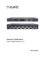
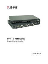
Figure 1-1 IntraCore 8000 Front Panel
Expansion Modules
The following modules can be used to extend the capabilities of the
IntraCore 8000.
8-port 10/100 Switch Module
This module provides 8 ports supporting switched 100BaseTX or 10BaseT
per port. Each module occupies a single slot and has either 24 RJ-45
connectors or 2 RJ-21 connectors.
Figure 1-2 8-port 10/100 Switch Module

Introduction
Page 1-6
Gigabit Ethernet Switch Module
This module provides a slot for a switched Gigabit Ethernet port. Each
module occupies a single slot and has a GBIC port that accepts Asanté or
third party GBIC interfaces. The following subsections describe the possible
GBIC interfaces.
Figure 1-3 Gigabit Ethernet Switch Module
1000Base SX GBIC
This module provides a GBIC interface with SC-type fiber connectors. The
interface supports 62.5 and 50 micron multimode fiber media. The 62.5
micron multimode fiber can be up to 275 meters long, and the 50 micron
multimode fiber can be up to 550 meters long.
1000BaseLX Long Haul GBIC
This module provides a GBIC interface for SC-type fiber connectors. The
interface supports 10 micron single mode fiber for distances up to 100
kilometers.
1000BaseLX GBIC
This module provides a GBIC interface for SC-type fiber connectors. The
interface supports 10 micron single mode fiber for distances up to 5
kilometers.

Features
Page 1-7
Features
The following table lists the major features of the IntraCore 8000 switch.
Feature Description
Media Flexibility Expansion module options include 8-port 10/100 Base-TX
switched Ethernet modules and single-port Gigabit Ethernet
modules with GBIC slots.
High Density Supports up to 192 10/100 switched Ethernet ports or up to 3
switched Gigabit Ethernet ports and 24 10/100 switched Ether-
net ports in a single stacking unit. This saves space in crowded
equipment rooms.
ASIC-Based Architec-
ture
ASIC-based packet processing provides wire speed perfor-
mance on all interfaces.
High Performance
16Gbps Backplane
The system supports current requirements for multi-service
voice, video, and data applications with bandwidth to spare.
The high-capacity backplane is designed so that it may be
scaled up to 80 Gbps, extending the useful life of the chassis.
Multiple Priority
Queues
The “application aware” system ensures that mission critical
applications get the bandwidth and priority they need, even
under heavy traffic conditions. When network congestion
occurs, low latency requirements are managed by the system.
Stackable Form Factor
with modular expan-
sion options
Each stack unit supports three option slots that can be custom-
ized to meet customer configuration requirements. Unique
stacking design delivers scalable system bandwidth assuring
maximum system performance regardless of configuration.
Configuration Flexibil-
ity and Growth
Expansion modules can be mixed and matched in any configu-
ration and quantity to meet design requirements. You can add
capacity whenever your business requires it.
GBIC Modules for
Gigabit Ethernet Media
Flexibility
The two GBIC Gigabit Ethernet modules can be configured
with any combination of 1000SX, 1000LX or 1000LX (Long
Haul) GBIC interfaces. Either Asanté or third party GBIC inter-
faces can be used, and the interfaces can be “hot swapped.”
This means that GBIC interfaces can be re-deployed based on
the user’s applications.
Installation Options The system can be rack-mounted to save space.

Introduction
Page 1-8
Table 1-2 IntraCore 8000 Features
Security Node summary tracks MAC and IP addresses per device, for
multiple devices on each port. The Port Security feature pro-
vides per-port security, allowing the network manager to spec-
ify which MAC is authorized on each port. Only the device with
that MAC address is allowed to connect to that specific port.
Web Based Manage-
ment
Built-in Web-based interface is provided for chassis manage-
ment, module management, port-level control, and monitoring.
The IntraCore 8000 can also be managed via Telnet, Console,
or third party SNMP console.
VLANs Supports up to 64 port-based VLANs (IEEE 802.1Q compliant)
for security, logical network design, and the control of broad-
cast traffic. The 802.1Q standard specifies VLAN tagging for
trunking VLANs from switch to switch, or switch to router.
Compatible with all 802.1Q equipment for easy integration into
existing networks.
Multicast Control The IntraCore 8000 supports standards based IGMP snooping
and GMRP for control of multicast traffic generated by band-
width-hungry applications such as video, ensuring maximum
application and network performance.
RMON The administrator can use an RMON probe for in-depth traffic
analysis, with support for four groups of RMON.
Spanning Tree Protocol Spanning Tree Protocol (STP) detects and eliminates data loops
to prevent broadcast storms from overwhelming your network.
Y2K compliance All IntraCore 8000 modules are Y2K compliant.
Feature (Cont.) Description (Cont.)

Defaults and Specifications
Page 1-9
Defaults and Specifications
The IntraCore 8000 is shipped with the following factory default settings
and specifications:
Table 1-3 Defaults and Specifications
Configuration Default Setting
Backplane Speed 16Gbps/stack unit, up to 80Gbps in a 4 unit stack.
Switching Method Store-and-forward
Forwarding Rates:
(64 byte packets)
Switched 10Mbps = 14,880 pps
Switched 100Mbps = 148,810 pps
Switched 1000Mbps = 1,488,100 pps
Buffer Size 4MB
MAC Address Table 8K
Full-Duplex Standards based Auto-negotiation enabled
VLAN 64 port-based VLANs, GVRP support, 802.1Q VLAN Tagging
Spanning Tree Protocol 802.1D, enabled
Flood Rate Limiting Broadcast/multicast traffic
Priority 802.1p, 8 levels mapped to 4 queues
RMON Groups 1-3, 9
SNMP MIB-II, Bridge MIB, RMON MIB, Asanté private MIBs
Console Baud Rate 9600
Password Asante

Introduction
Page 1-10
LEDs
The following indicator lights are used on the various modules of the
IntraCore 8000.
Table 1-4 LEDs and their meanings
Figure 1-4 LEDs on face plate
LED Color and Meaning
Stacking (to left of modules)
Power Green - Power is on when lit
Stack Number Specifies IntraCore 8000 Unit – #1 is bottom unit
Stack CPU Specifies IntraCore 8000 unit with management CPU
Matrix Board Present Indicates whether or not current unit has the Matrix
module for the other units in the stack
MII Present Indicates whether or not a Media Independent Interface
module has been installed in the current IntraCore 8000
unit
8-port 10/100 Switch Module
Link/Speed Green - Connection and link have been made
Duplex/Activity Green -Full Duplex
Amber - Half Duplex Blinking - Active
Gigabit Switch Module
Power Green - Power is on when lit
Link Green - Connection and link have been made.

Page 2-1
2
Installation and Setup
This chapter explains how to install, connect, and configure the IntraCore
8000 chassis and modules to work with your network. It also explains how
to set up your IntraCore 8000 for management, either from a console, via
telnet, via SNMP, or by using a Web browser.
Installation Guidelines
The following guidelines will help you prepare to install your IntraCore
8000 in such a way that it has the proper power supply and environment.
Power Requirements
The source electrical outlet should be installed near the IntraCore 8000 and
easily accessible. It must also be properly grounded.
Make sure the power source adheres to the following guidelines:
G Voltage range: 100 to 240 VAC
G Frequency range: 60/50 Hz
G Maximum current: 3.5 A per power supply at 110 volts
Environmental Requirements
The IntraCore 8000 must be installed in a clean, dry, dust-free area with
adequate air circulation to maintain the following environmental limits:
G Temperature: 0° to 40° C (32° to 104° F)104°
G Relative Humidity: 5% to 85% non-condensing
Avoid direct sunlight, heat sources, or areas with high levels of
electromagnetic interference.
Cooling and Airflow
Do not restrict air flow by covering or obstructing air vents on the sides of
the IntraCore 8000.

Installation and Setup
Page 2-2
Installation Overview
The table below describes the steps needed to install the IntraCore 8000. The
steps that are optional are labeled “optional” and the steps that are required
are labeled “required.” The sections that follow explain each step in detail.
Table 2-1 Installation Overview
Step Action to Be Taken
1 (Required)
Open the box and check the contents. See the Package Contents sheet
for a complete list of the items included with your IntraCore 8000.
2 (Required)
Install the IntraCore 8000 chassis in an equipment rack or wall rack,
or prepare it for desktop placement. See page 2-3.
3 (Optional)
Create a stack of up to four IntraCore 8000 switches. See page 2-5.
4 (Optional)
Install the port expansion modules you have purchased for your Intra-
Core 8000 and ensure each is properly seated and locked in place.
See page 2-7.
5 (Required)
Connect the power supply. See page 2-9.
6 (Required)
Connect network devices to the IntraCore 8000. See page 2-10.
7 (Required)
Configure the IntraCore 8000 for management capabilities.
See page 2-11.
/
