Page is loading ...

MO-453
ECN 4809-MA MADE IN USA
ECM OPERATION MANUAL
Model:
CSHB60-90XE
c WARNING:
• Do NOT store or use gasoline or other flammable vapors and liquids
in the vicinity of this or any other appliance.
• Improper installation, adjustment, alteration, service, or
maintenance can cause a fire or explosion resulting in property
damage, personal injury, or loss of life. For assistance or additional
information consult a qualified installer or service agency.
These instructions should be:
• read prior to installing the furnace
• retained for reference by qualified service personnel
• reviewed before performing any service or maintenance
Crown Boiler Company
3633 “I” Street
Philadelphia, Pennsylvania 19134

All installations and services must be performed by qualified service personnel.
i
INDEX
SECTION
BEGINNING PAGE
I. BLOWER CONTROLLER INFORMATION 1
A. TERMINAL DEFINITIONS & FIELD WIRING 1
B. WIRING & SWITCHES 2
C. INPUTS 3
D. OUTPUTS 4
E. OPERATING MODES 4
F. CFM TABLES 6
II. ECM TROUBLESHOOTING 7
A. DIAGNOSTIC FEATURES 7
B. GENERAL GUIDELINES TO TROUBLESHOOTING GE ECM 7
C. TROUBLESHOOTING CHARTS 10

All installations and services must be performed by qualified service personnel.
1
I. BLOWER CONTROLLER INFORMATION
A. TERMINAL DEFINITIONS & FIELD WIRING
Burner Harness Connector P1
Pin 1 – Limit switch connection.
Pin 2 – 120 VAC Line connection.
Pin 3 – Burner pilot contact.
Pin 4&5 – 120 VAC Neutral connection.
Pin 6 – Burner pilot contact.
Pin 7&8 – From oil primary control.
Pin 9 – Limit Switch Input (LSI).
Field Wiring to Burner
Pilot (Tstat) Neutral Line
Yellow Wires
White Red
T-T terminals
White Black
T-stat terminals
White Black
Harness Wires
Beckett Connections
Riello Connections
Carlin Connections
T-T terminals
White Black
Thermostat/Humidistat connections
"C" Common/ground
"W" Thermostat call for heat
"R" 24 VAC to thermostat
"G" Thermostat call for fan
"Y" Thermostat call for cool
“DEHUM” Humidistat call for dehumidification
ECM control outputs
Pin 1 - Speed Common Pin 4 – Blower Enable
Pin 2 - Speed Output Pin 5 – COOL Enable
Pin 3 - Not used. Pin 6 – “R” Output
Male quick connect terminals.
"S1-3” 120 VAC Hot
“N1-7” 120 VAC Neutral
“EAC” Electronic Air Cleaner (120 VAC) connection.
“HUM” Humidifier connection (120 VAC).
"FAN" Fan On Signal
“X” 24VAC from transformer.
“C” 24VAC common from transformer.
"CC" Compressor Contactor
"CC_COM" Compressor Contactor Common

All installations and services must be performed by qualified service personnel.
2
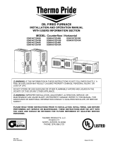
B. WIRING & SWITCHES
: TURN OFF THE ELECTRICAL POWER to the furnace before attempting to disconnect blower
wiring.
Figure 2: BOARD LAYOUT WITH SWITCHES

All installations and services must be performed by qualified service personnel.
3
C. Inputs
Power supplies
Line voltage is applied between the "S1" and "N1" quick connect terminals.
24 VAC Class II Transformer secondary voltage supplied to X and C
Limit Switch
The 120VAC limit switch is connected to pins P2-1 & 9. Refer to the Heat Mode section for the control
operation.
Thermostat call for heat "W"
24 VAC thermostat input. A call for heat is recognized when the thermostat connects "W" to "R". This
input has an indicator LED that will light when the control receives a call for heat. Refer to the Heat Mode
section for the control operation.
Thermostat call for cool, "Y"
24 VAC thermostat input. A call for cooling is recognized when the thermostat connects "Y" to "R. This
input has an indicator LED that will light when the control receives a call for cooling. . Refer to the Cool
Mode section for the control operation.
Thermostat call for dehumidification "DEHUM”
24 VAC thermostat input. A call for dehumidification is recognized when the humidistat connects
"DEHUM" to "R". This input has an indicator Led that will light when the control receives a call for
dehumidification. Refer to the Cool Mode section for the control operation.
Thermostat call for fan "G"
24 VAC thermostat input. A call for fan is recognized when the thermostat connects "G" to "R". This
input has an indicator LED in that will light when the control receives a call for fan. Refer to the Fan Mode
section for the control operation.
D. Outputs
ECM Control
The control controls a multiple speed ECM motor through the 6-pin P3 connector. This connector
provides connection for ECM Speed common (Pin 1), Speed output (Pin 2), Blower Enable (Pin 4), Cool
Enable (Pin 5) and “R” output (Pin 6).
Oil Burner
Control
The control provides dedicated contacts to operate the T-T input of an oil primary control. Rating
shall be class 2 - 24 VAC pilot duty @ 24 VAC (< 200mA).
Power
The switched 120VAC power from the LIMIT switch passes through the board between Pins 1&2
of connector P2.
Compressor contactor
The control provides switched 24VAC to operate a compressor contactor. Rating shall be class 2 - 24
VAC pilot duty @ 24 VAC (< 200mA).

All installations and services must be performed by qualified service personnel.
4
EAC (electronic air cleaner)
The control provides a 120VAC output for an electronic air Cleaner. This output is energized whenever the fan
motor is energized (either low, heat or cool speed). Connection is made via male quick connect terminal
labeled "EAC".
Humidifier
The control provides a 120 VAC output for a humidifier. Connections are made to a male quick connect
terminal labeled "EAC". In this application, the humidifier will operate on any blower operation. Humidifier
should be controlled by humidistat to prevent operation during cooling fan operation.
Status LED
A red LED is provided to indicate any thermostat input has been recognized by the microprocessor on the
control. See Diagnostic Features for a function description of operation.
Thermostat Input LEDs
Four green LEDs are placed beneath their respective thermostat connections (W, Y, G and DEHUM) and
operate whenever a call is present. See Diagnostic Features for a function description of operation.
E. Operating Modes
Standby Mode
All outputs are off and the control is waiting for a thermostat demand. The thermostat inputs, and limit switch
are continuously monitored. The control initiates action when a thermostat call is received or limit switch
opens.
Fan Mode
A call for fan ("G") is received from the thermostat. If no other mode is calling for blower operation, the
control will choose a “Low” speed value from the position of DIP switch SW1 positions 4 through 6, as
shown in the CFM Tables. and operate the fan at that speed. The fan mode will be operated as long as the
"G" input is calling and neither the Heat mode nor the Cool mode is calling for blower operation. When the
Heat and Cool modes call for blower operation, their respective outputs will take over after their respective
turn-on time delays have expired. The speed Output is present until the fan call is satisfied.
Cooling Mode
A call for cool ("Y") is received from the thermostat. If the heat mode is not active or the anti-short cycle delay
is not in effect, the control will energize the “CC” terminal. After a 10 second delay ramps up to the “COOL”
speed determined by the position of DIP switch SW1 (positions 4 through 6) determine a speed as shown in
CFM Tables.
When the call for cool is satisfied, the “CC” terminal is de-energized and the cooling off delay of 45 seconds is
started. Forty-five seconds later the blower speed ramps toward zero and the control reverts to Standby Mode.
Dehumidification Operation
If a call for dehumidification is received while the Cool Mode is active, blower speeds will be reduced.
The speed value will be selected from the LOW column of the CFM Tables.
Anti-Short Cycle Operation
To prevent compressor short cycling, a call for cooling will be ignored for four minutes after the
termination of any cooling call. The anti-short cycle delay is also in effect at power-up.

All installations and services must be performed by qualified service personnel.
5
Heat Mode
When a call for heat ("W") is received from the thermostat, if the “Cool” mode is not already active, the “T-T”
terminal is energized and the blower on delay is started. The on-off pattern of DIP switch SW2 (positions 1
and 2) select one of four blower on delay values (see Table 1). When the delay time has elapsed, a speed value
is read from DIP switch SW1 positions 1 through 3 (see the CFM Tables) and the blower is ramped up to that
speed.
The control remains in steady heat mode until the thermostat is satisfied. When the call for heat signal is
removed, the “T-T” terminal is de-energized and the blower off delay is started. The on-off pattern of DIP
switch SW2 (positions 3 and 4) select one of four blower off delay values (see Table 1). When the delay time
has elapsed, the blower is ramped toward zero.
Table 1: ON and OFF Blower Delay Time Switch Settings
Motor Blower Speed
Three blower speed outputs are provided. A “G” call for fan will provide the Low speed only. A “W”
heat call will provide the Heat speed only. A “Y” cooling call will provide the Cool speed only.
In the case of thermostat calls for “Y” and “W” together, blower speed selection will be determined by the
input that was first initiated. In the case where the control is in a cooling mode with both “Y” and “W”
inputs energized and then the “Y” input is removed, the cooling blower off time will be executed prior to
the control switching into a heating mode. In the case where the control is in a heating mode with both
“Y” and “W” inputs energized and then the “W” input is removed, the heating blower off time will be
executed prior to the control switching into a cooling mode. In the case where a call for fan “G” already
exists and either a “W” or a “Y” call is initiated, the blower speed will switch to the respective “W” or a
“Y” speed following the blower on delay for that call.
Six dip switches select Speed values for heat, cool, fan and dehumidification blower speeds (see the CFM
Tables).
Blower On and Off Delays
Four Heat blower on and four blower off delays are selected by two dip switches for each function. Refer
to Table 1 for specific delay values.
Speed Selection values
Three dip switches select 8 cooling speeds. Dependant fan, and dehumidification speeds are selected by
the same switches, their tabular values are enacted when their function is called.
Three additional dip switches select 8 heating speeds which are enacted when heat is called. This allows
independent selection of heating and cooling capacity parameters. See the CFM Tables for speeds.
DIP SWITCH 2 SECTION
STATE
BLOWER DELAY
TIMES
2 1 4 3 ON - SEC OFF - MIN
OFF OFF 30
OFF ON 60 Factory Set
ON OFF 120
ON ON 240
OFF OFF 2
OFF ON 4 Factory Set
ON OFF 6
ON ON 8

All installations and services must be performed by qualified service personnel.
6
F. CFM TABLES
The following tables contain blower speed settings and their respective air flowrates for the ECM blower motor. To
change air flowrates from that of the shipped settings, use the respective SW1 dipswitch on the furnace’s integrated
control board (see Figure 2).
CSHB60-90XE
Heating Speed Set-ups Cooling Speed Set-ups
Low Fire Med Fire High Fire
BTUH 60,000 72,000 90,000
Fan
Control
SW 1
Switch
Settings
Heating
CFM
Aprox. Rise
(F
0
)
Aprox. Rise
(F
0
)
Aprox. Rise
(F
0
)
3-OFF
2-OFF
1-OFF
740 75
o
80
o
3-OFF
2-OFF
1-ON
812 68
o
82
o
3-OFF
2-ON
1-OFF
883 63
o
76
o
84
o
Factory
SW1
Setting
3-OFF
2-ON
1-ON
968 57
o
69
o
86
o
3-ON
2-OFF
1-OFF
1054
63
o
79
o
3-ON
2-OFF
1-ON
1153
58
o
72
o
3-ON
2-ON
1-OFF
1267
66
o
3-ON
2-ON
1-ON
1424
58
o
Recommended Heating Speed Setting
Air Flow
Fan
Control
SW 1
Switch
Settings Clg. Tonage Cool Continous
6-OFF
5-OFF
4-OFF
2 799 500
6-OFF
5-OFF
4-ON
2.5 1017 508
6-OFF
5-ON
4-OFF
3 1210 605
6-OFF
5-ON
4-ON
3.5 1404 702
Factory
SW1
Setting
6-ON
5-OFF
4-OFF
4 1622 799

All installations and services must be performed by qualified service personnel.
7
II. ECM TROUBLE SHOOTING
A. DIAGNOSTC FEATURES
The control board is equipped with 4 green Input Status LEDs and 1 red Board Status LED. These are intended to
provide a quick view into furnace performance without requiring a voltmeter.
The green Input Status LEDs are driven by the “Y”, “W”, “G”, and “DEHUM” inputs and are located directly
below those inputs. They will light to indicate the presence of these signals.
The red Board Status LED has two functions:
It will light when the board recognizes a valid input signal and will stay lit until all valid signals are removed.
This is intended to show that the board is functioning and able to respond to input signals.
It will flash rapidly while120VAC is missing from the LIMIT switch. This is intended to give a quick visual
indication of the High LIMIT switch.
B. GENERAL GUIDELINES TO TROUBLESHOOTING GE ECM – DRIVEN SYSTEMS
: Disconnect power from unit before removing or replacing connectors, or servicing motor.
Wait at least 2 minutes after disconnecting power before opening motor.
SYMPTOM CAUSE/PROCEDURE
Motor rocks slightly when starting
• This is normal start-up for ECM
Motor won’t start
• No movement
• Check power at motor
• Check low voltage (24 VAC R to C) at motor
• Check low voltage connections
(G,PWM,W,R,C,) at motor
• Check for unseated pins in connectors on motor
harness
• Test with a temporary jumper between R – G
• Check motor for tight shaft
• Run Moisture Check
• Motor rocks, but won’t start • Check for loose or compliant motor mount
• Make sure blower wheel is tight on shaft
• Perform motor/control replacement check
Motor oscillates up & down while being tested off
of blower
• It is normal for motor to oscillate with no load on
shaft.
Motor starts, but runs erratically
• Varies up and down or intermittent
• Check line voltage for variation or “sag”
• Check low voltage connections
(G,PWM,W,R,C,) at motor, unseated pins in
motor harness connectors
• Check “Bk” for erratic CFM command (in
variable speed applications)
• Check-out system controls – T’stat?
• Perform Moisture Check
• “Hunts” or “puffs” at high CFM (speed) • Does removing panel or filter reduce “puffing”?
Reduce restriction
Reduce max airflow
• Stays at low CFM despite system call for cool or
heat CFM
• Check low voltage (T’stat) wires and connections

All installations and services must be performed by qualified service personnel.
8
• Verify fan is not in delay mode – wait until delay
complete
• “R” missing/not connected at motor
• Stays at high CFM • “R” missing/not connected at motor
• Is fan in delay mode? – wait until delay time
complete
• Blower won’t shut off • Current leakage from controls into G,Y or W?
Excessive noise
• Determine if it’s air noise, cabinet, duct or motor
noise – interview customer, if necessary
• Noisy blower or cabinet • Check for loose blower housing, panels, etc.
• High static creating high blower speed?
Check for air whistling thru seams in ducts,
cabinets or panels
Check for cabinet/duct deformation
• “Hunts” or “puffs” at high CFM (speed) • Does removing panel or filter reduce “puffing”?
Reduce restriction
Reduce max airflow
Evidence of Moisture
• Motor failure or malfunction has occurred and
moisture is present
• Replace motor and perform Moisture Check
• Evidence of moisture present inside air mover • Perform Moisture Check
DO
DON’T
• Check-out motor, controls, wiring and
connections thoroughly before replacing motor
• Automatically assume the motor is bad.
• Orient connectors down so water can’t get in
Install “drip loops”
• Locate connectors above 7 and 4 o’clock
positions
• Use authorized motor and control model #’s for
replacement
• Replace one motor or control model # with
another (unless an authorized replacement)
• Keep static pressure to a minimum:
Recommend high efficiency, low static
filters
Recommend keeping filters clean
Design ductwork for min static, max
comfort
Look for and recommend ductwork
improvement, where necessary, in
replacement
• Use high pressure drop filters – some have ½”
H
2
O drop!
• Use restricted returns
• Size the equipment wisely • Oversize system then compensate with low
airflow
• Check orientation before inserting motor
connectors
• Plug in power connector backwards
• Force plugs
Moisture Check
• Connectors are orientated “down” (or as recommended by equipment manufacturer)
• Arrange harnesses with “drip loop” under motor
• Is condensate drain plugged?
• Check for low airflow (too much latent capacity)
• Check for undercharged condition

All installations and services must be performed by qualified service personnel.
9
• Check and plug leaks in return ducts, cabinet
Comfort Check
• Check proper airflow settings
• Low static pressure for lowest noise
• Set low continuous-fan CFM
• T’stat in bad location?
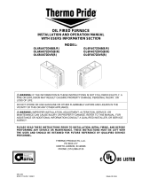
Figure 3: ECM PIN CONNECTORS
Troubleshooting table above and Figure 2 adapted from GE Industrial Systems publication GED-7161C,
“Troubleshooting GE ECM – Driven Systems”.
C. TROUBLESHOOTING CHARTS

All installations and services must be performed by qualified service personnel.
10
CONFIRM IF EITHER BLOWER
WHEEL IS RUBBING AGAINST
HOUSING OR MOTOR SHAFT
IS SPINNING FREELY, REPAIR
OR REPLACE AS NECESSARY.
DOES BLOWER SPIN FREELY?
IS THERE 115V
SUPPLIED TO MOTOR?
CHECK 115V SUPPLY,
CONNECTION FUSES,
SERVICE SWITCH AND
DOOR SWITCH.
CHECK HARNESS
CONNECTIONS
A
ND WIRE.
NO
YES
YES
YES
YES
NO
NO
NO
NO
NO
YES
YES
DISCONNECT 16 PIN
HARNESS FROM
MOTOR. IS THERE 12VDC
A
CROSS PIN12 & PIN1
A
ND PIN12 & PIN3
A
T THE HARNESS PLUG?
CHECK CONNECTION ON HARNESS AND MOTOR,
RECONNECT HARNESS TO MOTOR, IF
CONNECTIONS ARE GOOD AND MOTOR STILL
DOES NOT RUN REPLACE MOTOR.
THIS GUIDE SHOULD BE USED IN THE CASE OF A STOPPED OR MANFUNCTIONED ECM
BLOWER MOTOR. THE FOLLOWING SHOULD HELP ESTABLISH THE TYPE OF
MALFUNCTION OR DEVIATION FROM THE NORMAL BLOWER OPERATION.
TO USE THIS DIAGRAM, YOU JUST NEED TO FOLLOW THE INSTRUCTIONS IN THE BOXES.
CHECK 24VAC
SUPPLY
TO INTEGRATED CONTROL.
IS THERE 24VAC
A
CROSS R &
B/C ON THE
INTEGRATED
CONTROL?
REPLACE
INTEGRATED
CONTROL.
TURN THERMOSTAT MANUAL FAN
SWITCH ON (IF AVAILABLE) OR JUMPER
BETWEEN R & G ON INTEGRATED CONTROL.
IS THERE VOLTAGE GREATER THAN
12VDC BETWEEN PIN15 & PIN1?
CHECK CONNECTIONS AND WIRES
A
T INTEGRATED CONTROL, IF OK
REPLACE INTEGRATED CONTROL.
DISCONNECT 16PIN
HARNESS FROM
INTEGRATED CONTROL.
IS THERE 12VDC ACROSS
PIN 6 & PIN 1
A
T THE CONROL?

All installations and services must be performed by qualified service personnel.
11
BLOWER Off-
Delay Active?
Se
q
uence of O
p
eration
BURNER On
1. A/C Off
2. COOL mode Off
3.BLOWER Off-Delay Started
4. Status LED Off
BLOWER
= LOW
BLOWER = COOL
COOL
Mode On?
Y
Active?
On-Delay
Ended?
Yes Yes Yes
Yes
No No No
No
DEHUM
Active?
BLOWER = LOW
1. BLOWER Off (No Delay)
2. Status LED Off
1. HEAT mode On
2. BLOWER = HEAT
3. Status LED Flashes
1. COOL mode On
2. Blower On-Delay Started
3. Condenser On
4. Status LED On (continuous)
1. FAN mode On
2. BLOWER = LOW
3. Status LED On (continuous)
G Active?
Y Active?
LIMIT
Active?
FAN Mode
On?
G
Active?
W Active?
1. HEAT mode On
2. Blower On-Delay Started
3. Burner On
4. Status LED On (continuous)
Yes Yes
Yes
Yes
Yes
Yes
No No
No
No
No
No
Yes
No
1.BURNER Off
2. HEAT mode Off
3. BLOWER Off-Delay Started
4. Status LED Off
HEAT
Mode On?
W
Active?
LIMIT
A
ctive?
On-Delay
Ended?
Yes Yes Yes Yes
N
o
N
o
N
o
N
o

All installations and services must be performed by qualified service personnel.
12
Sequence of Operation Glossary
Inputs: LIMIT - 120vac power from the High Limit Switch used to power the burner.
W- Switched 24vac indicating a Heat call from the thermostat.
Y - Switched 24vac indicating a Cool call from the thermostat.
G - Switched 24vac indicating a call for blower operation from the thermostat.
DEHUM - Switched 24vac indicating a call for Dehumidification from a de-humidistat.
BLOWER Speeds:
HEAT - The Heating Blower speed selected by positions 1, 2 & 3 of SW1 (CFM tables on page 6)
COOL - The Cooling Blower speed selected by positions 4, 5 & 6 of SW1 (CFM tables on page 6)
LOW - The LOW Blower speed selected by positions 4, 5 & 6 of SW1 (CFM tables on page 6)
ECM – PSC Replacement
In an emergency situation, a defective ECM motor can be replace with a PSC motor to provide temporary
circulating air flow for heating or cooling. This is done by replacing the ECM motor in the motor mounting bracket
with a PSC motor of similar Horsepower. Wire the common lead (typically white) of the replacement PSC motor to
the neutral (common) terminal on the fan control board (N - 1 through 7). Connect the high-speed replacement PSC
motor lead (typically black) to the EAC terminal on the fan control board. The EAC contact is energized with
115VAC any time the control board is calling for fan operation whether in heating or cooling mode. This
replacement should be only used in emergency situations and only until a replacement ECM motor can be obtained
and reinstalled.
/