Page is loading ...

MO-437
ECN 5338-MA 140301 Made IN USA
OIL FIRED FURNACE
INSTALLATION AND OPERATION MANUAL
WITH USERS INFORMATION SECTION
MODEL:
OH6FA072D48B OH6FA072DV4B OH8FA119D60B OH8FA119DV5B
OH6FA072D48R OH6FA072DV4R OH8FA119D60R OH8FA119DV5R
OH6FA072D48N OH6FA072DV4N
OH6FX072DV4R
WARNING: IF THE INFORMATION IN THESE INSTRUCTIONS IS NOT FOLLOWED EXACTLY, A
FIRE OR EXPLOSION MAY RESULT CAUSING PROPERTY DAMAGE, PERSONAL INJURY, OR
LOSS OF LIFE.
DO NOT STORE OR USE GASOLINE OR OTHER FLAMMABLE VAPORS AND LIQUIDS IN THE
VICINITY OF THIS OR ANY OTHER APPLIANCE.
WARNING: IMPROPER INSTALLATION, ADJUSTMENT, ALTERATION, SERVICE, OR
MAINTENANCE CAN CAUSE INJURY OR PROPERTY DAMAGE. REFER TO THIS MANUAL. FOR
ASSISTANCE OR ADDITIONAL INFORMATION CONSULT A QUALIFIED INSTALLER, OR SERVICE
AGENCY.
PLEASE READ THESE INSTRUCTIONS PRIOR TO INSTALLATION, INITIAL FIRING, AND BEFORE
PERFORMING ANY SERVICE OR MAINTENANCE. THESE INSTRUCTIONS MUST BE LEFT WITH
THE USER AND SHOULD BE RETAINED FOR FUTURE REFERENCE BY QUALIFIED SERVICE
PERSONNEL.
THERMO PRODUCTS, LLC.
PO BOX 217
NORTH JUDSON, IN 46366
PHONE: (574) 896-2133

i
CONTENTS
SECTION PAGE
I. SAFETY SECTION 1
A. CODES AND CLEARANCES 3
B. MAKE-UP AIR 4
II. GENERAL INSTRUCTIONS 5
A. CHIMNEY 6
B. VENTING 10
C. DRAFT REGULATORS 11
D. DUCT WORK/AIR CONDITIONING 11
E. AIR FILTER(S) 15
F. LIMIT POSITION AND LOCATION 17
G. BURNER INSTALLATION 18
H. BURNER SPECIFICATIONS AND APPLICATIONS 19
I. OILTANK AND PIPING 22
J. OIL FILTER 23
K. ELECTRICAL WIRIING 23
L. BLOWER SETUP 27
M. BLOWER CONTROLLER INFORMATION FOR PSC MOTOR 35
N. STARTUP PROCEDURES 40
III. USERS INFORMATION SECTION 48
A. OIL SUPPLY 48
B. COMBUSTION AIR SUPPLY 48
C. INSPECTION AREAS 48
D. STARTING THE BURNER 49
E. FILTER CLEANING AND LOCATION 49
IV. INSTALLER'S INSTRUCTIONS TO USER 50
V. DEALER MAINTENANCE 51
A. GENERAL INSPECTION 51
B. HEAT EXCHANGER 52
C. HEAT EXCHANGER CLEANING INSTRUCTIONS 52
D. ELECTRICAL SYSTEM 54
E. SUPPLY/RETURN AIR BLOWER 54
F. SUPPLY/RETURN AIR FILTER 54
G. EXTENDED APPLIANCE SHUTDOWN 55
VI. HOMEOWNER/USER INFORMATION AND ROUTINE MAINTENANCE 56
VII. TROUBLESHOOTING 58
A. DIAGNOSTICS 59
B. CAD CELL CHECK-OUT PROCEDURE 59
VIII. SEQUENCE OF OPERATIONS FLOW CHART 61
IX. TROUBLE SHOOTING FLOW CHART 63
APPENDIX – A
REPLACEMENT PARTS LIST 69
APPENDIX – B
WIRING DIAGRAMS 71

ii
Model Number Digit
1
2
3
4
5
6
7
8
9
10
11
12
Fuel
Configuration
Heat Exchanger
Identifier
Flue
Feature
Capacity
Capacity
Capacity
Blower Type
Clg Airflow Cap.
Clg Airflow Cap.
Burner
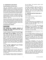
Oil Furnace Model Nomenclature Example Model Numbers
O
H
6
F
A
0
7
2
D
4
8
B
O
H
6
F
A
0
7
2
D
V
4
R
O
H
8
F
A
1
1
9
D
6
0
B
O
H
8
F
A
1
1
9
D
V
5
R
O = Oil
O
H = Highboy D = Downflow
H
6 = Heat Exchanger Size Identifier
6
F = Front
F
R = Rear
R
A = Single Stage
A
X = 2-Stage
X
Heating Capacity MBTUH (000's) with factory installed nozzle
0
7
2
D = Direct Drive
D
Clg. Airflow: Example = 48MBTUH = 4 tons @ 400cfm/ton
4
8
Clg. Airflow Variable Speed (ECM) V5 = 5tons
V
5
B = Beckett, R = Riello, N = Beckett NX
B

1
I. SAFETY SECTION
This page and the following contains various warnings and cautions found
throughout the Oil Furnace Manual. Please read and comply with the statements
below.
WARNING AND CAUTIONS:
WARNING: This furnace is not to be used as a construction heater. See Page 3
WARNING: The predetermined limit locations on all of the Thermo Pride oil fired
furnaces have been tested and approved by Thermo Products, LLC. Any attempt to
relocate these safety controls or replace these safety controls with a control that is not
approved, or is incompatible, may result in personal injury, substantial property damage
or death. See Page 17
WARNING: THE HEAT EXCHANGER MUST BE CLEANED BY A QUALIFIED
SERVICE PERSON. See Page 52
CAUTION: DO NOT ATTEMPT TO MAKE REPAIRS YOURSELF! See Page 48
WARNING: The area around the furnace should be kept free and clear of
combustible liquids and material, especially papers and rags. See Page 3
WARNING: NEVER burn garbage or refuse in your furnace. Never try to ignite
oil by tossing burning papers or other material into your furnace. See Page 48
WARNING: Thermo Products oil furnaces are designed to burn No. 1 or No. 2
distillate fuel oil. NEVER USE GASOLINE OR A MIXTURE OF OIL AND GASOLINE.
See Page 48
CAUTION: DO NOT ATTEMPT TO START THE BURNER WHEN:
1. Excess oil has accumulated,
2. The furnace is full of vapors
3. The combustion chamber is very hot.
IF ONE OR MORE OF THESE CONDITIONS EXIST, CONTACT A QUALIFIED
SERVICE PERSON. See Page 48
WARNING: DO NOT START BURNER UNLESS BLOWER DOOR IS SECURED IN
PLACE.

2

3
The entire text of these instructions must be read and understood, before
installing the appliance. It is the installer's responsibility to do the following:
1. Inform and demonstrate to the user, the correct operation and maintenance of the appliance, as
explained in the Homeowner/User Information and Routine Maintenance section of this manual.
2. Inform the user of the hazards of flammable liquids and vapors and to remove such liquids and
vapors from the vicinity of the appliance.
3. Inform the user of all pertinent warnings and precautions concerning this appliance.
WARNING: This unit is not to be used for temporary heating of buildings, or structures, under
construction. Construction dust may enter the appliance or the duct system and cause a fire hazard.
Certain chemicals used during construction when burned, form corrosive condensate that can
substantially reduce the life of the heating system heat exchanger.
This appliance is shipped completely assembled and internally wired. All electrical wiring has been factory
installed and inspected. At the time of installation, the unit will require connection to electric power, fuel oil
supply, and supply and return air ductwork. In the event of a shortage of parts or damage, contact
Thermo Pride office.
This unit uses a fan-assisted combustion system, consisting of a pressure atomizing, oil burner and
combustion air blower, used to push the products of combustion through the heat exchanger system.
After installation, the furnace and duct system must be adjusted to obtain a temperature rise of 51°F to
81°F through the unit. (Refer to the rating label located on side panel inside the burner compartment).
The installation must conform with local codes or, in the absence of local codes, with the Standard for the
Installation of Oil-Burning Equipment, NFPA 31-1997, or the latest edition, and to these instructions. The
installation must also comply with CSA B139 for recommended installation practices where applicable.
A. CODES AND CLEARANCES:
The following items must be considered when choosing the size and location of the unit.
1. All local codes and/or regulations take precedence over the instructions in this manual and
should be followed accordingly. In the absence of local codes, installation must conform to these
instructions and the guidelines of the National Fire Protection Association (NFPA). Two applicable
NFPA installation codes are the National Electrical Code, ANSI/NFPA 70-1999, and Standard for the
Installation of Oil-Burning Equipment, NFPA 31-1997. The latest editions of these codes should be
consulted.
2. The selection of a heating unit should be based on a rate of heat loss calculation for the residence
according to the manuals provided by the Air Conditioning Contractors of America (ACCA) or the
American Society of Heating, Refrigeration, and Air Conditioning Engineers (ASHRAE). The heating
capacity of the unit proposed for installation should meet or slightly exceed the rate of heat loss for the
residence. Over sizing should not exceed 25% of the heat loss calculation.
3. When installed, this unit should be level. If possible, it should be installed in a central location, with
respect to outlet registers of the supply air ductwork.
4. Definitions of "combustible" and "non-combustible" materials as presented in the 1996 version of the
National Fuel Gas Code, ANSI Z223.1-1996/NFPA 70-1996, are as follows:
a. Combustible material:
“...materials made of or surfaced with wood, compressed paper, plant fibers, or
other materials that are capable of being ignited and burned. Such materials
shall be considered combustible even though flame proofed, fire-retardant
treated, or plastered.”

4
b. Non-combustible material:
“...material that is not capable of being ignited and burned; such as material
consisting entirely of, or a combination of, steel, iron, brick, concrete, slate,
asbestos, glass, and plaster.”
: Carefully read and thoroughly understand the following guidelines and warnings
before continuing with the installation of this appliance. Failure to follow these guidelines can
cause improper and unsafe operation of this appliance. Unsafe operation can result in substantial
property damage, severe personal injury, or death.
1. This appliance shall be used with only the type of fuel oil for which it is approved. Refer to the
appliance-rating label for the required type of fuel.
2. This appliance is an oil-fired furnace designed for installation on non-combustible materials. This
appliance is also approved for attic installation on non-combustible materials.
3. Ensure that adequate combustion and ventilation air is available to the unit.
4. The airflow resistance of the duct system attached to this appliance must fall within the allowable
external static pressure range for this unit. Refer to the Airflow Requirements and Sizing of
Ductwork section of this manual.
5. Make sure supply and return air ducts are completely sealed to the appliance casing. Refer to the
Airflow Requirements and Sizing of Ductwork section of this manual.
This area in which the furnace is located must have adequate supply of air for combustion and draft control
operation. The minimum required volume of free air should be 50ft³/1000 btu (per NFPA 54). However, if the
furnace is located in an area of the building that doesn’t meet this requirement, two openings into another room
are recommended (each opening having a free area of 1 square inches per 1,000 BTUH input of the total input
of all appliances located in the room). If these openings are in a wall, they must be at least 6 inches from the
ceiling and floor (Fig. 1A) or they are in a door, they must be at least 6 inches from the top of the door and 6
inches from the bottom of the door (Fig. 1B). THESE OPENINGS MUST BE FREE AND UNOBSTRUCTED.
Fig 1: Properly Positioned Combustion Air Openings In Walls (Fig. 1A) and Doors (Fig. 1B).
B. MAKE-UP AIR: Today's emphasis on home insulation increases the probability of inadequate air
supply to the furnace. Heavy insulation cuts off infiltration of outside air, which previously replaced inside
air removed by bathroom, kitchen and laundry vent fans, and air escaping up chimneys. This causes a
negative pressure differential within the home that reduces the supply of air available to the furnace for
combustion and ventilation.
The Thermo Pride Make-Up-Air Control, installs quickly and easily on any warm air heating system,
delivers controlled, fresh air automatically during the winter and a constant supply of clean, fresh air for
comfortable summer living. It resolves the negative pressure differential problem.

5
II. GENERAL INSTRUCTIONS - READ BEFORE START OF INSTALLATION
1. The heating output capacity of the furnace proposed for installation should be based on a heat loss
calculation made according to the manuals provided by the Air Conditioning Contractors of America
(ACCA) or the American Society of Heating, Refrigeration and Air Conditioning Engineers, Inc.
(ASHRAE).
2. All local codes and/or regulations take precedence over the instructions in this manual and should be
followed accordingly. In the absence of local codes, installation must conform with these instructions and
regulations of the National Fire Protection Association, and to the provisions of the National Electrical
Code (ANSI/NFPA 70-1999 or latest edition).
3. The installed furnace must be level and positioned in a central location with respect to outlet registers.
It should be located near the chimney to minimize any horizontal run of flue pipe, which may be required.
4. A furnace installed in a residential garage must be installed so the burner and ignition source are
located higher than 18 inches above the floor. The furnace must also be located or protected to avoid
physical damage by vehicles.
WARNING: This furnace is not to be used as a construction heater.
5. Listed below are definitions of "COMBUSTIBLE MATERIAL" and "NON-COMBUSTIBLE MATERIAL."
Combustible Material: is made of or surfaced with wood, compressed paper, plant fibers, plastics, or
other material that will ignite and burn, whether flame resistant or not.
Non-Combustible Material: is material that is not capable of being ignited and burned. Such materials
consist entirely of, or a combination of, steel, iron, brick, tile, concrete, slate, or glass.
Table 1: MINIMUM CLEARANCES TO COMBUSTIBLE MATERIALS
TYPE OF
UNIT
MODEL NO.
1
FROM
SIDES OF
FURNACE
FRONT
TOP &
SIDES OF
PLENUM
FROM THE
FLUE/VENT
REAR
Highboy
OH6FA072D*** 0” Note
1
1” 7” 0”
Highboy
OH8FA119D*** 0” Note
2
1” 8” 0”
Note:
1
OH6 front clearance 6” for Closet, 24” for Alcove.
2
OH8 front clearance 8” for Closet, 24” for Alcove.
The minimum clearances listed in the preceding table are for fire protection. Clearance for servicing the
front of the furnace should be at least 24 inches.
NOTE: The OH6 & OH8 furnaces are approved for closet installation. If the OH6 is installed in a closet, it
requires two openings in the closet door for combustion air, each having a minimum area of 162 sq.
inches. The OH8 requires two openings in the closet door, each having a minimum area of 181 sq.
inches. This free area intentionally exceeds the recommended minimum free area of 1 square inch per
1000 BTUH of input rate.

6
A. CHIMNEY:
The furnace must be connected to an adequate chimney or an approved vent in accordance with these
instructions. An adequate chimney is one that is sealed and lined with the capability of producing a (-).04"
WC flue draft and having the capacity to handle the amount of stack gases that are introduced into it. A
chimney with an internal construction of corrosion resistant tile, stainless steel, or some other material
that will withstand flue gas temperatures up to 900°F is required.
Qualified service personnel must perform all installations and services.
The following are common chimney requirements necessary for the furnace to operate correctly:
A masonry chimney serving a Thermo Pride oil fired furnace must comply with local codes and NFPA
Standard for Chimneys, Fireplaces, Vents, and Solid Fuel Burning Appliances (NFPA211-1996 or latest
edition).
1. PREVENTION OF CHIMNEY CONDENSING:
Stack gas may do one of two things as it escapes up the chimney:
A. Remain entirely in a gaseous state if the internal chimney wall temperature is above the dew
point
B. Condense water vapor on the chimney walls if they are chilled below the dew point.
Condensing will always occur on chimney walls whose temperatures are below the dew point, but the
condensate may evaporate when the walls warm above the dew point. If the chimney wall temperature
does not exceed the dew point during the heating cycle of the furnace, the moisture may accumulate in
large enough quantities to cause problems such as corrosion of a metal chimney (especially plain steel or
galvanized steel), erosion and break up of a tile liner in a masonry chimney and, in severe cases,
corrosion of the heat exchanger. Condensate also could enter the home through cracks or joints in the
chimney in a worse case situation.
Condensation most likely will not occur at the bottom of the chimney because the stack gas heats the
chimney walls as it rises and the bottom will be heated first. This heating of the walls will cause the stack
gas temperature to drop, which in turn may reduce the stack gas temperature below dew point, causing
condensation to appear on the upper part of the chimney first. This condensation may then run down
inside the chimney and drip back as far as the flue pipe and heat exchanger, where corrosion may occur,
if not treated.
To prevent condensation, it is necessary that the internal chimney wall temperature always be kept above
the dew point. If the chimney is a masonry type, it may have to be fitted with a flue liner, when the
temperature loss is too great for the furnace. If the chimney is a metal type, then an "all fuel" chimney
must be used, such as a Class "A" triple wall or insulated metal chimney. A liner will act as an insulator
and reduce the stack gas temperature loss. Insulation may be added around the liner for further
temperature stability. If the chimney is on the home's exterior or passes through a sizable, unheated area
of the building, such as a porch, high ceiling attic, etc., and condensing occurs, the chimney must be
insulated around its exterior to help the flue hold its temperature. Also, check to see if the chimney is too
large for the furnace and other appliances connected to it. If so, reduce to proper size (see Appendix E of
NFPA31) by lining. Be sure to use stainless steel liners, such as stainless types 430, 304, or for the
toughest corrosion problems, type 316. If the chimney is the correct size for the unit and condensing still
occurs, then insulating the vent connector and/or reducing the efficiency of the furnace may have to be
done to raise the chimney temperature.
More detailed information may be obtained from the latest edition of the ASHRAE HVAC Systems and
Equipment Handbook.

7
2. PROPER CHIMNEY HEIGHT:
The chimney shall terminate at least 3 feet above the highest point where it passes through the roof of a
building and at least 2 feet higher than any portion of a building within a horizontal distance of 10 feet.
(See Fig. 2a).
Fig. 2: Proper chimney termination height for pitched roofs
If the chimney penetrates a roof more than 10 feet from a ridge, wall or parapet, a minimum of 3 feet
above roof or exit point must be maintained. See Figure 2b.
If the roof is flat rather than the normal residential pitched roof, refer to Figure 3 for proper clearances.
Fig. 3: Proper chimney termination height for flat roofs
3. PROPER VENT CONNECTOR PIPE/CHIMNEY CONNECTION:
The vent connector pipe should extend only to (and not beyond) the inside wall of the chimney (See Fig.
4). A thimble should be used to connect the vent connector pipe to the chimney so that the vent
connector pipe may be readily removed in case of inspection or replacement.
Fig. 4: Proper insertion of the vent connector in the chimney.

8
4. PROPER CHIMNEY BOTTOM LEVEL:
In cases where the chimney extends to the basement floor, the draft can usually be improved by filling the
base of the chimney with sand to within 12 inches of the vent connector pipe after relocating the clean-out
door. (See Fig. 5).
Fig. 5: Suggested method to improve chimney draft.
5. TIGHT JOINTS:
All joints of the chimney must be tightly sealed. The inside of the chimney should be free of any
obstructions, such as loose brick, broken pieces of tile, or corroded metal.
6. TIGHT CLEAN-OUT DOORS AND CONNECTIONS:
All chimney clean-out doors and flue connections must fit tightly so they will seal to avoid air leaks.
7. NO INTERCONNECTED CHIMNEY FLUES:
If chimney flues are divided or there are multiple flues within one chimney, make sure there are no
openings in the partition separating the divided or individual flues.
8. FLUE PIPE CLEARANCES, SIZING AND TYPE:
The vent connector pipe must not pass through a combustible wall or partition unless adequate protection
is provided at the passageway. An acceptable passageway could be either an approved, ventilated metal
thimble which is at least 12 inches larger in diameter than the vent connector pipe, or brick work which is
at least 8 inches thick constructed into the wall and surrounding the vent connector pipe. (See Fig. 6) on
the next page.
Fig. 6: Suggested method to accommodate vent connector passage through a wall composed of a combustible material.

9
Fig. 7: Alternate constructions that allow reduced clearances to combustible materials.
REDUCTION OF CLEARANCES WITH SPECIFIED FORMS OF PROTECTION:
Type of protection applied to and covering all surfaces of combustible material within the distance
specified as the required clearance with no protection unless otherwise noted, all dimensions in inches,
refer to Fig. 7.
Required clearance with no protection from the appliance or
chimney connector is:
18 inches
9 inches
6 inches
Sides &
Sides &
Sides &
Above Rear
Above Rear
Rear
a. 3-1/2" thick masonry wall without ventilation air space….
-- 12
-- 6
-- 5
b. 1/2" insulation board over 1" glass fiber or mineral wool batts…
12 9
6 5
4 3
c. 0.024(24 gauge) sheet metal over 1" glass fiber or mineral
wool batts reinforced with wire on rear face with ventilated air
space…
9 6
5 3
3 3
d. 3- 1/2" thick masonry wall with ventilation air space..
-- 6
-- 6
-- 6
e. 0.024 (24 gauge) sheet metal with ventilated air space.
9 6
5 3
3 2
f. 1/2" thick insulation board with ventilation air space..
9 6
5 3
3 3
g. 0.024 ( 24 gauge) sheet metal with ventilated air space over
0.024 (24 gauge) sheet metal with ventilated air space….
9 6
5 3
3 3
h. 1" glass fiber or mineral wool batts sandwiched between two
sheets 0.024 (24 gauge) sheet metal with ventilated air space
9 6
5 3
3 3
A. Equal the required clearance with no protection.
B. Equals the reduced clearance permitted in accordance with the preceding clearance chart.
C. The protection applied to the construction that covers the combustible material should extend far enough
in each direction to make C equal to A.
The vent connector pipe between the furnace and chimney shall be of equal diameter as the flue outlet of the
furnace. The vent connector pipe must be made of 24 gauge (or thicker) corrosion-resistant steel. The
vent connector pipe should be as short as possible and installed so that it has a continuous rise from the
furnace to the chimney. The horizontal length of a connector to a natural draft chimney or vent serving a single
appliance shall not be more than 75 percent of the height of the vertical portion of the chimney or vent above
the connector. Elbows should be minimized and the pipe should be joined with metal screws and supported by
straps. All horizontal runs of vent connector pipe should be pitched upward a minimum of ¼ inch per foot of run.
A thimble should be used to connect the vent connector pipe to the chimney so the pipe may be readily
removed in case of inspection or replacement. See Fig. 6 on preceding page.

10
B. VENTING:
NOTE: On the OH6 & OH8 it is possible to rotate the flue elbow (which is factory installed for vertical
discharge) 90°
counter clockwise from the vertical position to adapt to various venting systems. The OH8
flue elbow can also be rotated 90°
clockwise.
Notice: Blocked Vent Switch Installation
The blocked vent switch kit must be installed to comply with CAN STD B140.4 where applicable. For
installation instructions see AOPS2687 kit.
CAUTION MUST BE TAKEN NOT TO EXCEED 90° ROTATION (OF THE FLUE
ELBOW) .
ROTATION OF FRONT FLUE ELBOW:
When an installation requires that the flue exit out the left (or right OH8 only) side casing, remove screw
securing the 90 deg. elbow and rotate it 90°. Then, remove knock-out in side casing and extend vent
through the opening.
A trim collar may be ordered from Thermo Products to hide the gap around the flue pipe. This trim collar,
however, is not required for operation. Trim collar/gasket part numbers(s) 14121 / 330073 for OH6 and
14132 / 330006 for OH8.
The OH6 & OH8 may be vented through a standard correctly sized chimney.
The OH6 & OH8 may also be horizontally vented through a sidewall. Thermo Products has available the
Field model FDVS-45/FOVP-415 and FDVS-67/FOVP-615 side wall vent kits for such applications. When
installing the sidewall vent kits, outside combustion air must also be applied to the burner. The following
table identifies application order information.
Table 2: Sidewall vent kits
The Field vent kit is set up with 4 inch diameter vent pipe for OH6 and 6 inch diameter vent pipe for the
OH8 with concentric through-the-wall vent termination/inlet air vent hood. The combustion air inlet pipe
diameter is also 4 inch diameter. For Riello, the combustion air inlet pipe will be reduced to 3 inch
diameter with the Riello sidewall vent kit. For Beckett, the combustion air inlet pipe will be reduced to 3”
diameter with the Beckett sidewall vent kit.
The side wall vent may be installed either through the knock-out on the right or left side casing of the unit
or vertically out the top opening of the vestibule.
The combustion air inlet can be installed through the either the lower left side casing knockout or the
lower right side casing knockout.
FIELD VENT TERMINATION
KIT
SIDE WALL VENT
ACCESSORIES KIT
COMBUSTION AIR INTAKE
HOOD KIT
(15’ application MAX)
(BURNER SPECIFIC)
(FOR COMBUSTION AIR
APPLICATIONS ONLY)
THERMO PRODUCTS PART
NUMBER
THERMO PRODUCTS
PART NUMBER
THERMO PRODUCTS PART
NUMBER
(OH6) (OH8)
Beckett AFG AOPS8393 AOPS8414
AOPS8394 AOPS8397
Riello BF3
AOPS8393 AOPS8414 AOPS8395
AOPS8416
Beckett NX
(OH6 ONLY)
AOPS8393 N/A AOPS8412 AOPS8413
BURNER
SIDE WALL VENTING APPLICATION ORDER INFORMATION

11
C. DRAFT REGULATORS:
Note: Do not use with Direct Vent application.
A draft regulator is supplied with the furnace and should be installed according to the regulator
manufacturers recommendations. With the burner operating, use a draft gauge to adjust the regulator to
the proper setting. (refer to the instructions enclosed with draft regulator to adjust to the proper setting).
When the burner air supply and draft are properly adjusted, the over fire draft should be a negative (-).01"
to (-).02" WC, as measured at the 5/16" over fire air tap (See Fig. 12). This tap is provided in the upper
burner mounting plate. To measure the flue draft, punch a small hole in the vent connector pipe as close
to the furnace as possible and always before the draft regulator.
Note: Draft over fire may be positive for high fire applications but not to exceed (+).02" WC.
D. DUCT WORK/AIR CONDITIONING:
If the furnace is used in connection with summer air conditioning (cooling), the furnace should be installed
parallel with or on the upstream side of the evaporator coil to avoid condensation in the furnace heat
exchanger. If the cooling unit is installed with a parallel flow arrangement, dampers or other means used
to control flow of air should be provided to prevent chilled air from entering the furnace. If such a damper
is manually operated, it must be equipped with a means to prevent operation of either unit, unless the
damper is in the full heat or cool position.
The duct system should again follow the current design standard of Air Conditioning Contractors of
America (ACCA) or ASHRAE Fundamentals volume. The most common location for the A-shaped coil (A
style) is shown in Fig. 8.
Fig 8: Acceptable locations for the air conditioner evaporator coil.
NOTICE: The minimum coil pan clearance for a sectional or drum type heat exchanger is three inches
unless specified otherwise by the individual coil manufacturer.
NOTICE: The minimum return air temperature is 55° F.
Airflow Requirements and Sizing of Duct Work:
The duct system must be sized and installed by a qualified installer or service person, following the
design standards of the Air Conditioning Contractors of America (ACCA) or the American Society of
Heating, Refrigeration, and Air Conditioning Engineers (ASHRAE). This furnace has been designed to
operate against a maximum external static pressure of 0.5 in. W.G. This is equivalent to 0.1 in.
W.G. supply, and 0.1 in. W.G. return, and 0.3 in. W.G. for evaporator coil.

12
1. Supply and return air ducts have to be furnished by the installer and run between the appliance,
which must be installed outdoors, and the interior of the structure the appliance serves. These ducts
must be sealed to the casing of the appliance.
2. To reduce the transmission of vibration and noise to the duct system and to reduce flexure of the duct
system due to thermal expansion and contraction, it is recommended that flexible joints be installed at
the supply and return duct connections to the unit.
3. The return air duct system must equal the supply air duct system in the flow capacity (CFM) for a
given pressure drop. Use a supplier's catalog for proper sizing of outlet and return air registers and
grills to ensure that they meet the flow requirements of the run to which they are connected.
4. The duct system shall be sized to provide the maximum airflow rate (CFM) required of the installation.
Two common rules for determining minimum airflow in heating and cooling systems follow:
a. For heating, 14 CFM of airflow are required per 1000 BTU/hr of heat output, based on
steady state operation and a 51° to 81° temperature rise.
b. For cooling, 400 CFM of airflow are required per ton of air conditioning. (For reference, a
ton of A/C = 12,000 BTU/hr removed from the space.)
Refer to Examples 1 & 2, (page 15) for a sample calculation of how to determine the required
minimum airflow rate.
5. Duct sizing is based upon both air velocity and pressure drop considerations. When possible, current
practice favors designing ductwork for lower air velocities. (For residences, a maximum air velocity of
800 FPM is suggested.) This results in quieter duct systems, systems which require less fan power
(reduced operating costs), and less carefully constructed ductwork (lower initial costs).
However, lower air velocities also result in larger duct sizes than necessary at higher velocities. In
some cases, space restrictions may limit the ductwork to smaller than optimal sizes.
6. The following method can be used to size ductwork when air velocities are low to moderate.
a. Using a floor view of the residence, determine, or layout, the locations of the supply registers
and the return air grills. (Generally, supply registers should be located close to sources of
heat loss, i.e. windows and doors, around the perimeter of the building. Return grills should
be located in central positions as far away from the supply registers as practical.)
b. Find a location for the appliance that minimizes the amount of ducting required to connect the
appliance to the supply and return air duct systems. Consider issues of access to the oil
supply and electrical service, required service and venting clearances, and operating noise
when selecting this location.
c. Plan an efficient layout for the ductwork connecting each of the supply air registers in the
supply system to the unit. Plan and layout ductwork connecting each of the return air grills in
the return system to the unit. Measure or estimate the length of duct between each register
and grill.
d. Select values for the airflow through each register and grill.
e. Select values for the pressure drops of both the supply and return air systems. Each branch
of the supply (or the return) air system will have this pressure drop. The total pressure drop of
the supply and return air systems added together cannot exceed the maximum external static
pressure that can be supplied by the appliance blower.
f. Determine the required flow rate for each branch of the supply and return air systems. The
total airflow rate, by adding the airflow rate of each branch of the supply system, must equal
the minimum required airflow rate (refer to part 3, above). Likewise, the airflow rate of each of
the branches of the return air system must sum to the required minimum flow rate.

13
g. Using the selected air flow rates for each component of the duct system and manufacturer’s
literature, or published literature on duct system pressure drops, the pressure drop for each
component in the duct system can be estimated.
The ASHRAE Handbook – Fundamentals is an excellent source of duct system design principles
and pressure drop data. Conversely, for a specified type of fitting, it is also possible to determine
the required size or diameter of the component for a specified pressure drop and flow rate.
h. The resistance of the take-off and the outlet register (or return grill) should then be summed
together to determine the total pressure drop for each branch. This value should be close to
the assumed value for the pressure drop of the system. If it is not close, then flow rates for
each branch must be adjusted, or the design of the duct system must be altered, to give the
proper pressure drops. Usually, the cross-sectional area of the ductwork should be changed
in order to adjust the pressure drop to a suitable value. Refer to Example 2, (page 14) for a
sample calculation of how to use this method for sizing the supply side ductwork for a
residence.
Table 3 shows the air handling capacities of 100-ft. lengths of circular and rectangular
ductwork based on a 0.1 in. W.G. static pressure drop. The first column to the right is the
airflow rate and the second is the required diameter for a circular duct. The third column is
the required cross-sectional area of the duct and the other columns to the left are rectangular
ducts with sufficient cross-sectional area to handle the flow at the specified pressure drop.
[For lengths of ductwork less than 100 ft., simply multiply 0.1 in. W.G. by the ratio of the
actual duct length (in feet) over 100 ft. for the approximate pressure drop.] Use the supplier’s
catalog for proper sizing of outlet air registers and return air grills to insure that they provide
the required flow rate at the desired pressure drop.

14
Table 3: Suggested Duct Sizes for Homes, Quiet Offices, Or Similar Installations
(Based on a 0.1 in. W.G. static pressure drop per 100 ft. of duct.)
7. The supply and return air ducts, or flexible joints, should be carefully secured and sealed to the
appliance housing to prevent air leakage from, or into, the duct system. For best performance,
insulate the outside surfaces of the ducts to reduce heat loss from, or heat gain to, the ducts.
8. As a final step in the installation, the appliance must be adjusted to deliver a temperature rise within
the range of 51° to 81°F. Adjust the blower motor speed to obtain a temperature rise within the
acceptable range. The required blower speed will depend on the airflow resistance of a supply and
return air duct systems.
Fig. 9: Supply air duct sizing Example
The RETURN AIR DUCT SYSTEM should equal the warm air duct system in airflow capabilities.
NOTE: When a return register is located in the same room as the furnace, the register must be at least 20
feet away from the furnace.

15
SIZING THE DUCT WORK FOR A COMBINATION HEATING AND COOLING SYSTEM:
Two formulas must be used in determining the CFM requirements of a combustion heating and cooling
system.
1. HEATING CFM:
HEAT OUTPUT OF FURNACE (BTUH)
1.1 X TR (TEMPERATURE RISE, °F) = HEATING(CFM)
EXAMPLES:
A. 110,000 BTUH OUTPUT
1.1 X 85°F TR = 1176 CFM FOR HEATING
B. 110,000 BTUH OUTPUT
1.1 X 70°F TR = 1429 CFM FOR HEATING
2. COOLING CFM: 400 CFM X COOLING TONNAGE (12,000 BTUH PER TON)=AIRFLOW FOR
COOLING(CFM)
EXAMPLES:
A. 400 CFM X 3 TON (12,000 BTUH) = 1,200 CFM FOR COOLING
1TON
B. 400 CFM X 2.5 TON (12,000 BTUH) = 1,000 CFM FOR COOLING
1 TON
IMPORTANT: SIZE THE DUCT SYSTEM FOR THE LARGER OF THE TWO AIRFLOW
REQUIREMENTS.
E. Air Filter Mounted External to Furnace:
On highboy furnaces, it is necessary to cut the return air opening in the side, rear casing or base,
depending upon the needs of the specific installation.
The filter rack provided with the furnace, refer to Fig. 10a & 10b, will serve as a template to scribe a mark
for the return air opening on the casing. Place the filter rack on a side casing approximately one inch up
from the bottom of the furnace and centered from side to side. Place the securing flange against the
casing when locating the return air opening. For your convenience, (4) locator knockouts have been
placed at the proper locations on both the left and right side casings.
PLEASE NOTE: While scribing the return air opening, the filter rack can be held in position by tape or
similar temporary means.
Position the open end of the filter rack so as to provide access for filter replacement. Once the filter rack
is positioned correctly, scribe a line along the inside of the securing flange on three of the sides. To scribe
a line on the fourth side (the open end), use the open-end support as a guide.
Remove the filter rack and cut the return air opening in the casing. Now the filter rack can be anchored to
the furnace with screws or pop-rivets through the securing flange of the filter rack.

16
Connect the return air plenum to the filter rack and slide the filter into place. Dimensions for adapting the
return air plenum to the filter rack are provided (See Fig. 10a & 10b).
Fig. 10a: A typical filter rack and dimensions for the OH6 furnace.
Fig. 10b: A typical filter rack and dimensions for the OH8 furnace.
: Failure to comply with minimum filter installation requirements may affect the
performance and/or void the warranty on this unit.
If a method other than Thermo Pride filter racks is selected for retention of the filter and/or use of a
different filter type is desired, refer to Table 4 below for minimum sizing guidelines for selecting filter for
the unit.

17
Filter Type
Maximum
Air Velocity
(ft/min)
Model Number
OH6
OH8
*Thermo Products
Supplied Permanent
600 384 in² 480 in²
Standard
Permanent
500 461 in² 576 in²
Disposable 300 768 in² 960 in²
Table 4: Minimum Required Filter Area (in square inches)
* The Thermo Products supplied filter can be cut to size to fit other filter retention systems as
long as the maximum air velocity is not exceeded.
NOTICE: Any internal stiffeners used in the filter must not be removed, although
they can be cut to size as needed.
F. LIMIT POSITION AND LOCATION
WARNING: The predetermined limit locations on all of the Thermo Pride oil fired furnaces have been
tested and approved by Thermo Products, LLC. Any attempt to relocate these safety controls or replace
these safety controls with a control that is not approved, or is incompatible, may result in personal injury,
substantial property damage or death.
The unit listed in the table below must have the limit control installed at the time of unit installation.
Fig. 11: Limit location for OH6 & OH8
TABLE 5: Installation location of
the fan and limit control for each
furnace
/