Page is loading ...

Assembly Instructions
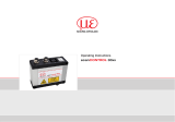
scanCONTROL 25xx/26xx/29xx
Protection housing /
Protection and cooling housing
Use
In dirty environments and with increased ambient temperatures, it is recommended to operate
the scanner with a protection and/or cooling housing. The protection and cooling housings are
optional accessories. Their use may impair the linearity of the sensor in the complete system
which is why a referenced measurement is recommended. Installation of the scanners into the
protective housings should be performed by the manufacturer
The scanner may only be operated within the limits specified in the technical data. The scanner
must be used in such a way that no persons are endangered or machines are damaged in case
of malfunctions or total failure of the scanner. Take additional precautions for safety and damage
prevention for safety-related applications.
Variants
- Protection housing with blow-out system and air supply connection, article 2105058
- Protection housing with blow-out system, air supply connection and water connections for
cooling, article 2105059
Protection housing scanCONTROL LLT25xx/26xx/29xx
Adaptive protection housing for
scanCONTROL 25xx/26xx/29xx
- Measuring ranges 25 - 100 mm
- Air supply of the optical path
- Exchangeable protective glass
Protection and cooling housing scanCONTROL LLT25xx/26xx/29xx
Adaptive protection and cooling housing for
scanCONTROL 25xx/26xx/29xx
- Measuring ranges 25 - 100 mm
- Air supply of the optical path
- Exchangeable protective glass
- Water cooling circuit for sensor cooling
(ambient temperatures up to 95 °C)
X9771381-A021119SWE
MICRO-EPSILON MESSTECHNIK
GmbH & Co. KG
Koenigbacher Str. 15 · 94496 Ortenburg
www.micro-epsilon.com
Proper Environment
- Protection class: IP65 (applies only when the sensor cable is plugged in)
Optical inputs are excluded from protection class. Contamination leads to impairment or failure
of the function.
- Min. cooling capacity: 940 W
- Max. sensor temperature: 45 °C
- Maximum pressure: 3 bar
- Only fluid cooling media are permissible. Air/gas cooling is not possible.
Unpacking / Included in Delivery
- 2 cooling plates (only with protection and cooling housing)
- 2 base plates
- 1 protective plate
- 2 protective glasses
Sensor Mounting, Dimensions
The scanCONTROL sensors are optical sensors for measurements with micrometer accuracy.
i
Pay attention to careful handling during mounting and operation.
Mount the sensor only to the existing mounting holes/threaded holes on a flat surface.
Clamps of any kind are not permitted and can lead to failure of the sensor.
13
73
ø6
1.5
0
7
17
88.5
90.5
103.5
4
0
14
73
75
88
49
0
65
71
8
1x air connection
Adjustable
splash guard
3x Mounting
holes M4
Exchangeable
protective glass
Protection housing with blow-out system, article 2105058
0
0
11.25
0
15
48
51.75
63
71
76.9
128.8
117
4
14
75
88
17
90.5
88.5
103.5
5x ø6
7
73
1.5
1x air
connection
Exchangeable
protective glass
4x water
connection
Adjustable
splash guard
3x mounting
hole M4
Protection housing with blow-out system and water cooling, article 2105059
1
2
9
4 5 6
3
7
8
9
8
2
1
4 5 6
Part Description
1 Protective glass slot
2 Object carrier
3
Cooling plate, left
(only with water
cooling)
4 Base plate, left
5 Scanner
6 Base plate, right
7
Cooling plate, right
(only with water
cooling)
8
Heat-conductive
pad (only with water
cooling)
9 Protective plate
Protection housing assembly

Mounting of Protection and Cooling Housing
If the protection or cooling housing is installed subsequently, make sure that the product labels are
removed from the scanner (on the sides).
Join the right base plate to the pro-
tective glass slot. Insert the right
cooling plate. Centering pins hold
the cooling plate in place.
Remove the protective film from
the heat-conducting pad.
Join the scanner to the right cool-
ing plate.
Join the left base plate to the left
cooling plate.
Remove the protective film from
the heat-conductive pad on the left
cooling plate and join the left base
plate with the left cooling plate to
the sensor.
Join the left base plate with the left
cooling plate to the scanner.
i
Pressing the scanner onto the protective glass slot in order to avoid gap formation en-
sures proper function of the blow-out system.
Tighten the fastening screw M5x16
with a torque of 3.5 Nm.
Slightly tighten the adjusting screw on the base plates by hand as far as it will go in order to
ensure proper heat dissipation. Screw back by 1/2 turn. The pitch of the adjusting screw is 0.75
mm/turn.
i
Make sure that the ball bearing is half compressed when installed in order to achieve the
optimal tolerance compensation. This is why the adjusting screw must be turned back by
1/2 turn after being slightly tightened to the stop.
Push the protective glass from the
front into the slot as far as it will go.
Mount the protective plate at
the laser entrance window. For
fastening, use the allen screw
(M4x8) and the set screw (M4x10)
included in the scope of supply.
2M laser class
7 7
6
LLT29xx-10/BL
LLT29xx-25/BL,
50/BL,100/BL
8
658
8
5
LLT26xx/29xx
LASER RADIATION
DO NOT STARE INTO BEAM
OR EXPOSE USERS OF
TELESCOPE OPTICS
CLASS 2M LASER PRODUCT
IEC 60825-1: 2014
P ≤ 8 mW , P ≤ 8 mW ; H≤ 52 W/m²;
0 P
λ = 658 nm; F = 0...4 kHz, t = 1 µs...∞
LLT25xx
3B laser class
Mounting of Protection Housing
Join the scanner to the left base
plate with the protective glass slot.
Join the right base plate to the
scanner.
i
Pressing the scanner onto the protective glass slot in order to avoid gap formation ensures
proper function of the blow-out system.
Tighten the fastening screw M5x12
with a torque of 3.5 Nm.
Push the protective glass from the front into the protective glass slot as far as it will go.
Mount the protective plate at the
laser entrance window. For fas-
tening, use the allen screw (M4x6)
and the set screw (M4x6) included
in the scope of supply.
Laser Class Marking
The scanCONTROL 25xx/26xx/29xx sensors operate with a semiconductor laser with a wa-
velength of 658 nm (visible/red) or 405 nm (visible/blue).
The operation of the laser is indicated by an LED on the sensor.
The laser warning signs are concealed by the protection housings or had been removed prior to
mounting. Additional stickers (warning signs etc.) are included in the delivery.
Stick the signs according to the laser class of your scanner on the protection or cooling
housing, front and rear.
/


