Page is loading ...

- 1 -
Preface
About Our Company
WayinTop, Your Top Way to Inspiration, is a professional manufacturer over 2,000 open source
motherboards, modules, and components. From designing PCBs, printing, soldering, testing,
debugging, and offering online tutorials, WayinTop has been committed to explore and demystify
the wonderful world of embedded electronics, including but not limited to Arduino and
Raspberry Pi. We aim to make the best designed products for makers of all ages and skill levels.
No matter your vision or skill level, our products and resources are designed to make electronics
more accessible. Founded in 2013, WayinTop has grown to over 100+ employees and a 50,000+
sq ft. factory in China by now. With our unremitting efforts, we also have expanded offerings to
include tools, equipments, connector kits and various DIY products that we have carefully
selected and tested.
US Amazon Store Homepage:
https://www.amazon.com/shops/A22PZZC3JNHS9L
CA Amazon Store Homepage:
https://www.amazon.ca/shops/A22PZZC3JNHS9L
UK Amazon Store Homepage:
https://www.amazon.co.uk/shops/A3F8F97TMOROPI
DE Amazon Store Homepage:
https://www.amazon.de/shops/A3F8F97TMOROPI
FR Amazon Store Homepage:
https://www.amazon.fr/shops/A3F8F97TMOROPI
IT Amazon Store Homepage:
https://www.amazon.it/shops/A3F8F97TMOROPI
ES Amazon Store Homepage:
https://www.amazon.es/shops/A3F8F97TMOROPI
JP Amazon Store Homepage:
https://www.amazon.co.jp/shops/A1F5OUAXY2TP0K

- 2 -
Real Time Clock Kit
with Arduino_DS3231RTC_SSD1306 OLED
Overview
This tutorial shows how to build a real time clock and timing alarm clock
using Arduino DS3231RTC and SSD1306 OLED. The DS3231RTC is used as
a real time clock chip which keeps the time running even if the main
power supply is off (with the help of a battery), time, date and
temperature of nano board are displayed on the SSD1306 OLED.
This digital clock mainly uses the arduino nano board to read the time of
the DS3231 clock module, and then controls the OLED display the real
time. When the time reaches the set reminder time, the buzzer will
automatically sound. The clock can also monitor the real-time
temperature of the system, and the time can be adjusted manually.
Parts Required
Arduino Nano Board x 1(With USB Download Cable)
DS3231 Real Time Clock Module x 1
0.96”OLEDDisplay Module x1
5V Active buzzer x 1

- 3 -
Tactile Push Button Switch x 2
Dupont Wires x N
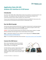
Connection Diagram

- 4 -
Arduino Control Program
Before using the control program, you need to load the Adafruit_GFX.h
and Adafruit_SSD1306 library functions required by the system.
Step 1: Open the arduino IDE, select "Sketch"-> "Include Library"->
"Manage Libraries ...." as shown below.
Step 2: Enter "Adafruit_GFX" in the pop-up window to search for library
functions, and then install the Adafruit GFX Library functions, as shown
below, which has installed the library functions.。

- 5 -
Step 3: After installating the Adafruit GFX Library library function, enter
"Adafruit_SSD1306" in the input text box to search for the SSD1306 library
function, and then install Adafruit SSD1306, as shown in the figure below.
Step 4: After the installation is completed, close arduinoIDE, and then find
the "Adafruit_SSD1306.h" file in the "Adafruit_SSD1306" library function

- 6 -
file that was just loaded (the path of this file is different, it will usually be
under the "libraries" file in the arduino installation directory, or in arduino
The "libraries" file under the code file storage path. Mine is under the "C: \
Users \ Admin \ Documents \ Arduino \ libraries \ Adafruit_SSD1306" path),
as shown below.
Step 5: Open the file in Notepad and find the location shown below.
Step 6: Uncomment "#define SSD1306_128_64", and then comment
"#define SSD1306_128_32". as the picture shows. Save and exit after
making changes.

- 7 -
Step 7: Open arduinoIDE and select "File"-> "New" and create a new
project file, as shown in the figure below.
Step 8: Copy the following program into the newly created project.
#include <SPI.h>
#include <Wire.h>
#include <Adafruit_GFX.h>

- 8 -
#include <Adafruit_SSD1306.h>
#define SCREEN_WIDTH 16 // OLED display width, in pixels
#define SCREEN_HEIGHT 16 // OLED display height, in pixels
#define OLED_RESET 4
Adafruit_SSD1306 display(OLED_RESET);
#define button1 9 // Button B1 is connected to Arduino pin 9
#define button2 8 // Button B2 is connected to Arduino pin 8
#define buzzer 3
void setup(void) {
pinMode(button1, INPUT_PULLUP);
pinMode(button2, INPUT_PULLUP);
pinMode(buzzer, OUTPUT);
digitalWrite(buzzer, HIGH);
delay(1000);
Serial.begin(115200);
// by default, we'll generate the high voltage from the 3.3v line internally! (neat!)
display.begin(SSD1306_SWITCHCAPVCC, 0x3C); // initialize with the I2C addr
// init done
// Clear the display buffer.
display.clearDisplay();
display.display();
display.setTextColor(WHITE,BLACK);
display.drawRect(117, 55, 3, 3, WHITE); // Put degree symbol ( ° )
draw_text(0, 55, "TEMPERATURE =", 1);
draw_text(122, 55, "C", 1);
}
char Time[] = " : : ";
char Calendar[] = " / /20 ";
char temperature[] = " 00.00";
char temperature_msb;
byte i, second, minute, hour, day, date, month, year, temperature_lsb;
void display_day(){
switch(day){
case 1: draw_text(0, 0, " SUNDAY ", 1); break;

- 9 -
case 2: draw_text(0, 0, " MONDAY ", 1); break;
case 3: draw_text(0, 0, " TUESDAY ", 1); break;
case 4: draw_text(0, 0, "WEDNESDAY", 1); break;
case 5: draw_text(0, 0, "THURSDAY ", 1); break;
case 6: draw_text(0, 0, " FRIDAY ", 1); break;
default: draw_text(0, 0, "SATURDAY ", 1);
}
}
void DS3231_display(){
// Convert BCD to decimal
second = (second >> 4) * 10 + (second & 0x0F);
minute = (minute >> 4) * 10 + (minute & 0x0F);
hour = (hour >> 4) * 10 + (hour & 0x0F);
date = (date >> 4) * 10 + (date & 0x0F);
month = (month >> 4) * 10 + (month & 0x0F);
year = (year >> 4) * 10 + (year & 0x0F);
// End conversion
Time[7] = second % 10 + 48;
Time[6] = second / 10 + 48;
Time[4] = minute % 10 + 48;
Time[3] = minute / 10 + 48;
Time[1] = hour % 10 + 48;
Time[0] = hour / 10 + 48;
Calendar[9] = year % 10 + 48;
Calendar[8] = year / 10 + 48;
Calendar[4] = month % 10 + 48;
Calendar[3] = month / 10 + 48;
Calendar[1] = date % 10 + 48;
Calendar[0] = date / 10 + 48;
if(temperature_msb < 0){
temperature_msb = abs(temperature_msb);
temperature[0] = '-';
}
else
temperature[0] = ' ';
temperature_lsb >>= 6;
temperature[2] = temperature_msb % 10 + 48;
temperature[1] = temperature_msb / 10 + 48;
if(temperature_lsb == 0 || temperature_lsb == 2){
temperature[5] = '0';
if(temperature_lsb == 0) temperature[4] = '0';

- 10 -
else temperature[4] = '5';
}
if(temperature_lsb == 1 || temperature_lsb == 3){
temperature[5] = '5';
if(temperature_lsb == 1) temperature[4] = '2';
else temperature[4] = '7';
}
draw_text(60, 0, Calendar, 1); // Display the date (format: dd/mm/yyyy)
draw_text(10, 24, Time, 2); // Display the time
draw_text(75, 55, temperature, 1); // Display the temperature
if(Time[0]=='2' && Time[1]=='0' && Time[3]== '3' && Time[4]=='0')
{
digitalWrite(buzzer, LOW);
}
else
{
digitalWrite(buzzer, HIGH);
}
}
void blink_parameter(){
byte j = 0;
while(j < 10 && digitalRead(button1) && digitalRead(button2)){
j++;
delay(25);
}
}
byte edit(byte x_pos, byte y_pos, byte parameter){
char text[3];
sprintf(text,"%02u", parameter);
while(!digitalRead(button1)); // Wait until button B1 released
while(true){
while(!digitalRead(button2)){ // If button B2 is pressed
parameter++;
if(i == 0 && parameter > 31) // If date > 31 ==> date = 1
parameter = 1;
if(i == 1 && parameter > 12) // If month > 12 ==> month = 1
parameter = 1;
if(i == 2 && parameter > 99) // If year > 99 ==> year = 0
parameter = 0;
if(i == 3 && parameter > 23) // If hours > 23 ==> hours = 0

- 11 -
parameter = 0;
if(i == 4 && parameter > 59) // If minutes > 59 ==> minutes = 0
parameter = 0;
sprintf(text,"%02u", parameter);
draw_text(x_pos, y_pos, text, 1);
delay(200); // Wait 200ms
}
draw_text(x_pos, y_pos, " ", 1);
blink_parameter();
draw_text(x_pos, y_pos, text, 1);
blink_parameter();
if(!digitalRead(button1)){ // If button B1 is pressed
i++; // Increament 'i' for the next parameter
return parameter; // Return parameter value and exit
}
}
}
void draw_text(byte x_pos, byte y_pos, char *text, byte text_size) {
display.setCursor(x_pos, y_pos);
display.setTextSize(text_size);
display.print(text);
display.display();
}
void loop() {
if(!digitalRead(button1)){ // If button B1 is pressed
i = 0;
while(!digitalRead(button1)); // Wait for button B1 release
while(true){
while(!digitalRead(button2)){ // While button B2 pressed
day++; // Increment day
if(day > 7) day = 1;
display_day(); // Call display_day function
delay(200); // Wait 200 ms
}
draw_text(0, 0, " ", 1);
blink_parameter(); // Call blink_parameter function
display_day(); // Call display_day function
blink_parameter(); // Call blink_parameter function
if(!digitalRead(button1)) // If button B1 is pressed
break;

- 12 -
}
//set position of text when editing on button press
date = edit(60, 0, date); // Edit date
month = edit(80, 0, month); // Edit month
year = edit(110,0, year); // Edit year
hour = edit(14, 9, hour); // Edit hours
minute = edit(50, 9, minute); // Edit minutes
// Convert decimal to BCD
minute = ((minute / 10) << 4) + (minute % 10);
hour = ((hour / 10) << 4) + (hour % 10);
date = ((date / 10) << 4) + (date % 10);
month = ((month / 10) << 4) + (month % 10);
year = ((year / 10) << 4) + (year % 10);
// End conversion
// Write data to DS3231 RTC
Wire.beginTransmission(0x68); // Start I2C protocol with DS3231 address
Wire.write(0); // Send register address
Wire.write(0); // Reset sesonds and start oscillator
Wire.write(minute); // Write minute
Wire.write(hour); // Write hour
Wire.write(day); // Write day
Wire.write(date); // Write date
Wire.write(month); // Write month
Wire.write(year); // Write year
Wire.endTransmission(); // Stop transmission and release the I2C bus
delay(200); // Wait 200ms
}
Wire.beginTransmission(0x68); // Start I2C protocol with DS3231 address
Wire.write(0); // Send register address
Wire.endTransmission(false); // I2C restart
Wire.requestFrom(0x68, 7); // Request 7 bytes from DS3231 and release I2C
//bus at end of reading
second = Wire.read(); // Read seconds from register 0
minute = Wire.read(); // Read minuts from register 1
hour = Wire.read(); // Read hour from register 2
day = Wire.read(); // Read day from register 3
date = Wire.read(); // Read date from register 4
month = Wire.read(); // Read month from register 5
year = Wire.read(); // Read year from register 6
Wire.beginTransmission(0x68); // Start I2C protocol with DS3231 address

- 13 -
Wire.write(0x11); // Send register address
Wire.endTransmission(false); // I2C restart
Wire.requestFrom(0x68, 2); // Request 2 bytes from DS3231 and release I2C
//bus at end of reading
temperature_msb = Wire.read(); // Read temperature MSB
temperature_lsb = Wire.read(); // Read temperature LSB
display_day();
DS3231_display(); // Diaplay time & calendar
delay(50); // Wait 50ms
}
Step 9: Use the hardware connected with the data cable to connect to the
computer, and then set the hardware parameters in arduinoIDE. The
specific settings are shown in the figure below.

- 14 -
Step 10: After the setting is completed, select the first button to compile
the program. If there are no errors, select the second button to upload the
program to the arduino nano board. As shown below.
Step 11: The alarm clock of this tutorial is set at "20:30". If you need to
change it, please modify the code shown in the figure below.
Step 12: The final Experiment map is shown below. Press and hold the
button connected to the D9 pin of the Arduino nano board for about 3
seconds to enter the time setting function. After entering, just short press

- 15 -
to select the next data. After selecting the data to be set, press the key
connected to the D8 pin of the Arduino nano board to change the data.

- 16 -
/