Lantech IPGS-0008B User manual
- Category
- Network switches
- Type
- User manual
This manual is also suitable for

Lantech
I(P)GS-0008B
8 10/100/1000T (PoE at/af) Industrial
Unmanaged Ethernet Switch
I(P)ES-0008B
8 10/100TX (PoE at/af) Industrial Unmanaged
Ethernet Switch
User Manual
V1.15
Nov. 2022

Recommendation for Shielded network cables
STP cables have additional shielding material that is used to reduce external interference. The
shield also reduces the emission at any point in the path of the cable. Our recommendation is
to deploy an STP network cable in demanding electrical environments. Examples of
demanding indoor environments are where the network cable is located in parallel with
electrical mains supply cables or where large inductive loads such as motors or contactors are
in close vicinity to the camera or its cable. It is also mandatory to use an STP cable where the
power device (like IP camera) is used outdoors or where the network cable is routed outdoors.

Content
Overview ............................................................ 1
Introduction .............................................................. 1
Model Lists ............................................................... 1
Packing List .............................................................. 2
Safety Precaution ..................................................... 2
Hardware Description ......................................... 3
Front Panel ............................................................... 3
Top View .................................................................. 4
Dimensions .............................................................. 5
Wiring the Power Inputs ........................................... 7
Wiring the Fault Alarm Contact ................................ 7
LED Indicators .......................................................... 9
RJ-45 Pin Assignments .......................................... 10
Cabling ................................................................... 12
Mounting Installation ........................................ 13
DIN-Rail Mounting .................................................. 13
Wall-Mount Plate Mounting .................................... 15


1
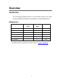
Overview
Introduction
The unmanaged industrial switch is a cost-effective solution and meets
the high reliability requirements demanded by industrial applications.
Model Lists
Model name
10/100/1000T
ports
10/100TX
ports
PoE ports
IPGS-0008B
8
-
8
IPGS-0008B-6
8
-
6
IPES-0008B
-
8
8
IPES-0008B-6
-
8
6
IGS-0008B
8
-
NA
IES-0008B
-
8
NA
For latest product specifications, please refer to Lantech official site.

2
Packing List
1 x 8-port Industrial Ethernet Switch
1 x Terminal Block
Safety Precaution
Attention
If DC voltage is supplied by an external circuit, please use a
protection device on the power supply input.

3
Hardware Description
In this paragraph, we will introduce the Industrial switch’s dimensions,
port, cabling information, and wiring installation.
For POE models: Do not use units' POE ports to uplink to another POE switch in
vehicle applications. (May Cause Damage) Lantech strongly advise the installation
of a Galvanic isolated DC/DC converter between the power supply and the Ethernet
switch on all Non-Isolated models. Please contact the sales team for advice on
which models support isolated power design.
For PoE 48V models, the output voltage of power supply must exceed 48VDC
for 802.3af and 53VDC for 802.3at operation.
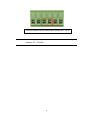
Front Panel
The Front Panel of the IGS-0008B/IPGS-0008B/
IES-0008B/IPES-0008B is shown as below.

4
Front Panel of the Industrial Switch
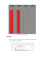
Top View
The top panel of the Industrial Switch is equipped one terminal block
connector of two DC power inputs.
Top panel of the Industrial Switch Converter

5
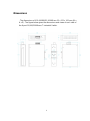
Dimensions
. The dimensions of IGS-0008B/IES-0008B are 35 x 152 x 105 mm (W x
H x D). The figure below gives the dimensions and views of each side of
the 8-port 10/100/1000Base-T Industrial Switch.

6
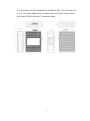
The dimensions of IPGS-0008B/IPES-0008B are 43 x 152 x 105 mm (W x
H x D). The figure below gives the dimensions and views of each side of
the 8-port 10/100/1000Base-T Industrial Switch.

7
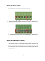
Wiring the Power Inputs
Please follow the steps below to insert the power wire.
1. Insert the positive and negative wires into the V+ and V- contacts on the
terminal block connector.
2. To tighten the wire-clamp screws for preventing the DC wires to loose.
Wiring the Fault Alarm Contact
The fault alarm contact is in the middle of terminal block connector as the
picture shows below. Inserting the wires, it will detect the fault status
which the power is failure or port link failure (for managed model) and form
an open circuit.

8
Note
The wire gauge for the terminal block should be in the range
between 12~ 24 AWG.
Insert the wires into the fault alarm contact (No. 3 & 4)

9
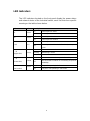
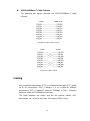
LED Indicators
The LED indicators located on the front panel display the power status
and network status of the Industrial switch; each has their own specific
meaning as the table shown below.
LED
Color
Description
P1
Green
On
Power input 1 is active
Off
Power input 1 is inactive
P2
Green
On
Power input 2 is active
Off
Power input 2 is inactive
Fault
Red
On
Power input 1 or 2 is inactive
Off
Power input 1 and 2 are both functional, or no power
inputs
1 ~ 8
(Upper LED)
Green
On
Connected to network
Flashing
Networking is active
Off
Not connected to network
1 ~ 8
(Lower LED)
Yellow
On
Connected to network at speed of 1000Mbps
Off
Not connected to network or not working at speed of
1000Mbps
PoE
(PoE model)
Green
On
The port is operating in PoE mode
Off
The port is not operating in PoE mode

10
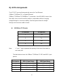
RJ-45 Pin Assignments
The UTP/STP ports will automatically sense for Fast Ethernet
(10Base-T/100Base-TX) or Gigabit Ethernet
(10Base-T/100Base-TX/1000Base-T) connection. Auto MDI/MDIX means that
the switch can connect to another switch or workstation without changing
straight through or crossover cabling. See the figures below for straight
through and crossover cable schema.
10/100Base-TX Pinouts
Pin Number
Assignment
1
Tx+
2
Tx-
3
Rx+
6
Rx-
Note
“+” and “-” signs represent the polarity of the wires that make up
each wire pair.
The table below shows the 10Base-T/100Base-TX MDI and MDI-X port
pinouts.
Pin Number
MDI-X Signal Name
MDI Signal Name
1
Receive Data plus (RD+)
Transmit Data plus (TD+)
2
Receive Data minus (RD-)
Transmit Data minus (TD-)
3
Transmit Data plus (TD+)
Receive Data plus (RD+)
6
Transmit Data minus (TD-)
Receive Data minus (RD-)

11
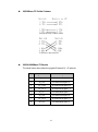
10/100Base-TX Cable Schema
Straight Through Cable Schema
Crossover Cable Schema
10/100/1000Base-T Pinouts
The table below describes the gigabit Ethernet RJ-45 pinouts.
Pin
Signal name
Description
1
BI_DA+
Bi-directional pair A+
2
BI_DA-
Bi-directional pair A-
3
BI_DB+
Bi-directional pair B+
4
BI_DC+
Bi-directional pair C+
5
BI_DC-
Bi-directional pair C-
6
BI_DB-
Bi-directional pair B-
7
BI_DD+
Bi-directional pair D+
8
BI_DD-
Bi-directional pair D-

12
10/100/1000Base-T Cable Schema
The following two figures illustrate the 10/100/1000Base-T cable
schema.
Straight Through Cable Schema
Crossover Cable Schema
Cabling
Use unshielded twisted-pair (UTP) or shielded twisted-pair (STP) cable
for RJ-45 connections: 100Ω Category 3, 4 or 5 cable for 10Mbps
connections, 100Ω Category 5 cable for 100Mbps, or 100Ω Category
5e/above cable for 1000Mbps connections.
The cable between the switch and the link partner (switch, hub,
workstation, etc.) must be less than 100 meters (328 ft.) long.

13
Mounting Installation
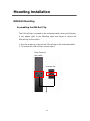
DIN-Rail Mounting
Assembling the DIN-Rail Clip
The DIN-rail clip is screwed on the industrial switch when out of factory.
If not, please refer to the following steps and figure to secure the
DIN-rail clip on the switch.
1, Use the screws to screw on the DIN-rail clip on the industrial switch.
2, To remove the DIN-rail clip, reverse step 1.
Rear Panel of
the switch
DIN-rail clip

14
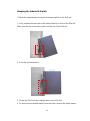
Hanging the Industrial Switch
Follow the steps below to hang the industrial switch on the DIN rail.
1, First, position the rear side of the switch directly in front of the DIN rail.
Make sure the top of the clip hooks over the top of the DIN rail.
2, Push the unit downward.
3, Check the DIN-Rail clip is tightly fixed on the DIN rail.
4, To remove the industrial switch from the track, reverse the steps above.

15
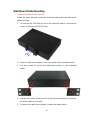
Wall-Mount Plate Mounting
*Optional Wall Mount Kit required
Follow the steps below to mount the industrial switch with the wall mount
plates included.
1. To remove the DIN-Rail clip from the industrial switch, unscrew the
screws to remove the DIN-Rail clip.
2. Place the wall-mount plates on the rear panel of the industrial switch.
3. Use the screws to secure the wall-mount plates on the industrial
switch.
4. Use the hook holes at the corners of the wall-mount plates to hang the
industrial switch on the wall.
5. To remove the wall-mount plates, reverse the steps above.

16
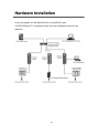
Hardware Installation
In this paragraph, we will describe how to install the 8-port
10/100/1000Base-TX Industrial Switch and the installation points for the
attention.
Page is loading ...
Page is loading ...
-
 1
1
-
 2
2
-
 3
3
-
 4
4
-
 5
5
-
 6
6
-
 7
7
-
 8
8
-
 9
9
-
 10
10
-
 11
11
-
 12
12
-
 13
13
-
 14
14
-
 15
15
-
 16
16
-
 17
17
-
 18
18
-
 19
19
-
 20
20
-
 21
21
-
 22
22


Lantech IPGS-0008B User manual
- Category
- Network switches
- Type
- User manual
- This manual is also suitable for
Ask a question and I''ll find the answer in the document
Finding information in a document is now easier with AI
Related papers
-
Lantech IES-0016 User manual
-
-
-
-
-
-
-
-
-
Other documents
-
Eks EC 5TX PoE Injektor Owner's manual
-
 3onedata ES2010G-2GF User manual
-
Han Networks AP311H Installation guide
-
Intellisystem IT-IPS-715-IM-1GC-4-POE Owner's manual
-
-
 Shenzhen 3onedata Technology ES208G User manual
-
-
Planet IGS-614HPT User manual
-
-

