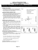
INSTALLATION INSTRUCTIONS
FOR P5570-44B/66A & P5571-44B/66A
WA R N I N G ! S H U T P O W E R O F F AT F U S E O R C I R C U I T B R E A K E R .
A V E R T I S S E M E N T ! C O U P E R L E C O U R A N T A U N I V E A U D E S F U S I B L E S O U D O D I S J O N C T E U R
Page: 1/1
Fig. 2
PREPARING FOR INSTALLATION (Fig. 1)
1.
Shut off power at the fuse box or circuit breaker box and
remove the old fixture including the mounting hardware.
2.
Carefully unpack your new fixture and lay out all the parts in
a clear area. Take care not to misplace any small parts
necessary for installation.
SUGGESTED INSTALLATION (Fig. 1 and Fig. 2)
3. Remove two mounting screws (E) from the side of
canopy
(D) and remove mounting plate (B).
4. Attach mounting plate (B) to the junction box (not
included) with the two outlet box screws (C) provided.
5. Loosen allen screw (H) with allen w
rench (F) provided,
determine the designed height for hanging wire (I), then
tighten allen screw (H) with allen wrench (F) provided.
CONNECTING THE WIRES (Fig. 2)
6. Connect the electrical wires as sho
wn in Fig. 2, making
sure that all wire connectors are secured. If your junction
box
has a ground wire (green or bare copper), connect the
fixture’s ground wire to it. Otherwise, connect the fixture’s
ground wire directly to mounting plate (B) using the gree
n
screw provided. Tuc
k the wire connections neatly into the
junction box.
COMPLETING THE INSTALLATION (Fig. 1)
7. Attach canopy (D) to
mounting plate (B) and secure it with
mounting screws (E).
8. Install (1) one medium base bulb (K) up to 60 watt
s or CFL
or LED equivalent (not included) to the socket (J).
Your installation is now complete. Return power to the
junction box and test the fixture.
Fig.1
set# A-021-114D
- Mounting plate
- Ground screw
- Mounting screws*2pcs
FIXTURE
WIRES
Black or
Smooth
HOUSE
WIRES
Black
(Hot)
FIXTURE
WIRES
White or
Ribbed
HOUSE
WIRES
White
(Neutral)
FIXTURE
WIRES
Bare
Copper
(Ground)
HOUSE
WIRES
Green
(Ground)
/


