Page is loading ...

digital audio
modular
processing system
C8000
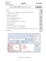
8, 4, 2 Channel Audio Delay
C8685
1/11
features
• 8Ch / 4Ch / 2Ch variable audio delay
• 1,36sec. / 2,72sec. / 5,44sec. maximum delay times
• Setup of delay times in ms (coarse) and samples (offset)
• Automatic display of delay times in frames and ms
• bit transparent for Non Audio (e.g. Dolby E) signals
• Remote control via C8702 Frame Controller, GPI/O or
http based API
block diagram

digital audio
modular
processing system
C8000
8, 4, 2 Channel Audio Delay
C8685
2/11
technical specifications
AUDIO :
resolution : 24bit
sample rate : 32...48kHz
audio processing : 8 / 4 / 2 channel audio delay
Delay times:
8Ch 0ms … 1,36sec.
4Ch 0ms … 2,73sec.
2Ch 0ms … 5,46sec.
GENERAL :
backplane connector : ref. to DIN41612, 64pin, a+b, male
power supply : +5V DC
power consumption : approx. 150mA
dimension : 3RU, 4HP, 160mm depth
temperature : 10°C … 40°C
humidity : 90%, non condensing

digital audio
modular
processing system
C8000
8, 4, 2 Channel Audio Delay
C8685
3/11
location of switches:
initial set up / bus assignment
For the initial setup the CAN ADDRESS selection is the most important setting. To avoid address conflicts
with other C8k modules the CAN address setting must be done with care, because each CAN address
has to be unique! See C8k System manual for details.
The Dip-Switch #4 serves as +16 address range extension for the CAN address switch.
The Dip-Switch #1 is the BUS-EN switch which turns the audio driver circuits on when power is turned on.
This allows you to insert a new module into an existing system without the risk of disturbing signals on
other busses, if the actual bus configuration is unknown.
The INIT button will initialize the module to factory default if one holds it down while power up.

digital audio
modular
processing system
C8000
8, 4, 2 Channel Audio Delay
C8685
4/11
switch settings
BUS-EN: ON
Connects the outputs to the C8k audio buses on power up
OFF
Disconnects the module outputs from the C8k buses on power up
SW1 #2 not used
SW1 #3 not used
ID +16: ON
CAN address is extended by +16 (counting from 0x10 to 0x1F)
OFF
CAN address is standard (counting from 0x0 to 0xF)
Important note! To avoid audio bus conflicts when you replace a C8685 or install an additional one and
the configuration is unknown, the output bus drivers must be disabled before inserting it. If all settings are
done remotely and the unit fits into the bus assignment scheme of a frame, you must remove it and place
the switch back into position BUS-EN=ON.
rotary encoder settings
ADDRESS: This rotary encoder sets the CAN ID of the C8685. The 16 switch positions
are hexadecimal numbers (0x0 to 0xF).
remote control operation
- Web-server based remote control of parameters via frame controller C8702
- 3
rd
party remote control by http protocol based API
(please contact Junger Audio for details)
- Hardware GPI/O control of preset operation and special module functions
- Remote control by the brc8x Broadcast Remote Controller via CAN bus

digital audio
modular
processing system
C8000
8, 4, 2 Channel Audio Delay
C8685
5/11
web browser based GUI
Set up of all configurations, parameters and functions via a web browser.
See also C8702 Frame Controller manual and respective firmware release notes.
Layout and functionality are related to firmware version 1.8.x of the C8702.
OVERVIEW
The modules overview of a frame (below the display of an example frame) :
By simply clicking on the spanner tool symbol you will get the control pages of the C8685 and
the status window on the left side, which you will also see on mouse over.
The entrance to the module setup is the PRESET page:

digital audio
modular
processing system
C8000
8, 4, 2 Channel Audio Delay
C8685
6/11
PRESETS
The C8685 has 16 Audio (Delay) presets (# 1 … 16) and 8 Setup/Routing presets (# 17 … 24).
The status window at the left hand side shows the names of the active presets. The phrase
“modified:” will appear in line with the preset name, if a preset parameter was changed by the
operator.
Audio
Load select a preset by name and press <LOAD NOW>.
Save as # select a preset memory number.
Name assign the preset a name (up to 16 digits) and press
<SAVE NOW>.
Channels stored in preset you must tick the respective checkbox prior to save a preset in
order to make that channel part of the preset.
The soft LED lights green if that channel is part of the active
preset.
Setup/Routing from C8000 Bus
Load Preset select a preset by name and press <LOAD NOW>.
Save as Preset # select a preset memory number.
Name assign the preset a name (up to 16 digits) and press
<SAVE NOW>.

digital audio
modular
processing system
C8000
8, 4, 2 Channel Audio Delay
C8685
7/11
Preset Clipboard copies the active preset to a clip board, The data may be used
by other modules inside the same frame.
Backup Presets to File creates an backup XML file which may be stored to the PC
Restore Presets from File you can select a backup file from the PC.
DEVICE
Device Name you can assign the module a name (up to 16 digits) and assign it
by
pressing <CHANGE NAME>.
Platform shows the hardware platform of the C8685
Parameter Version shows the parameter version of the module controller
FIRMWARE
Controller shows the firmware of the module controller
FPGA shows the actual firmware of the Module FPGA
Restart Module <RESTART> performs a warm start (soft reset)

digital audio
modular
processing system
C8000
8, 4, 2 Channel Audio Delay
C8685
8/11
Initialize and Restore <INITIALIZE> restores the factory default values for all
Factory Defaults parameters of the module including all presets. The input bus
assignment will be set to S01 … S04, The outputs are turned
OFF and the bus drivers will be disabled.
Backup Settings and <BACKUP> will put all active parameters and the content of all
Presets to File presets into an XML file. You may store such file on a PC.
Restore Settings you may select a matching XML file from a PC.
and parameters from File <RESTORE> will overwrite all active parameters and the content
of the presets by the content of the backup file.
PARAMETERS
The display here depends on the Channel Mode selected on the SETUP / ROUTING pane. This
example shows the delay configured for 8 independent channels.
Delay (ms) [0 … 1359ms] 8ch mode / [0 … 2724ms] 4ch mode /
[0 … 5455ms] 2ch mode
coarse setting of the delay time.

digital audio
modular
processing system
C8000
8, 4, 2 Channel Audio Delay
C8685
9/11
Offset (samples) [0 … 255]
fine tuning of the delay time.
E.g. one sample equates to ~0,21ms @ 48kHz SR.
Grouping if you check the Grouping check box, the parameters of all
grouped channels will be set together.
SETUP / ROUTING
Channel Mode [8ch, 4ch, 2ch]
configures the delay to operate as an 8x1Ch or 4x2Ch or 1x2Ch
device. The maximum delay time per channel depends on the
selected channel mode.
Error Detection [Off, On]
The serial audio data from the frame bus can be monitored for
proper positioning of an Error-Flag. A bad position or non Error-
Flag is an indication that there is disturbance upstream (input
signal, input module, other DSP module).
The Error Detection can be turned Off and On in general and
individually for each input from the bus. You will see the status of
the busses on the left hand side : “Bus Status”.
A grey soft LED shows that the detection is disabled. While
green is OK, red indicates an error condition.

digital audio
modular
processing system
C8000
8, 4, 2 Channel Audio Delay
C8685
10/11
The bus status may be presented to external monitoring systems
via SNMP. The frame controller summarizes such status
information and generates SNMP traps for the frame as an
entity or may activate GPOs (if GPI/O module(s) are installed).
The SNMP manager may afterwards poll the “modulesStatus”
for more detailed status information per input (see SNMP
documentation for details).
Input Bus selection here you assign the audio signals from the c8k busses to the
delay inputs. You may select one bus that carries all 8 channels
by the so called 8ch Mux mode (8 channels multiplexed on one
bus line) or you may select the audio signals for a specific pair of
delay inputs from a two channel bus or you can mix this selection
by extracting channel pairs from the 8ch Mux bus and from two
channel bus.
Output bus assignment you may assign all 8 channels of the delay output to one bus that
carries them by the so called 8ch Mux mode and / or you may
assign pairs of delay outputs in 2ch mode to dedicated busses.
Enable C8000 Bus Drivers activates (from tri state mode) all module bus drivers.
Transparent CS-Bits defines if the AES channel status bit will be put through from the
input or if it will be exchanged by the following settings:
Format : Professional
Audio Mode : Audio
Emphasis : None
Freq. Mode : Locked
Sample Freq. : 48kHz
Channel Mode : Not Indicated
User Bits : None
Auxiliary Bits : 24Bit
Audio Word Length : Not indicated

digital audio
modular
processing system
C8000
8, 4, 2 Channel Audio Delay
C8685
11/11
GPI/O
GPIs are useful if you want to recall settings remotely (e.g. by presets).
The C8k frame can handle 127 different GPIs. You must assign a
unique number to the respective function. Such numbers will be
generated by the brc8x Broadcast Remote Controller or by a GPI/O
interface module. If the C8685 receives such a number via the CAN
bus, it will load the respective preset for example.
GPOs (Tallies) may signal the status of a module. If you load a preset the C8685 puts
the assigned number on the CAN bus so a C8817 GPI/O module may
turn on a relay or the brc8x may turn on button LEDs (see respective
manuals for details). The 8817 relays have NO (normally open) as well
as NC (normally closed) contacts. This allows for easy interconnection
with more generic monitoring equipment or very simple push button
controls.
/