Page is loading ...

Model AF-40K
Water Softening System
INSTALLATION INSTRUCTIONS
Installation Instructions .................Pages 2-13
Repair Parts. . . . . . . . . . . . . . . . . . . . . . . . . Pages 14-17
8716 W. Ludlow Drive Suite 1
Peoria, Arizona 85381
Phone: (800) 752-5582
www.wattspremier.com
©2012 Premier • Printed in U.S.A. 167041 Rev B MR12
Tools and Fittings Required
• Pipe Cutter
• Tubing Cutter
• File
• Pliers
• Tape Measure
• Soldering Tools
• Lead Free Solder
• Bucket
• Towel
• Plumber Tape
• Adjustable Wrench
• Tube 100% Silicone Grease
For further operating, installation, maintenance, parts or assistance:
Call Canadian Based Customer Service at: (905) 332 4090
Call US Based Customer Service at: (408) 675 7995 or (800) 752-5582
T
E
S
T
E
D
A
N
D
C
E
R
T
I
F
I
E
D
U
N
D
E
R
I
N
D
U
S
T
R
Y
S
T
A
N
D
A
R
D
S
Tested and Certied by the WQA against
NSF/ANSI Standard 44 for Softener Performance
& NSF/ANSI 372 for "lead free" compliance.

TABLE OF CONTENTS
MANUAL OVERVIEW ............................................................2
EQUIPMENT INSTALLATION ................................................2
SYSTEM DISINFECTION ......................................................8
GENERAL PREMIER SERIES INSTRUCTIONS ...................9
DISPLAY ICONS PREMIER CONTROLLER .........................9
KEYPAD - BUTTONS .............................................................10
RECHARGE ...........................................................................10
PREMIER SERIES INITIAL POWER-UP ...............................11
INITIAL START-UP INSTRUCTIONS .....................................11
PLACING SOFTENER INTO OPERATION ............................12
PLACING SOFTENER INTO OPERATION
(TURNING ON THE WATER) .................................................13
TANK ASSEMBLY ..................................................................14
VALVE ASSEMBLY .................................................................15
BRINE WELL ASSEMBLY CH20795 ......................................16
TROUBLESHOOTING ...........................................................17
PREMIER LIMITED WARRANTY ..........................................19
PERFORMANCE DATA SHEET .............................................20
MANUAL OVERVIEW
How To Use This Manual
This installation manual is designed to guide the installer
through the process of installing and starting softeners
featuring the Premier series controller.
This manual is a reference and will not include every system
installation situation. The person installing this equipment
should have:
• Knowledge in the Premier series controller and water
softener installation
• Knowledge of water conditioning and how to determine
proper control settings
• Basic plumbing skills
Icons That Appear In This Manual
WARNING:
Failure to follow this instruction can result in
personal injury or damage to the equipment.
NOTE: This will make the process easier if followed.
Inspection
Inspect the unit for damage or missing parts. Contact your
supplier if any discrepancies exist.
EQUIPMENT INSTALLATION
General Warnings And Safety Information
Electrical
There are no user-serviceable parts in the AC adapter, motor,
or controller. In the event of a failure, these should be replaced.
• All electrical connections must be completed according to
local codes.
• Use only the power AC adapter that is supplied.
• The power outlet must be grounded.
• To disconnect power, unplug the AC adapter from its
power source.
Mechanical
• Do not use petroleum based lubricants such as vaseline,
oils, or hydrocarbon based lubricants. Use only 100%
silicone lubricants.
• All plastic connections should be hand tightened. Plumber
tape may be used on connections that do not use an
O-ring seal. Do not use pliers or pipe wrenches.
• All plumbing must be completed according to local codes.
• Soldering near any plastic ttings should be done before
connecting ttings to the valve. Excessive heat will cause
interior damage to the valve.
• Observe drain line requirements.
• Do not use lead-based solder for sweat solder
connections.
• The drain line must be a minimum of 1/2-inch diameter.
Use 3/4-inch pipe if the backwash ow rate is greater than
7 gpm (26.5 Lpm) or the pipe length is greater than
20 feet (6 m).
• Do not support the weight of the system on the control
valve ttings, plumbing, or the bypass.
• It is not recommended to use sealants on the threads.
Use plumber tape on all threaded connections.
General
• Observe all warnings that appear in this manual.
• Keep the unit in the upright position. Do not turn on side,
upside down, or drop. Turning the tank upside down will
cause media to enter the valve.
• Operating ambient temperature is between 34°F (1°C)
and 120°F (49°C).
• Operating water temperature is between 35°F (1°C) and
100°F (38°C).
• Working water pressure range is 20 to 125 psi
(1.38 to 8.6 bar). In Canada the acceptable working water
pressure range is 20 to 100 psi (1.38 to 6.89 bar).
• Use only salts designed for water softening. Do not use
ice melting, block, or rock salts.
• Follow state and local codes for water testing. Do not
use water that is micro-biologically unsafe or of unknown
quality.
• When lling media tank, do not open water valve
completely. Fill tank slowly to prevent media from exiting
the tank.
• When installing the bypass water connection, connect
to the plumbing system rst. Allow heated parts to cool
and cemented parts to set before installing any plastic
parts. Do not get primer or solvent on O-rings, nuts, or the
valve.
2 • MR12 Premier AF-40K

System Recharge Cycles (9-Cycle Operation)
Service (Downow):
Untreated water is directed down through the resin bed and up
through the riser tube. The hardness ions attach themselves
to the resin and are removed from the water. The water is
conditioned as it passes through the resin bed.
1. Brine Rell:
Water is directed to the salt tank at a controlled rate, to
create brine for the next recharge.
2. Brine Prep (Dissolve Salt)
After the rell cycle lls the salt tank with water, this cycle
allows time for the salt to dissolve into the water.
3. Backwash 1 (Upow):
The ow of water is reversed by the control valve and
directed down the riser tube and up through the resin bed.
During the backwash cycle, the bed is expanded and debris
is ushed to the drain.
4. Brine Draw (Downow):
The brine draw cycle takes place during the slow rinse
cycle. The control directs water through the brine injector
and brine is drawn from the salt tank. Brine draw is
completed when the air check in the salt tank closes.
5. Slow Rinse (Downow):
The brine is directed down through the resin bed and up
through the riser tube to the drain. The hardness ions are
displaced by sodium ions and are sent to the drain. The
resin is recharged during the brine cycle.
6. Repressurize Cycle (Hard Water Bypass Flapper Open):
This cycle closes the appers for a short time to allow the
air and water to hydraulically balance in the valve before
continuing the recharge.
7. Fast Rinse 1 (Downow):
The control directs water down through the resin bed and
up through the riser tube to the drain. Any remaining brine
residual is rinsed from the resin bed.
8. Backwash 2 (Upow):
The ow of water is reversed by the control valve and
directed down the riser tube and up through the resin bed.
During the backwash cycle, the bed is expanded and debris
is ushed to the drain.
9. Fast Rinse 2 (Downow):
The control directs water down through the resin bed and
up through the riser tube to the drain. Any remaining brine
residual is rinsed from the resin bed.
SERVICE
Cycle 2
BRINE PREP
To Regenerant
Tank
BRINE REFILL
Cycle 1
BACKWASH
Cycle 3
From Regenerant
Tank
BRINE/SLOW RINSE
Cycle 4 & 5
REPRESSURIZE
Cycle 6
FAST RINSE
Cycle 7
BACKWASH
Cycle 8
FAST RINSE
Cycle 9
Time of
Day
Salt
Amount
Hardness
Regenerate
Water
Flow
Time of
Day
Salt
Amount
Hardness
Regenerate
Water
Flow
Time of
Day
Salt
Amount
Hardness
Regenerate
Water
Flow
Time of
Day
Salt
Amount
Hardness
Regenerate
Water
Flow
Time of
Day
Salt
Amount
Hardness
Regenerate
Water
Flow
Time of
Day
Salt
Amount
Hardness
Regenerate
Water
Flow
Time of
Day
Salt
Amount
Hardness
Regenerate
Water
Flow
Time of
Day
Salt
Amount
Hardness
Regenerate
Water
Flow
Time of
Day
Salt
Amount
Hardness
Regenerate
Water
Flow
Figure 1 Flow Patterns
System Features
Control
Inlet
Outlet
Drain
Salt
Compartment
Figure 2 Top of Unit
LCD
Display
Recharge
Button
Water Hardness ButtonSalt Amount Button
Time of Day
Button
Figure 3 Control Front
EQUIPMENT INSTALLATION continued
Premier AF-40K MR12 • 3

Voltage
Adapter
Input
Main Motor and
Optical Sensor
Connection
Signal Input
Figure 4 Control Back
Figure 5 Dimensions
EQUIPMENT INSTALLATION continued
Location Selection
Location of a water treatment system is important. The
following conditions are required:
• Level platform or oor.
• Room to access equipment for maintenance and adding
salt to tank.
• Ambient temperatures over 34°F (1°C) and below 120°F
(49°C).
• Water pressure below 125 psi (8.6 bar) and above
20 psi (1.4 bar).
• In Canada the water pressure must be below 100 psi
(6.89 bar).
• Constant electrical supply to operate the controller.
• Total minimum pipe run to water heater of ten feet (three
meters) to prevent backup of hot water into system.
• Local drain for discharge as close as possible.
• Water line connections with shutoff or bypass valves.
• Must meet any local, state and international codes for the
installation site.
• Valve is designed for minor plumbing misalignments. Do
not support weight of system on the plumbing.
• Be sure all soldered pipes are fully cooled before
attaching plastic valve to the plumbing.
Outdoor Locations
It is recommended that the system be installed indoors. When
the water conditioning system must be installed outdoors,
several items must be considered.
• Moisture — The valve and Premier controller are rated
for NEMA 3 locations. Falling water should not affect
performance.
The system is not designed to withstand extreme humidity
or water spray from below. Examples are: constant heavy
mist, near corrosive environment, upwards spray from
sprinkler.
• Direct Sunlight — The materials used will fade or discolor
over time in direct sunlight. The integrity of the materials
will not degrade to cause system failures.
• Temperature — Extreme hot or cold temperatures may
cause damage to the valve or controller.
Freezing temperatures will freeze the water in the valve.
This will cause physical damage to the internal parts as
well as the plumbing.
High temperatures will affect the controller. The display
may become unreadable but the controller should
continue to function. When the temperature drops down
into normal operating limits the display will return to
normal.
• Insects — The controller and valve have been designed
to keep all but the smallest insects out of the critical
areas. The top cover should be installed securely in
place.
4 • MR12 Premier AF-40K

Laundry Tubs
Pump
or
Meter
Hot Water
Outlet
Outside
Faucet
Outside
Faucet
Water
Heater
Bath Tub Lavatory Toilet Kitchen
Floor Drain
Figure 6 Standard Basement Before Installation. Cold Water Lines Shown
Soft Water
Hard Water
Outside
Faucet
Outside
Faucet
Bath Tub Lavatory Toilet Kitchen
Laundry Tubs
Pump
or
Meter
Hot Water
Outlet
Water
Heater
Brine Tank Overow Drain
Floor Drain
Drain Line
Bypass
Softener
Grounding
Strap
Figure 7 Softened Water Flow Diagram
EQUIPMENT INSTALLATION continued
Premier AF-40K MR12 • 5

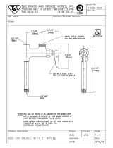
Valve Layout
1" NPT Outlet
1" NPT Inlet
Meter
Cable
1/2" NPT Drain
To Brine Tank
3/8"
Figure 8
Water Line Connection
A bypass valve system is included and will be installed on all
water conditioning systems. Bypass valves isolate the softener
from the water system and allow unconditioned water to be
used. Service or routine maintenance procedures may also
require that the system is bypassed.
IMPORTANT: The bypass valve is shipped to you in the
bypass position. When the valve is in bypass, water will
not enter the softening tank. The water in the building
will not be treated. Figure 9 Series 360 Bypass Operation
shows the handles in the service position.
Once you have selected your location check the direction of
the waterow in the main pipe. Figure 7 Softened Water Flow
Diagram can be used to plan the new plumbing assembly.
Inspect the main water pipe. Write down the type of pipe
(copper, plastic, galvanized etc.). Record the size of the pipe.
Plastic style pipes usually have the size printed on the outside.
Other pipes can be measured for the outside diameter and
converted into the pipe size at the store. Do not use pipe that is
smaller than the main water pipe.
The bypass requires two connector ttings that connect to
the plumbing. Size to be determined for specic installation
requirements.
If the main plumbing is galvanized pipe and you are installing
copper pipe, then you must use dielectric insulating connectors
between the two styles of pipe.
Place the tank in position. The design of the tank does not
allow for bad alignment of the connections. You may ask your
supply store about exable connections.
Take measurements and create a drawing of your installation.
Include pipe lengths and elbows that are needed. If the water
ow is from right to left you will need to cross the plumbing to
the softener. Take the drawing to your plumbing supply store.
Consult with their expert for installation ideas and suggestions.
Assemble the plumbing.
WARNING:
If pipes will be sweat soldered, do not
connect adapters to the bypass until the
pipes have cooled.
IN OUT
IN OUT
Connector
Assembly
“H” Clip
Drain
Line
Handles in Service Handles in Bypass
Figure 9 Series 360 Bypass Operation
WARNING:
The inlet water must be connected to the
inlet port of the valve. When replacing
an exsisting system, it is possible that
the inlet and outlet plumbing is installed
in a reverse position. Be certain the inlet
connection on the valve is connected to the
incoming water tting from the water supply.
WARNING:
Do not use petroleum grease on gaskets
when connecting bypass plumbing. Use
only 100% silicone grease products when
installing any plastic valve. Non-silicone
grease may cause plastic components to fail
over time.
The bypass assembly connects to the water system by means
of a connector assembly. The connector is secured to the
plumbing and then inserted into the bypass. A clip is used to
hold it in place.
Figure 10 Connector Assembly
Before inserting the connector:
• Check that all O-rings are in place and not damaged.
• Lubricate O-rings and sliding surfaces with 100% silicone.
Firmly insert connector into bypass. Press locking clip into
position. Make certain the clip is fully engaged.
EQUIPMENT INSTALLATION continued
6 • MR12 Premier AF-40K

To remove a clip:
1. Turn off water and release water pressure at the valve.
2. Push the water line connectors into the bypass and valve.
This will help release O-rings that may have seated in
place.
3. Remove the clip by inserting a at blade under the top
center of the clip and lifting (prying up).
CAUTION
Do not use pliers to remove a clip. It is likely the
clip will break.
NOTE: Before turning on the water to the valve, rotate the
two handles on the bypass valve 2-3 times. This
will help seat O-rings and prevent leaking.
Drain Line Flow Control
The drain line ow control (DLFC) 1/2" NPT requires assembly
(Figure 11).
1. Locate parts and a roll of plumber tape (not included).
2. Wrap the tape over threads of the ow control.
3. Screw the ow control and a proper size drain tting
together. Hand tighten.
4. Place the ball into the ow control and insert the assembly
into the drain line opening.
5. Push the assembly in and secure with the drain line clip.
Drain Fitting
Flow Control
Control Ball
Drain Line Clip
Figure 11
Drain Line Connection
NOTE: Standard commercial practices are expressed here.
Local codes may require changes to the following
suggestions. Check with local authorities before
installing a system.
1. The unit should be above and not more than 20 feet
(6.1 m) from the drain. Use an appropriate adapter tting
with a hose clamp to connect 1/2-inch (1.3 cm) plastic
tubing to the drain line connection of the control valve.
2. If the backwash ow rate exceeds 5 gpm (18.9 Lpm) or if
the unit is located 20-40 feet (6.1-12.2 m) from drain, use
3/4-inch (1.9 cm) tubing. Use appropriate ttings to connect
the 3/4-inch tubing to the 3/4-inch NPT drain connection
on valve.
3. The drain line may be elevated up to 6 feet (1.8 m)
providing the run does not exceed 15 feet (4.6 m) and
water pressure at the softener is not less than 40 psi
(2.76 bar). Elevation can increase by 2 feet (61 cm) for
each additional 10 psi (.69 bar) of water pressure at the
drain connector.
4. Where the drain line is elevated but empties into a drain
below the level of the control valve, form a 7 inch (18 cm)
loop at the far end of the line so that the bottom of the loop
is level with the drain line connection. This will provide an
adequate siphon trap.
Where the drain empties into an overhead sewer line, a sink-
type trap must be used.
Secure the end of the drain line to prevent it from moving.
Right Way
Figure 12 Drain Line Connection
NOTE:
Waste connections or drain outlet shall be
designed and constructed to provide for
connection to the sanitary waste system through
an air-gap of 2 pipe diameters or
1 inch (22 mm) whichever is larger.
WARNING:
Never insert drain line directly into a
drain, sewer line, or trap (Figure 12 Drain
Line Connection). Always allow an air gap
between the drain line and the wastewater
to prevent the possibility of sewage being
back-siphoned into the softener.
Overow Line Connection
In the event of a malfunction, the salt TANK OVERFLOW will
direct “overow” to the drain instead of spilling on the oor. This
tting should be on the side of the cabinet.
Attach length of 1/2-inch (1.3-cm) I.D. tubing (not supplied) to
tting and run to drain. Do not elevate overow line higher than
overow tting (Figure 13 Overow Line Connection).
Do not tie into drain line of control unit. Overow line must be a
direct, separate line from overow tting to drain, sewer or tub.
Allow an air gap as per drain line instructions.
Figure 13 Overow Line Connection
EQUIPMENT INSTALLATION continued
Premier AF-40K MR12 • 7

Salt Line Connection
The salt line from the brine tube connects to the valve. Make
certain all tting connections are hand tightened. Be sure that
the salt line is secure and free from air leaks. Even a small leak
may cause the salt line to drain out, and the softener will not
draw salt from the tank. This may also introduce air into the
valve causing problems with valve operation.
Brine Tube
Salt Line Connection
Figure 14 Salt Tank Check Valve and Brine Well Assembly
Electrical Connection
CAUTION
This valve and control are for dry location use
only unless used with a Listed Class 2 power
supply suitable for outdoor use.
All Premier Series controllers operate on 12-volt alternating
current power supply. This requires use of the proper supplied
AC adapter included with your system.
AC Adapters:
Make sure power source matches the rating printed on the AC
adapter.
NOTE: The power source should be constant. Be certain
the AC adapter is not on a switched outlet. Power
interruptions longer than 8 hours may cause the
controller to lose the time setting. When power is
restored, the time setting must then be re-entered.
SYSTEM DISINFECTION
Disinfection Of Water Softeners
The materials of construction of the modern water softener
will not support bacterial growth, nor will these materials
contaminate a water supply. During normal use, a softener
may become fouled with organic matter, or in some cases with
bacteria from the water supply. This may result in an off-taste
or odor in the water.
Some softeners may need to be disinfected after installation
and some softeners will require periodic disinfection during
their normal life.
Depending upon the conditions of use, the style of softener, the
type of ion exchanger, and the disinfectant available, a choice
can be made among the following methods.
Sodium or Calcium Hypochlorite
Application
These materials are satisfactory for use with polystyrene
resins, synthetic gel zeolite, greensand and bentonites.
5.25% Sodium Hypochlorite
These solutions are available under trade names such as
Clorox*. If stronger solutions are used, such as those sold for
commercial laundries, adjust the dosage accordingly.
1. Dosage
A. Polystyrene resin; 1.2 uid ounce per cubic foot (35.5 ml
per 0.03 cubic meter).
B. Non-resinous exchangers; 0.8 uid ounce per cubic foot
(23.7 ml per 0.03 cubic meter).
2. Salt tank softeners
A. Backwash the softener and add the required amount of
hypochlorite solution to the well of the salt tank. The salt
tank should have water in it to permit the solution to be
carried into the softener.
B. Proceed with the normal recharge.
*Clorox is a trademark of the Clorox Company.
Calcium Hypochlorite
Calcium hypochlorite, 70% available chlorine, is available
in several forms including tablets and granules. These solid
materials may be used directly without dissolving before use.
1. Dosage
A. 129.5 mg, approximately 0.1 ounce per cubic foot
(3 ml per 0.03 cubic meter).
2. Salt tank softeners
A. Backwash the softener and add the required amount
of hypochlorite to the well of the salt tank. The salt tank
should have water in it to permit the chlorine solution to
be carried into the softener.
B. Proceed with the normal recharge.
EQUIPMENT INSTALLATION continued
8 • MR12 Premier AF-40K

GENERAL PREMIER SERIES
INSTRUCTIONS
Premier Series Controller
Power Loss Memory Retention
The Premier Series controllers feature battery-free time and
date retention during the loss of power. This is designed to
last a minimum of 8 hours depending on the installation.
The controller will continue to keep time and day in dynamic
memory while there is no AC power.
The controller will not track water usage in the event of a
power failure.
All programmed parameters are stored in the Premier Series
static memory and will not be lost in the event of a power
failure. These settings are maintained separately from the time
and day settings.
Motor
The Premier series controller uses a standard 12-volt AC
50/60 Hz motor.
Power
Premier Series controller is available in 50/60 Hz power
conguration:
Information entered or calculated by the controller is stored in
two different ways.
1. A static memory will store:
User programmed values
Salt setting (salt setting)
Hardness setting
Daily averages (history values)
2. A dynamic memory with 8 hour retention will store:
Time of day
Todays water used
Variable Reserve Function
The Premier Series metered-demand volumetric controller
is designed to have a variable reserve feature. This feature
automatically adjusts the reserve to the end-user’s water
usage schedule.
A variable reserve saves salt and water by only regenerating
when absolutely necessary, and ensures enough soft water for
typical high-water usage days.
Each day the controller reviews the last four weeks of water
usage for the same day of the week to determine if the
remaining capacity is adequate for the next day of the week.
If the remaining capacity is not adequate, it will initiate an
automatic recharge.
NOTE: Water ow to the valve can be turned on or
bypassed when the controller is powered up for the
rst time.
DISPLAY ICONS PREMIER
CONTROLLER
MIN
x2
X100
1
67
5
3
2
4
8
Figure 15 Display Icons
NOTE: In normal operation and during programming, only
a few of the icons will actually be displayed.
1. Indicate water ow when displayed. Arrows alternate faster
as ow increases.
2. X100 multiplier for large values.
3. When “MIN” is displayed, the value is in minute increments.
“MIN” is displayed during recharge, the value displayed is
the minutes of recharge remaining.
4. Colon ashes as part of the time display. Indicates normal
operation.
5. Four digits used to display the time or program value. Also
used for error codes.
6. The recycle sign is displayed (ashing) when a recharge
at the next time of recharge has been called for. Also
displayed (continuous) when in recharge.
7. When “x2” is displayed, a second recharge has been called
for.
8. The hourglass is displayed when the motor is running.
NOTE: During normal operation (Service mode) the display
will show the current time of day with the colon
blinking. This will alternate with a display of the
gallons remaining to be treated before recharge.
Premier AF-40K MR12 • 9

KEYPAD - BUTTONS
4
32
1
Figure 16 Keypad Buttons
1. Time of Day - Press and release to display the time of day
for ve seconds. Press button again while current time is
displayed to increment the time 1 minute. Press and hold
for two seconds to rapidly increment the time.
2. Salt Amount - Press and release to display the current
salt setting for ve seconds. There are three salt settings;
HC (High Capacity), Sd (standard capacity) and HE (High
Efciency). Press the button again while the salt setting is
displayed to change the setting.
HC: This setting maximizes the system capacity between
recharges and will also use the most salt. This setting can
be used if you have high water hardness or high water
usage.
Sd: This setting uses moderate amount of salt and provides
a medium amount of water between recharges. This setting
can be used for moderate water hardness or water usage.
HE: This setting minimizes salt usage for a recharge (uses
the least amount of salt) and provides the least amount of
water between recharges. This setting can be used if you
have low water hardness or low water usage.
3. Water Hardness - Press and release to display the current
hardness setting for ve seconds. Press button again while
current setting is displayed to increment the hardness by
one. Press and hold for two seconds to rapidly increment
the hardness setting.
A hardness setting too high will cause the system to
recharge more often and use more salt and water than
what is needed to condition your water.
A hardness setting too low will cause the system to
recharge less often. The system may pass hard water
shortly before it recharges.
4. Recharge - Press and release to initiate a recharge. A
recharge will start at the next scheduled time of recharge
(00:00). A ashing regen symbol will be displayed. To stop
a manual recharge press and release the recharge button
a second time. To start an immediate recharge, press and
hold the recharge button for three seconds. A solid regen
symbol will be displayed. The time display will show the
amount of time left in the recharge cycle.
During a recharge cycle (the recharge icon is on steady), a
second manual (delayed) recharge may be called for. Press
the recharge button and release. To stop a second manual
recharge press and release the recharge button a second
time.
During a recharge cycle (the regen icon on steady), a
second manual (immediate) recharge may be called for.
Press the recharge button a second time for three seconds.
A second immediate recharge can not be stopped.
NOTE: If a button is not pushed for ve seconds, the
controller returns to normal operation mode.
Pushing the recharge button immediately returns
the controller to normal operation.
RECHARGE
During a Recharge:
• Total regen time remaining is displayed on screen.
• The recharge icon is on steady.
MIN
Recharge Total recharge time remaining
Flashes when motor is running
Figure 17 Display during recharge.
To Advance Recharge Cycles:
• Simultaneously press Time of Day and Recharge to
advance to the next cycle. An hourglass will display while
cam is advancing.
When cam reaches the next cycle, Time Remaining will
be displayed.
• Repeat pressing Time of Day and Recharge to advance
through each cycle.
• To determine which cycle the controller is in during a
recharge, use Table 2. The time remaining is displayed
on the controller. Find the time remaining below your salt
setting. The cycle column will have the cycle number.
• Press and hold Time of Day and Recharge for 3 seconds
to advance through all remaining recharge cycles.
Hourglass will ash.
Camshaft will advance to service - may take 1 to
2 minutes.
Recharge Cycles:
Table 1 Length of Cycle
Cycle Cycle Description HE Setting Sd Setting HC Setting
1 Rell 4.1 min 13.0 min 20.1 min
2 Brine Prep 120 min 120 min 120 min
3 Backwash 1 8 min 8 min 8 min
4* Brine Draw 8 min 24 min 36 min
5* Slow Rinse 43 min 43 min 43 min
6 Re-Pressurize 3 min 3 min 3 min
7 Fast Rinse 1 3 min 3 min 3 min
8 Backwash 2 1 min 1 min 1 min
9 Fast Rinse 2 1 min 1 min 1 min
Table 2 Time remaining to end of cycle
Cycle Cycle Description HE Setting Sd Setting HC Setting
1 Rell 193.1 min 205.0 min 237.1 min
2 Brine Prep 189 min 192 min 217 min
3 Backwash 1 69 min 72 min 97 min
4* Brine Draw 61 min 64 min 89 min
5* Slow Rinse 53 min 53 min 53 min
6 Re-Pressurize 10 min 10 min 10 min
7 Fast Rinse 1 7 min 7 min 7 min
8 Backwash 2 4 min 4 min 4 min
9 Fast Rinse 2 3 min 3 min 3 min
*The camshaft does not move between cycles 4 and 5. Cycle 5 begins
when the brine in the salt tank runs out and the check valve closes.
10 • MR12 Premier AF-40K

Recharge Cycle Requirements:
HE Sd HC
Salt/Recharge
(lbs)
4.1 13.0 20.1
Regeneration
Time (Min)
71 96 115
Water to Drain
(gal)
48.2 55.4 59.7
Max. Flow to
Drain (gpm)
2.7 2.7 2.7
PREMIER SERIES INITIAL POWER-UP
The water supply valve should be off or the valve is in by-pass
Initial Power-Up - (Camshaft proceeds to HOME position)
• At initial power-up, the camshaft may need to rotate to the
HOME (in service) position.
• Camshaft may take 1 to 2 minutes to return to HOME
position.
• Err 3 will be displayed until the camshaft returns to HOME
position (Figure 18 Initial Power-Up Display).
• If more than 2 minutes elapses, verify that the motor
is turning the camshaft. If it is not turning, check the
“Troubleshooting” section.
Figure 18 Initial Power-Up Display
When the camshaft has reached the HOME (service) position
the display will show “- -:- -”.
If the time of day alternating with capacity remaining is
displayed then the controller has used short term memory
to load settings. Short term memory will hold settings for
approximately eight hours. Settings include:
• Water used today
• Water used since last recharge
• Current time of day
• Recharge state
Un-programmed controls will have the following settings.
Default settings:
• Hardness - 25 grains per gallon
• Salt setting - HE, High efciency
• System will recharge every 15 days (calendar override)
even if no water is used. Unplug system for long
periods of no water usage. Calendar override is not
programmable.
In addition:
• Water used is set to 0
• The internal system clock is set to 8:00 AM. The display
continues to show “- -:- -” until the time is manually set
which updates the internal clock.
• A recharge will initiate when the internal system clock
reaches 12:00 am. The regen icon will ash.
RECHARGE continued INITIAL START-UP INSTRUCTIONS
1. Set time of day - Press the Time of Day button. Press it
again within 5 seconds and the time will increment. Press
and hold for 2 seconds to rapidly increment the setting.
Release the button and the time will be saved after
5 seconds.
Figure 19 Step 1
2. Pick the salt setting - The controller starts (defaults) with
the HE (high efciency) setting. If you want to check or
change the setting, press the Salt Amount button to display
the current setting. To change it, press the Salt Amount
button again within 5 seconds. The new setting will be
saved after 5 seconds.
HC: This setting maximizes the system capacity between
recharges and will also use the most salt. This setting can be
used if you have high water hardness or high water usage.
Example: 3 or more people and/or hardness above 25 gpg.
Sd: This setting will provide a mid-range capacity. Less
salt is used than the HC (High Capacity), setting. More
water between recharges is provided than when the HE
(High Efciency) setting is used. Use this setting if the
conditioner is running out of capacity when set to HE. This
setting is also used if the HC setting is providing too much
capacity. Use this setting if your usage or water hardness
fall between the HC and HE examples.
HE: This setting minimizes salt used for a recharge (uses
the least amount of salt) and provides the least amount of
water between recharges. This setting can be used if you
have low water hardness or low water usage. Example: 2
or less people and/or hardness below 20 gpg.
Figure 20 Step 2
Premier AF-40K MR12 • 11

3. Enter the hardness of the water - The controller starts
(defaults) at a hardness of 25 gpg. Check your water for
the actual hardness. Press the Water Hardness button to
display the current settings. To change the setting press
the button again within 5 seconds. To rapidly increase the
setting push and hold the Water Hardness button. Release
the button and the setting will be saved after 5 seconds. A
hardness setting too high will cause the system to recharge
more often and use more salt and water than what is
needed to soften your water. A hardness setting too low will
cause the system to recharge less often. The system may
pass hard water shortly before it recharges.
Figure 21 Step 3
Programming is complete. The controller will begin normal
operation if no button is pushed for 5 seconds.
During normal operation (Service mode) the display will
show the current time of day with the colon blinking. This will
alternate with a display of the gallons remaining to be treated
before recharge.
RECHARGE continued PLACING SOFTENER INTO OPERATION
After you have performed the previous initial power-up steps,
you will need to place the softener into operation. Follow these
steps carefully.
WARNING:
If the inlet water valve is opened too rapidly
or too far, media may be lost out of the tank
into the valve or the plumbing. In the 1/4
open position, you should hear air slowly
escaping from the valve drain line.
NOTE: We recommend that you do not put salt into the
tank until after the control valve has been put into
operation. With no salt in the tank, it is much easier
to view water ow and motion in the tank.
NOTE: As you advance through each cycle there will
be a slight delay before you can advance to the
next cycle. The hourglass icon will light while the
camshaft is indexing.
Press and hold the Recharge key to start a recharge.
To Advance Recharge Cycles:
• Simultaneously press Time of Day and Recharge to
advance to the next cycle. An hourglass will display while
cam is advancing.
When Cam reaches the next cycle, Time Remaining will
be displayed.
• Repeat pressing Time of Day and Recharge to advance
through each cycle.
• To determine which cycle the controller is in during a
recharge, use Table 1. The time remaining is displayed
on the controller. Find the time remaining below your salt
setting. The cycle column will have the cycle number.
• Press and hold Time of Day and Recharge for 3 seconds
to advance through all remaining recharge cycles.
Hourglass will ash.
Camshaft will advance to service - may take 1 to
2 minutes.
• For cycle times see Table 1.
Before turning on the water supply check the following:
• All plumbing is installed and secured.
• The valve drain line is in place and the end is held
securely at the drain.
• There is no salt in the tank.
• The controller is on and has been programmed following
the three steps. The display should be showing the time
of day with the colon ashing.
• The inlet water is off and the bypass is not in bypass
Both valve
handles pointing
in direction of
water flow
If any of the above are not true please correct the item before
proceeding further.
12 • MR12 Premier AF-40K

The following steps will describe how to perform a quick
recharge to verify the system is working correctly.
1. Turn the incoming water on at a low ow position. Listen
to the water ow. Water is entering the media tank. Do not
open the valve completely because media may enter the
valve.
2. Start a recharge.
3. Open a service faucet. The salt tank will begin to ll with
water. Air will come out of the faucet. After all of the air has
left the media tank the water will run without air spurts.
When the salt tank has 3 to 4 inches (7.6 or 10.1 cm) of
water, turn off the faucet and advance to the next cycle.
4. Turn inlet water on full.
5. The brine prep cycle allows the water in the salt tank to
dissolve the salt. During this cycle inspect for leaks. If
any leaks are present they should be repaired before
proceeding. If there are no leaks, advance to the next cycle.
6. Backwash forces water through the media to the drain.
Inspect the water for air bubbles and small particles. When
the water is running clear, advance to the next cycle.
7. Brine draw and slow rinse run at the same time. The
discharge to drain will slow down. The water in the salt tank
will lower. If water is leaving the salt tank, advance to the
next cycle.
8. The repressurize cycle is short and allows internal system
pressures to stabilize. After 1-2 minutes advance to the
next cycle.
9. Fast rinse is a full pressure rinse of the media in the tank.
The discharge to drain should be high. Advance to the next
cycle.
10. Backwash 2 is a second backwashing of the media tank.
Discharge to drain will be slow. Advance to the next cycle.
11. Fast rinse 2 is the last cycle in the recharge process. Flow
to drain will be high. This cycle is 1 min long. Allow this
cycle to complete and advance to Service.
The controller will start the rst time with a recharge scheduled
to start at the normal time of recharge. The media in the tank
will function properly until that rst recharge.
Fill the salt tank with softener salt. The display should be
showing the current time of day and the colon will be ashing.
The system is fully operational.
During normal operation (Service mode) the display will
show the current time of day with the colon blinking. This will
alternate with a display of the capacity remaining.
PLACING SOFTENER INTO OPERATION
continued
PLACING SOFTENER INTO OPERATION
(TURNING ON THE WATER)
Things You Might Need to Know
• When the controller is rst plugged in, it may display a
ashing hourglass and the message Err 3, this means
that the controller is rotating the camshaft to the home
position.
• The preset default time of recharge is 12:00 am.
• The Premier Series controller is programmed to recharge
if a recharge has not taken place in the last 15 days. This
setting cannot be changed.
• Make sure control power source is plugged in. The
transformer should be connected to a non-switched
power source.
• Unless changed, the settings for a newly installed system
are:
Hardness - 25 gpg
Salt Setting - HE (High Efciency)
Water Used Settings - 0 cubic meters
Internal System clock is set to 8:00 am. The display
continues to show “- -:- -” until the time is manually set.
The rst recharge will occur when the system clock
reaches 12:00 am.
Accessing History Values
The Premier control features a review level that displays the
operation history of the system. This is a great troubleshooting
tool for the control valve.
To access history values, press Recharge followed by the Salt
Amount button and hold for 3 seconds to view the Diagnostic
Codes.
NOTE: If a button is not pushed for 30 seconds the
controller will exit the history table.
Press the Time of Day button to increment through the table.
When the desired code is reached, Press the Salt Amount
button to display the value.
When the Salt Amount button is pressed to view H2 the current
ow rate will be displayed but not updated. Continue to press
and release the Salt Amount button every 5 seconds to update
the display. The ow icons on the display will ash when there
is ow thru the softener.
Code Description Notes
H1 Days since last recharge Days since last recharge
H2 Current ow rate Liters per minute
H3 Current day of week Current day of week
H4 Water used today since 0200
In cubic meters,
max value displayed 99.99
max value stored 655.35
H5 Water used since last recharge
A0 Average water usage for day 0
A1 Average water usage for day 1
A2 Average water usage for day 2
A3 Average water usage for day 3
A4 Average water usage for day 4
A5 Average water usage for day 5
A6 Average water usage for day 6
Premier AF-40K MR12 • 13

Item No. QTY Part No. Description
1 ............. 1 .......367023...........Tank Brine
2 ............. 1 .......213126...........Housing
3 ............. 1 .......313012...........Lid
4 ............. 1 .......367202...........Latch
5 ............. 1 .......167028...........Controller, AF-40K
6 ............. 1 .......367026...........Resin Tank
7 ............. 1 .......367203...........Brine Tube Assembly
8 ............. 1 .......249033...........Clamp, Resin Tank
9 ............. 1 .......249035...........Clamp, Float Tube
10 ........... 1 .......116181 ...........Valve Assembly w/Bypass
and Connectors
11 ...........6 .......246068...........Housing Mounting Screws
12 ........... 1 .......367204...........Lower Distributor Assembly
10x35 Tank
13 ........... 1 .......367205...........Upper Basket
14 ........... 1 .......367206...........Conditioning Resin
15 ........... 1 .......367207...........Retainer, Brine Tank
5
8
9
7
6
10
1
4
3
2
11
12
13
14
TANK ASSEMBLY
15
14 • MR12 Premier AF-40K

5
8
9
7
6
10
1
4
3
2
22
21
20
19
18
17
16
15
14
13
12
11
Item No. QTY Part No. Description
1 ............. 1 .......367208...........Assembly, Premier Controller
Cover
2 ............. 1 .......116182 ...........Valve Body Assy, Volumetric
Includes Item #18
3 ............. 1 .......367209...........Valve Disc Kit
4 ............. 1 .......367210...........Top Plate
5 ............. 1 .......125139...........Female Elbow, 3/8 NPT to
3/8 Tubing
6 ............ 12 ......146034...........Screw, Top Plate
7 ............. 1 .......367211 ...........Spring, Top Plate
8 ............. 1 .......367212...........Camshaft, Rell First
9 ............. 1 .......367213...........Yoke, Camshaft
10 ........... 2 .......146036...........Screw, Yoke
11 ...........1 .......270341...........368 Valve Motor/Optical
Sensor Assy
12 ........... 1 .......367214...........Injector Cap Assembly
13 ........... 1 .......367215...........“J” Injector, Lt Blue, 10 Inch
Tank
1 .......367216...........Screen
1 .......367217...........“J” Injector w/O-rings
14 ........... 1 .......622013...........Assembly, Rell Cont, .33
gpm
15 ........... 2 .......622014...........Ball, Backwash, Brine Rell
Controller
16 ........... 1 .......252229...........O-ring, Tank
17 ........... 1 .......252230...........O-ring, Riser
18 ........... 1 .......367218...........Meter Assembly
19 ........... 1 .......258261...........Assembly, Sensor Cable
20 ........... 1 .......252231...........Kit, O-ring, Manifold
21 ........... 1 .......116183 ...........Bypass
1 .......367224...........Main Assembly
2 .......367219...........Retainer, Manifold
2 .......228305...........Clips Retainer
1 .......252232...........Kit, O-ring Manifold
22 ........... 1 .......622015...........Kit, Drain Line Flow Control
1 .......622016...........Flow Control w/O-ring and
Clip Drain Line and Ball
23 ........... 1 .......258100...........120 VAC, 60 Hz, N. America
Plug
24 ........... 2 .......125154...........Connector Assembly, 1" NPT,
Plastic, w/O-ring and Clip
Retainer
25 ........... 1 .......125155...........Fitting, Drain Line, 90°, 1/2"
NPT, 1/2" Tube
Item No. QTY Part No. Description
VALVE ASSEMBLY
23
24
25
Premier AF-40K MR12 • 15

BRINE WELL ASSEMBLY CH20795
Item No. QTY Part No. Description
1 ............. 1 .......367220...........Brine Well w/Slots
2 ............. 1 .......116184 ...........Safety Brine Valve
3 ............. 2 .......228306...........Grommet
4 ............. 1 .......400080...........Tubing, 3/8" x 16" Long
5 ............. 1 .......367221...........Cap, Brine Well 4" Dia.
(Caplug STP-4)
6 ............. 1 .......367222...........Brine Float w/One Grommet
(As purchased)
7 ............. 1 .......367223...........Air Check Assembly
8 ............. 2 .......231049...........Tubing Insert, Brass
Not Shown
1 .......231056...........Overow Fitting Assembly
1 .......*231057 .........Overow Elbow
1 .......*231058 .........Overow Nut
1 .......*252234 .........Gasket
*Parts included with CH20774 Overow Fitting Assembly
5
8
7
6
1
4
3
2
8
16 • MR12 Premier AF-40K

TROUBLESHOOTING
Premier Control - Error Codes
Problem Possible Cause Solution
Err 1 is displayed. Program settings have been corrupted. Press any key. If Err 1 does not clear, replace control.
Err 3 is displayed. Control does not detect the camshaft position and is
returning to the service position.
Wait until the control returns to the service position. Flashing
hourglass in the display indicates that the motor is running
Camshaft is not turning during Err 3 display. Check that motor is connected. Verify that the motor wire
harness is connected to motor and controller module. Verify
that optical sensor is connected and in place. Verify that
motor gear has engaged the camshaft.
If everything is connected, replace components in this order:
1. Motor Assembly, Optical Sensor
2. Control
Camshaft is turning more than ve minutes to nd the
service position:
Verify that optical sensor is in place and connected to wire.
Inspect for debris in the camshaft slots.
If motor continues to rotate indenitely, replace the following
components in this order:
1. Optical Sensor
2. Control
System
Problem Possible Cause Solution
Salt tank overow. Loose salt line connection. Ensure all salt line connections are tight.
Drain line restricted with debris. Clean drain control.
Flowing or dripping water at drain or salt line
after recharge.
Debris is preventing #4 valve disc from closing
(Figure 23 Valve Layout).
Remove debris.
Worn #4 valve disc (Figure 23 Valve Layout). Replace valve discs.
Hard water leakage after recharge. Improper recharge. Repeat recharge after making certain correct
salt dosage was set.
Leaking of external bypass valve. Replace bypass valve.
O-Ring around riser pipe damaged. Replace O-ring.
Valve will not draw brine. Restricted drain line. Remove restriction.
Injector plugged. Clean injector and screen.
Debris is preventing valve discs from closing. Remove foreign matter from valve discs.
Control will not recharge automatically. AC adapter or motor not connected. Connect power.
Defective motor. Replace motor.
Meter clogged with debris. Unit will recharge
every 7 days anyway.
Remove and clean meter.
Control recharges at wrong time of day. Time of Day set incorrectly. Set the correct Time of Day.
Intermittent salt draw. Low water pressure. Maintain a minimum of 20 psi
(1.3 bar) feed.
No conditioned water after recharge. No salt in salt tank. Add salt to salt tank.
Injector plugged. Clean injector and screen.
Backwashes or rinses at excessively low or
high rate.
No drain line ow control. Install drain line ow control.
Restricted drain line. Remove restriction.
Runs out of conditioned water between
recharges.
Control improperly programmed. Verify salt dosage.
Flow indicator on control does not display
service ow.
Bypass valve in bypass position. Remove bypass valve from bypass.
Meter cable dislodged from valve. Fully insert meter cable into valve.
Meter clogged with debris. Remove and clean meter.
Premier AF-40K MR12 • 17

Valve Disc Operation
When the Premier control is lifted up (Figure 22 Control
Removed) and the cover is removed, the appers and
camshaft are visible (Figure 23 Valve Layout).
Figure 22 Control Removed
Injector Cap
Rell
Control Cap
Figure 23 Valve Layout
TROUBLESHOOTING continued
18 • MR12 Premier AF-40K

PREMIER LIMITED WARRANTY
Water Softener
Premier warrants to the original owner, that under normal use: Fiberglass mineral tanks and brine tanks for water softeners will be
free from material defects in materials and workmanship for ten (10) years from the date of purchase. The control valve electronic
controller, valve bodies and internal valve parts (not including brine injectors) for water softeners will be free from material defects
in materials and workmanship for ve (5) years from the date of purchase. Additional parts for water softeners not mentioned
above will be free from material defects in materials and workmanship for two (2) years from the date of purchase. Any replace-
ment products furnished will be free from material defects in materials and workmanship for the remainder of the original warranty
period.
This warranty does not cover: (1) water softening resin (2) damage due to lightning or other conditions beyond the control of
Premier (3) defects not reported within the above-stated time periods, (4) items manufactured by other companies, (5) problems
arising from failure to comply with Premier instructions, (6) problems or damage arising from acts of nature, abuse, misuse, negli-
gence or accident (7) problems or damage resulting in whole or in part from alteration, modication, repair or attempted alteration,
modication or repair by any party other than Premier or a Premier authorized dealer (8) noncompliance with applicable codes/
ordinances.
If a defect in workmanship or materials in a product or part covered by the warranty should arise, Premier at its sole discretion, will
repair or replace the defective product or part.
For warranty service, when in Canada call (905) 332 4090, in US call (800) 752-5582 or (480) 675-7995 for documentation and
a return authorization number. All claimed defective product or parts must: (1) be authorized for return by Premier with a Return
Goods Authorization number (2) include proof of the purchase date of the product or part (3) be returned to Premier prior to the
expiration of the applicable warranty period, at the customer's expense, shipment pre-paid, (4) be accompanied by a letter detailing
the problem experienced. Include your name, address and your return authorization number, model number and serial number of
the system.
TO THE MAXIMUM EXTENT PERMITTED BY APPLICABLE LAW, PREMIER DISCLAIMS ALL OTHER WARRANTIES, WHETH-
ER EXPRESS OR IMPLIED, INCLUDING, BUT NOT LIMITED TO, THE IMPLIED WARRANTIES OF MERCHANTABILITY AND
FITNESS FOR A PARTICULAR PURPOSE, WITH REGARD TO THE PRODUCTS, PARTS AND ANY ACCOMPANYING WRIT-
TEN MATERIALS.
To the maximum extent permitted by applicable law, Premier shall not be liable for any damages whatsoever (including, but not
limited to, loss of time, inconvenience, expenses, labor or material charges incurred in connection with the removal or replacement
of the product or part, special, incidental, consequential, or indirect damages for personal injury, loss of business prots, business
interruption, loss of business information, or any other pecuniary loss) arising out of the use of or inability to use the defective prod-
ucts or parts, even if Premier has been advised of the possibility of such damages.
Premier’s maximum liability under any provision of this Limited Warranty shall be limited to the amount actually paid for the product
or part.
NOTE: Because some states do not allow the exclusion or limitation of incidental or consequential damages, the above limitations
or exclusions may not apply.
This warranty does not cover any equipment that is relocated from the site of its original installation.
This warranty does not cover any equipment that is installed or used outside the United States of America and Canada.
THIS WARRANTY GRANTS SPECIFIC LEGAL RIGHTS, AND OTHER RIGHTS MAY APPLY. SUCH RIGHTS VARY FROM
STATE TO STATE.
7-2010
Warranty Registration
Register by phone, fax, mail or online.
Call: 1-800-752-5582
Fax: 1-623-866-5666
Online: www.wattspremier.com
Mail: Watts Premier, Inc.
8716 W. Ludlow Drive Suite #1
Peoria, AZ 85381
Premier AF-40K MR12 • 19

©2012 Premier • Printed in U.S.A. 167041 Rev B MR12
PERFORMANCE DATA SHEET
Model Premier AF-40K
Rated Service Flow (gpm) 11.0
Pressure Drop at Rated
Service Flow Rate (psid)
15.0
Rated Capacity
(grains @ lb of salt)
18,143 @ 4.12
33,809 @ 12.97
41,386 @ 20.0
Rated Efficiency
(grains/lb Salt @ lb of salt)
4,400 gr/lb. salt @ 4.12 lbs.
Maximum Flow Rate During
Regeneration (gpm)
2.7
Indion 225 NaF
Ion Exchange Resin (cu ft)
1.25
Tank size 10" x 35"
Backwash - GPM 2.7
Rapid Rinse/purge - GPM 2.7
Operating Pressure: 20 -125 psi or 1.4 – 8.8 kg/Centimeter
2
, Operating Temperature: 35 - 100° F or 1.7 – 38° C
Acceptable Salt Type: Sodium Chloride – Pellet
All Systems above tested at 35 psi +/- 5 psi, pH of 7.5 +/- 0.5, Capacity Testing Flow Rate = 50% of the rated service flow
rate for the various size systems.
These water softener systems have been tested by WQA and conform to NSF/ANSI 44
for specific performance claims as verified and substantiated by test data. The rated salt
efficiencies above were also determined in accordance with NSF/ANSI 44 and are only valid
at the salt dosage referenced above. An efficiency rated water softener is a demand initiated
regeneration (DIR) softener which also complies with specific performance specifications
intended to minimize the amount of regenerant brine and water used in its operation. Efficiency
rated water softeners shall have a rated salt efficiency of not less that 3350 grains of total
hardness exchanged per pound of salt (based on NaCl equivalency) (477 grams of total
hardness exchanged per kilogram of salt), and shall not deliver more salt than its listed rating.
The rated efficiency of the water softener, the salt dosage at that efficiency, the capacity at
that salt dosage and that of the efficiency is only valid at the stated salt dosage. Efficiency is
measured by a laboratory test described in NSF/ANSI 44. The test represents the maximum
possible efficiency the system can achieve. Operational efficiency is the actual efficiency
achieved after the system has been installed. It is typically less than the efficiency due to
individual application factors including water hardness, water usage, and other contaminants
that reduce the water softener’s capacity. These systems are not intended to be used for
treating water that is microbiologically unsafe or of unknown quality without adequate
disinfection before or after the system. Refer to the system Installation and Service Manuals for
set-up and programming instructions. Contact your local Premier dealer for parts and service.
See your owner’s manual for warranty information.
Important Notice: For conditions of use, health claims certified by the California Department of
Public Health and replacement parts, see product data sheet
Iowa Requirement:
Seller: ________________________________________________ Date: _________________________
Buyer: ________________________________________________ Date: _________________________
12/15/11
T
E
S
T
E
D
A
N
D
C
E
R
T
I
F
I
E
D
U
N
D
E
R
I
N
D
U
S
T
R
Y
S
T
A
N
D
A
R
D
S
Tested and Certified
by the WQA against
NSF/ANSI Standard
44 for Softener
Performance &
NSF/ANSI 372
for “lead free”
compliance.
Premier Inc
8716 W. Ludlow Drive Suite #1
Peoria, Arizona 85381
Phone: (800) 752-5582
www.wattspremier.com
/