Sierra 500-CalTrak User manual
- Category
- Measuring, testing & control
- Type
- User manual

Instruction Manual
Cal=Trak SL-500 Primary Gas Flow Calibrator
Instruction Manual
Revision D4 July 2008

2
Worldwide Locations to Serve You
CORPORATE HEADQUARTERS
5 Harris Court, Building L Monterey, CA, 93940 USA
Phone (831) 373-0200 (800) 866-0200 Fax (831) 373-4402
www.sierrainstruments.com
EUROPE HEADQUARTERS
Bijlmansweid 2, 1934RE Egmond a/d Hoef, The Netherlands
Phone +31 72 5071400 Fax +31 72 5071401
ASIA HEADQUARTERS
Room A618, Tomson Centre
188 Zhang Yang Rd, Pu Dong New District, Shanghai, PR China 200122
Phone + 8621 5879 8521 Fax +8621 5879 8586

3
Table of Contents
0.0 Sierra Instruments Locations 2
1.0 General Description 5
2.0 Theory of Operation 5
3.0 Cal=Trak Layout 7
4.0 Unpacking Checklist 7
5.0 Warnings 8
6.0 Installation 8
6.1 Attaching and Removing Flow Cells 8
6.2 Connecting the Cal=Trak to a Flow Source 8
6.3 The Cal=Trak Measurement Cycle 8
6.4 Application Precautions 10
6.5 Comparison vs. Calibration, the “4 to 1 rule” 10
7.0 Installation Diagrams and Application Guide 11
7.1 Comparison of Cal=Trak with Piston or Bell Provers 11
7.2 Vacuum Comparison of Cal=Trak with Piston or Bell Provers 12
7.3 Comparison of Cal=Trak with Laminar Flow Element Transfer Standards 13
7.4 Comparison of Cal=Trak with Sonic Nozzle Transfer Standards 13
7.5 Vacuum Comparison of Cal=Trak with Sonic Nozzle Transfer Standards 14
7.6 Calibration of Mass Flow Controllers (MFCs) 14
7.7 Calibration of Mass Flow Meters (MFMs) 15
7.8 Calibration of Rotameters (Variable Area Flow Meters) 15
8.0 Operating Instructions 16
8.1 The Cal=Trak Keypad 17
8.2 How to Use the Cal=Trak Keypad 17
8.3 Factory Default Settings 18
8.4 Taking Readings 18
8.5 Setting User Preferences 19
8.6 Setup Menu 1, Calibration ID #, Gas Constant, Calibration Type 19
8.7 Setup Menu 2, Reading Type, # in Average, Minutes/Reading 20
8.8 Setup Menu 3, Temp. Correction Factor, Temp. & Pressure Formats 20
8.9 Setup Menu 4, Date, Time & Battery Voltage 20
8.10 Setup Menu 5, Date & Time Formats 21
8.11 Setup Menu 6, Leakage & LCF (Leakage Correction Factor) 21
9.0 Battery System 22
9.1 Battery Maintenance & Storage 22
10.0 Calibrator Maintenance, Quality Assurance 23
10.1 Leak Test Procedure 23
10.2 Calibration 24
10.3 Returning Your Unit for Calibration or Service 25
10.4 Shipment 25
10.5 Replacement Parts & Accessories 25
10.6 Additional Information 26
11.0 Limited Warranty 27

4
Appendices
A Cal=Trak Trouble Shooting Guide 28
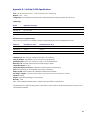
B Cal=Trak Specifications 30
C Cal=Soft Communication Program 31

5
1.0 General Description
The Sierra Cal=Trak is a primary standard piston prover that can be used to measure gas flow rates with high accuracy. It is a
powerful tool for calibration or flow verification because it combines the accuracy of a primary standard with unequaled speed
and convenience.
The Sierra Cal=Trak consists of two primary sections. The base houses the main computer and time base, while the flow cell
utilizes near-frictionless piston technology to perform the actual physical measurements using a precision-machined graphite
composite piston and borosilicate glass tube. The flow cell also contains integrated temperature and barometric pressure
sensors. The base has 9-pin connector and two guide pins on its upper surface into which the interchangeable flow cells are
installed.
Volumetric or Standardized flow readings are obtained with the push of a button. The Cal=Trak can be set to take flow readings
manually, one reading at a time, or automatically, in the auto-read mode. The Cal=Trak can be programmed for up to 100
readings in an averaging sequence.
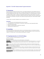
The Cal=Trak includes an RS-232 port for computer interface capability. An application program Cal=Soft communication with
the Cal=Trak is included with your purchase on CD-ROM. Cal=Soft can be used for downloading data from Cal=Trak, creating
Calibration Certificates and as part of an automated calibration system. See Appendix C: Cal=Soft Communication Program at
the end of this Manual.
2.0 Theory of Operation
The Sierra Cal=Trak is a true primary gas standard. The time required for the graphite composite piston to traverse a known
distance through the flow cylinder is precisely measured and an internal computer calculates the flow. The volumetric accuracy
of the instrument is built into its dimensional characteristics. Standardization of the gas flow readings is achieved with precisely
calibrated temperature and pressure sensors.
Piston provers like the Cal=Trak are characterized by the most basic of quantities: length and time. As flow is necessarily a
derived unit, a dimensionally characterized primary system would be as close as possible to direct traceability from national
dimensional standards. This is the inherent benefit of a primary standard.
An idealized piston prover would consist of a massless, frictionless, leakproof, shape-invariant and impermeable piston
inserted within the flow stream and enclosed by a perfect cylinder. The time that the piston takes to move a known distance
(which implies a known volume) then yields the volumetric flow as:
F = V / T =
πr
2
h / T
Such a device would be as accurate as its physical dimensions and its clock, with almost insignificant drift mechanisms.
Although such idealized devices do not exist, we believe the Cal=Trak offers close to ideal performance (Figure 1).
The Cal=Trak clearance-sealed prover uses a piston and cylinder fitted so closely that the viscosity of the gas under test
results in a leakage small enough to be insignificant. For reasonable leakage rates, such a gap must be approximately 10
microns. As a practical matter, the piston and cylinder are made of graphite and borosilicate glass because of their low,
matched temperature coefficients of expansion and low friction.

6
Figure 1 Idealized Automatic Piston Prover
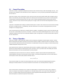
In order to make an intrinsically volumetric device useful for measuring mass, it is necessary to adjust the readings to a
standardized temperature and pressure. For this reason, we include temperature and pressure transducers to allow
computation of standardized (mass) flow by the internal computer (Figure 2).
Bypass Valve
Vent
Temperature
Transducer
Inventory Volume
Inlet Filter
Inlet
Cylinder
Piston
Absolute
Transducer
Light
Emitter
Photodiode
/ Collimator
Figure 2 Practical Piston Prover
Bypass Valve
Vent
Inventory Volume
Inlet Filter
Inlet
Cylinder
Piston
Light
Emitter
Photodiode
/ Collimator

7
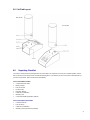
3.0 Cal=Trak Layout
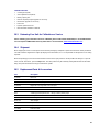
4.0 Unpacking Checklist
Your Sierra Cal=Trak has been packaged with care and includes all components necessary for complete operation. Please
take a moment to check that you have received the following items. If you believe you have not received a full shipment or if
you have any questions, please contact Sierra immediately.
Your Cal=Trak Base Includes
• Cal=Trak Electronic Base
• Battery Charger
• Leak Test Cable
• RS-232 Cable
• Instruction Manual
• Certificate of Calibration
• Warranty Card
• Cal=Soft CD-ROM (Application software)
Your Cal=Trak Flow Cell Includes
• Cal=Trak Flow Cell
• Leak Test Plug
• Certificate of Calibration
• Warranty Card (If purchased separately)

8
5.0 Warnings
The Sierra Cal=Trak is not rated intrinsically safe and is not for use with explosive gasses or for use in explosive
environments.
The Sierra Cal=Trak is not designed for use with a differential pressure above 136 mbar (2 PSI) or for gas flows above the
rated specifications of the flow cell in use. Please consult Chapter 7 and the product specifications in Appendix B for more
information regarding acceptable gas flow ranges or visit our website at www.sierrainstruments.com for the most current
product specifications.
The Sierra Cal=Trak is for use with clean laboratory air or other inert, non-corrosive gases only.
6.0 Cal=Trak Installation
6.1 Attaching & Removing Flow Cells
The Sierra Cal=Trak accepts interchangeable cells for different flow ranges. If user tries to enter “Run Menu” prior to installing
a flow cell, the unit indicates “No Cell” and returns to the “Main Menu” after a 5 second delay.
Attaching Flow Cells
1. Position the selected flow cell into the electronics base opening with its front label facing you.
2. Locate the guide pins; when the guide pins are engaged, press down firmly.
3. When the power is turned on, the Cal=Trak electronics will sense which cell is installed and display the appropriate units
for that cell.
Removing Flow Cells
Grasp the flow cell firmly by the base of the cylinder and lift upward out of the base.
6.2 Connecting the Cal=Trak to a Flow Source
As the accuracy of the Cal=Trak is dependent upon the mechanical set-up (plumbing) of the device under test, it is useful to
review the basic operation of the calibrator prior to plumbing. Always remember the following important guidelines:
1. The accuracy of the Cal=Trak is dependent upon its source being stable. An unstable flow source may produce
inconsistent readings.
2. Sierra Instruments’ Cal=Trak is designed to be used at ambient pressures. Do not subject the Cal=Trak to a
differential pressure above 136 mbar (2 PSI). In other words, the pressure drop across the Cal=Trak calibrator must
not exceed 136 bar (2 PSI). For positive pressure scenarios, this is easily accomplished by leaving the outlet of the
flow cell open to atmosphere. In vacuum scenarios, leave the inlet open to atmosphere. If using a vent line to
remove test gas, make certain that the vent tubing is of sufficient diameter that the pressure across the Cal=Trak
does not exceed 136 mbar (2 PSI) or damage may result.
3. Flow direction is indicated by the arrow on the top of the flow cell. To use a pressure flow source, connect to the inlet
fitting, or to use a vacuum flow source, connect to the outlet fitting.
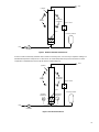
6.3 The Cal=Trak Measurement Cycle
Operation of a Cal=Trak is extraordinarily simple, and little training is required. However, any measurement interacts with the
device being calibrated to some degree. Often, these interactions are negligible. However, sometimes device interactions can
seriously affect measurement accuracy. Here we will explain what happens during a Cal=Trak measurement to aid in installing
and using the instrument appropriately.
In its inactive state, the Cal=Trak will, like any device, exhibit a constant insertion pressure drop. At all but the highest flows, the
pressure drop is very small. In the inactive state, gas flows from the inlet to the outlet through the bypass valve (Figure 3
).
When a measurement cycle begins, the bypass valve closes, and the gas is directed into the cylinder, effectively inserting the

9
piston in series with the gas flow, allowing measurement. Timing commences after the piston has accelerated to the flow
stream’s speed. At the end of the timed cycle, the valve opens and the piston falls to its inactive position at the bottom of the
cylinder.
Bypass Valve
Piston
Inlet
Outlet
Figure 3 Basic Piston Prover
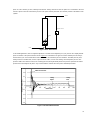
In real-world applications, there are significant dynamics to consider. At the beginning of a cycle, pressure rises rapidly until the
piston accelerates to the speed of the flow stream. Figure 4
is an illustration of a typical Cal=Trak’s internal pressure during a
measurement cycle. A near-maximum flow rate is illustrated to accentuate the pressure variations. The initial pressure pulse,
lasting some tens of milliseconds, reaches a peak of about 0.5 kPa, or 0.5% of its working, near-atmospheric pressure. The
pressure settles out to about 0.1 kPa (0.1% of working pressure) during the timed period. This pressure represents the added
pressure due to the weight of the piston. Very small oscillations continue due to the piston’s underdamped nature.
-0.8
-0.6
-0.4
-0.2
0
0.2
0.4
0.6
0.8
0 100 200 300 400 500 600 700 800 900 1000
Milliseconds
Intracell Pressure (kPa)
Timing
Begins
Timing
Ends
Initial Pressure Pulse
Figure 4 Cal=Trak Internal Pressure

10
6.4 Application Precautions
Although the Cal=Trak’s dynamic pressure effects are very small, in some circumstances they may affect the measurement or
interact with the device under test. For the above reasons, certain precautions should be observed when using a Cal=Trak.
Initial Pressure Pulse
The initial pressure pulse is small, about 1% of an atmosphere or less. However, even so small an increase may affect some
very sensitive transducers for several seconds. Two examples of this are the resonant transducers used in LFE systems such
as the DH Instruments Molbloc or capillary-based systems. For this reason, the LFE instrument may not be accurate for a
number of seconds after the start and the end of a Cal=Trak measurement cycle. When calibrating such systems, a stable flow
source should be used and the LFE read before and after the Cal=Trak cycle.
Intra-Cycle Pressure Change
After the initial brief pressure pulse, the change in insertion pressure is typically 0.1% of an atmosphere (~0.1 kPa or 1 cm
water column). This is usually insignificant. For example, flow from a 100 kPa gauge pressure (15 psi) source will change by
0.1%. However, very low pressure sources will show larger flow change during a Cal=Trak cycle and may require
compensating calculations to achieve Cal=Trak’s best applied accuracy.
Inventory (Dead) Volume
Inventory volume consists of all the space contained between the flow source’s point of restriction and the timed portion of the
cylinder. This includes tubing, empty space within the Cal=Trak base, the lower portion of the measuring cylinder and any other
space contained within the test setup.
It is important to keep inventory volume to a minimum. Excess inventory volume amplifies
the effects of minute pressure
variations within the Cal=Trak cell. In extreme cases, the excess volume also prevents gas pressure from accelerating the
piston properly, causing significant errors in readings. Ideally, the volume contained between the cell and the flow source
should be on the order shown in Table 1
, which also shows the volume as an equivalent length of tubing.
Table 1 Recommended Maximum External Volume and Tubing Lengths
Recommended Maximum Length—meters (inches)
Cell Size
Recommended
Max. Volume (cc)
3mm ID (1/8“) 6mm ID (1/4“) 9mm ID (3/8“)
Small (SL-500-10) 9 1.2 (47.2”) 0.3 (11.8”) N/A
Medium (SL-500-24) 46 6.5 (256”) 1.6 (63.0”) 0.7 (27.6”)
Large (SL-500-44) 118 16.7 (658”) 4.2 (165”) 1.9 (74.8”)
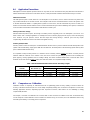
6.5 Comparison vs. Calibration
Calibration consists of comparing an instrument with one of significantly greater accuracy (ideally, at least four times the
accuracy of the device under test (the “4 to 1 rule” widely accepted by industry). We use the term “comparison” in most of the
following applications because, depending upon their respective accuracies, either device can be calibrating (or simply
compared with) the other.
For example, a 0.2% LFE can calibrate a 1% Cal=Trak, while a 0.15% Cal=Trak can calibrate a 0.6% LFE. On the other hand,
a 0.15% lab prover cannot calibrate a 0.15% Cal=Trak to its rated accuracy (or vice-versa). One can calibrate the other to only
0.3% with great certainty, so we simply call it a comparison.

11
7.0 Installation Diagrams and Application Guide
7.1 Comparison of Cal=Trak with Piston or Bell Provers
Piston or bell provers have a much longer measurement time than the Cal=Trak. For this reason, it is possible to compare
them simultaneously, but certain precautions must be observed. When the Cal=Trak begins its cycle, the piston’s weight
causes the internal pressure to rise by about 0.001 atmospheres (~0.1 kPa). If a simple pressure regulator feeds the test chain,
we are simply using the resistance of the entire flow chain to set our flow rate. The rate will then change significantly when the
Cal=Trak is in its measurement cycle. This will cause the actual flow measured during the Cal=Trak cycles to be less than the
average flow seen by the piston or bell prover.
To render this effect insignificant, the flow must not be affected significantly by the Cal=Trak’s cyclic pressure increase. This
can be achieved by use of a sonic nozzle as the stable flow source, or by feeding a fixed restrictor with a precisely regulated
pressure of more than 200 kPa, as is used in factory calibration of the Cal=Trak. Note that at 200 kPa (30 PSI), the dynamic
flow decrease of a simple restrictor caused by the piston’s weight will be about 0.05%. In certain circumstances, the sonic
nozzle or porous plug flow generator may be replaced with a mass flow controller (MFC) specifically tailored to this task. An
example is the Sierra Model C100L-CT10, -CT24 and -CT44, each specifically built to provide a stable flow source for the
Cal=Trak calibrator.
For this type of calibration, we can use the setup shown in Figure 5
. The adjustable regulator is used to set the flow rate within
the range of a properly sized flow restrictor. A piston or bell prover cycle is instituted. The Cal=Trak and the prover can then be
alternately measured using the fixed flow source.
Fixed
Regulator
A
djustable
Regulator
Sonic
Nozzle
OR Porous Plug
DryCal
Piston or
Bell Prover
Stable Pressure
> 200 kPa
Gas
Supply
Figure 5 Setup for Piston or Bell Provers
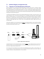
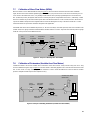
An alternative approach can be used with piston provers, as shown in Figure 6.
A cycle is initiated on the prover, which is much
slower than a Cal=Trak. The Cal=Trak is then started in a cyclical mode, averaging its flow. Before the prover ends its cycle,
the Cal=Trak is stopped and the average flow read.
The Cal=Trak can be set for sufficient cycles in its average to allow interruption by the “stop” button, or smaller averages, such
as 5 or 10 readings, can be taken during the prover cycle. It should be noted that the periodic pressure pulses might cause
oscillations in bell provers, reducing the bell prover’s accuracy somewhat.
Cal=Trak

12
Fixed
Regulator
A
djustable
Regulator
Sonic
Nozzle
OR Porous Plug
DryCal
Piston or
Bell Prover
Gas
Supply
Stable Pressure
> 200 kPa
Figure 6 Alternative Setup for Piston Provers
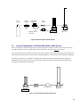
7.2 Vacuum Comparison of Cal=Trak with Piston or Bell Provers
The Cal=Trak operates similarly in both pressure and suction applications. Sometimes, however, users wish to compare the
Cal=Trak under suction (vacuum) conditions. With a piston or bell prover, the setup of Figure 7
can be used.
The restrictor should be sized to provide a drop of at least 70 kPa (21 inches or 500 mm Hg). The purpose of the restrictor is to
render the piston insertion pressure change (0.1 kPa) relatively insignificant, as in the similar pressure calibration methodology.
In volumetric, comparisons, it is important to compensate for the difference in outlet temperature from input temperature.
Although the pressure is the same on each end, the restrictor and the pump affect the outlet temperature and flow must be
normalized to the inlet (ambient) temperature.
DryCal
Vacuum Pump
Restrictor
Figure 7 Vacuum Setup for Piston or Bell Provers
Cal=Trak
Cal=Trak

13
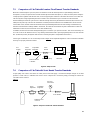
7.3 Comparison of Cal=Trak with Laminar Flow Element Transfer Standards
When the Cal=Trak begins its cycle, the piston’s acceleration causes the internal pressure to spike briefly by about 0.01
atmosphere (~1 kPa). The pressure then remains elevated by about 0.001 atmosphere (~0.1 kPa) due to the piston’s weight. If
a simple pressure regulator feeds the test chain, we are simply using the resistance of the entire flow chain to set our flow rate.
The rate may then change significantly when the Cal=Trak is in its measurement cycle. This will cause the actual flow
measured during the Cal=Trak cycles to be less than the average flow seen by the laminar flow element (LFE). Moreover, the
initial pressure pulse may cause the LFE instrument’s sensitive pressure transducers to be destabilized for several seconds.
For the latter reason, the LFE instrument should be read only immediately before the Cal=Trak reading, and afterward only
when the LFE instrument’s readings stabilize. At low flows, the Cal=Trak measurement may take sufficient time to allow LFE
stabilization. In that case, the instruments can be read simultaneously.
In addition, the flow must not be affected significantly by the Cal=Traks’s cyclic pressure increase. This can be achieved by use
of a sonic nozzle as the stable flow source, or by feeding a fixed restrictor with a precisely regulated pressure of more than 200
kPa. (At 200 kPa [30 PSI], the dynamic flow decrease caused by the piston’s weight will be about 0.05%.)
For this type of calibration, we can use the setup shown in Figure 8
. The adjustable regulator is used to set the flow rate within
the range of a properly sized flow restrictor.
Fixed
Regulator
A
djustable
Regulator
Sonic
Nozzle
OR Porous Plug
DryCal
Gas
Supply
Stable Pressure
> 200 kPa
LFE Meter
Figure 8 Setup for LFEs
7.4 Comparison of Cal=Trak with Sonic Nozzle Transfer Standards
A high quality sonic nozzle used above its critical pressure ratio will supply a constant flow despite changes in its outlet
pressure. For this reason, a calibrated sonic nozzle can be compared to a Cal=Trak by simply connecting its outlet to the
Cal=Trak’s inlet as shown in
Figure 9
.
Fixed
Regulator
A
djustable
Regulator
Sonic Nozzle
DryCal
Stable Pressure
> Critical
Pressure
Transducer
Figure 9 Setup for Sonic Nozzle Transfer Standard
Cal=Trak
Cal=Trak

14
7.5 Vacuum Comparison of Cal=Trak with Sonic Nozzle Transfer Standards
The Cal=Trak operates similarly in both pressure and suction applications. Sometimes, however, users wish to compare the
Cal=Trak under suction (vacuum) conditions. With a calibrated sonic nozzle, a simple setup such as that shown in Figure 10
can be used. There is one precaution, however. The sonic nozzle’s pressure must be measured during the Cal=Trak cycle to
obtain the actual flow that the Cal=Trak is measuring. In turn, the pressure transducer must not be upset by the Cal=Trak’s
initial pressure pulse and must have rapid response relative to the Cal=Trak cycle time. This method is therefore most suitable
for flows in the lower part of a Cal=Trak’s range. It should be noted that cycling of the Cal=Trak would cause a slight change in
the nozzle’s inlet pressure. Even though the pressure transducer is read during the Cal=Trak cycle, the nozzle may not achieve
internal thermal equilibrium during the cycle, slightly reducing accuracy.
Sonic Nozzle
DryCal
Stable Pressure
> Critical
Pressure
Transducer
Vacuum Pump
Figure 10 Vacuum Setup for Sonic Nozzle Transfer Standard
7.6 Calibration of Mass Flow Controllers (MFCs)
Modern mass flow controllers have fast response times on the order of milliseconds. They can simply be connected to an
appropriate inert gas source and their output stream applied to the Cal=Trak, as in Figure 11
. Proper calibration consists of
comparing the Cal=Trak reading to the MFCs actual indicated flow and not to its control signal. If a slow flow controller is to be
calibrated, it is best to calibrate it in its metering mode. Apply the appropriate signal to fully open the controller’s internal valve
(full scale or digital “open), and calibrate the device as shown for mass flow meters (MFMs), below.
Remember that the Cal-Trak is designed to be operated at ambient pressure. If the outlet pressure of the MFC is atmospheric,
then Figure 11 is correct. If the outlet pressure of the MFC is above ambient, insert a back-pressure regulator and a pressure
gauge between the MFC and the Cal=Trak. Adjust the back pressure regulator until the pressure gauge reads the correct
pressure for the MFC under test (usually the same pressure the device will see in its normal operation). Calibrate under the
actual operating pressures.
A
djustable
Regulator
DryCal
Gas
Supply
MFC
Figure 11 Setup for Calibrating MFCs
Cal=Trak
Cal=Trak

15
7.7 Calibration of Mass Flow Meters (MFMs)
Mass flow meters can be calibrated with the setup of Figure 12, which is similar to that shown for LFE transfer standards.
Again, the flow must not be affected significantly by the Cal=Trak’s cyclic pressure increase. This can be achieved by use of a
sonic nozzle as the stable flow source, or by feeding a fixed restrictor with a precisely regulated pressure of more than 200
kPa. (At 200 kPa [30 PSI], the dynamic flow decrease caused by the piston’s weight will be about 0.05%.) Alternately, a stable
mass flow controller may be used to maintain specific flows into the MFM under test. In this scenario, the MFC will function as
a pressure stabilizer and precision flow regulator with the Cal=Trak defining the accuracy of the device under test. Contact
Sierra Instruments for special flow controllers designed for this application.
If the MFM under test must be calibrated at pressure (i.e. because it is always used under pressure) then a fine resolution valve
(needle valve) and a gauge should be installed between the MFM and the Cal=Trak. Adjust the valve until the pressure gauge
reads the correct pressure for the MFM under test.
OR MFC
Figure 12 Setup for Calibrating Mass Flow Meters
7.8 Calibration of Rotameters (Variable Area Flow Meters)
Variable-area meters can become unstable when connected in series with a volume. Cavity resonance may even occur. They
are best calibrated using the setup of Figure 13
. The flow stream is alternately applied to the Cal=Trak and to the device under
test. A sonic nozzle or a large “swamping” pressure restriction is used to render the differences in the two devices’ insertion
pressures insignificant with respect to the required accuracy.
Figure 13 Setup for Calibrating Rotameters (Variable Area Flow Meters)
Fixed
Regulator
A
djustable
Regulator
Sonic
Nozzle
OR Porous Plug
DryCal
Gas
Supply
Stable Pressure
> 200 kPa
Flow Meter
Fixed
Regulator
Adjustable
Regulator
Sonic
Nozzle
OR Porous Plug
Stable Pressure
> 200 kPa
A
B
DryCal
Variable Area Meter
(Rotameter)
Cal=Trak
Cal=Trak

16
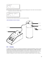
8.0 Operating Instructions
Charging the Cal=Trak Battery
The Sierra Cal=Trak is powered by an internal lead-acid battery. The battery will power the instrument for 6–8 hours of
continuous use and has a typical service life of approximately 2–4 years, depending on use. The Cal=Trak provides a
convenient 65-minute automatic shut-off to extend battery life. Use of a printer does not affect battery life.
Before using your calibrator, be sure that the battery system has been adequately charged to ensure that it will perform to its
specifications and maintain operation for the calibration period. If "B" is indicated in the upper right hand corner of the display
during operation, recharging is required.
To charge, connect the Sierra supplied charger into a standard wall outlet. Be sure to use only Sierra-approved batteries and
AC adapters/chargers for all Cal=Trak flow calibrators. Insert the Cal=Trak charger’s barrel plug end into the charging jack
located on the right side of the calibrator base. The green Charge
LED will illuminate. Full charge takes 8 –12 hours, and the
Cal=Trak can charge while being used. Upon full charge, the charger will taper to a trickle mode automatically. The unit may be
charged indefinitely without damage to the battery.
Turning the Cal=Trak On
Press On to start the Cal=Trak. An opening screen will appear indicating the instrument’s revision level followed by the “Main
Menu”.
Turning the Cal=Trak Off
The Cal=Trak has a battery saving automatic shut off system. After 65 minutes of inactivity, the Cal=Trak will shut off.
Alternatively, the unit can be shut off manually by pressing the
Reset button followed by the number 0 from the “Main Menu”.
LCD Backlight
The Cal=Trak’s LCD display includes a backlight function to illuminate the display. The default setting for the backlight is
always on. If you wish to conserve battery power you may wish to turn the backlight off or enable the backlight only when
inputting information on the keypad.
To turn the backlight off, from the “Main Menu” press the
Light button one time. To enable the backlight only when inputting
information on the keypad press the
Light button a second time. To return to the default setting of always on, press the Light
button a third time.
Low Battery Indicator
A low battery condition is indicated by a “B” appearing in the upper right hand corner of the LCD. The low battery indicator
allows the user to connect to an external power source prior to the unit powering down. Time between low battery indication
and loss of power varies depending on the current application.

17
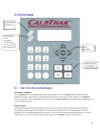
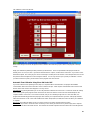
8.1 Cal=Trak Keypad
8.2 How To Use the Cal=Trak Keypad
General Menu Navigation
Use the Up/Down arrows to navigate between different lines within a menu. Use the Enter button to select a field to be
modified and to lock in any changes. Use the keypad for data entry such as entering a User ID number; use the
Up/Down
arrows to toggle fields such as temperature or pressure units. Use the
Fwd and Back keys to advance to the following menu or
return to the previous menu.
Keypad Function
The keypad is used for both numeric and alpha character entry. When pressed, each alphanumeric button will display its
corresponding number. If pressed again within two seconds the unit will display the first corresponding letter for that key.
Repeat this process for additional letters on the same key. A space may be inserted by pressing the
0 key twice. To go back,
use the back arrow. The Cal=Trak will overwrite previous entries. Use the
Enter key to lock in any selections.
Display Backlight
Control
--Default ON
--Press once OFF
--Press twice for ON
when using keys only
Press to power
Cal=Trak ON
Menu
Navigation
Primary Function
Control Buttons

18
Reset Button
Clears both the current reading and the group average and opens the valve, allowing the piston to return to its
resting state.
Stop Button
Stops current reading and opens the valve, allowing the piston to return to its resting state.
Auto Button
Initiates automatic readings (must be accessed from the “Run Menu”). If the Reading type has been set to “Cont” in “Setup
Menu – 2”, the unit will run until the preset average is reached and then start the cycle over. If the Reading type has been set to
“Burst” in “Setup Menu – 2”, the unit will run until the preset average is reached and then stop.
Read Button
Initiates a single reading (must be accessed from the “Run Menu”).
8.3 Factory Default Settings
The Sierra Cal=Trak has a number of user definable features and settings. To return to factory default settings press Reset
followed by
Save from the “Main Menu”
Parameters Factory Settings Optional Settings
No. of Readings in an Averaging Sequence 10 1–100
Atmospheric Pressure mm Hg mBar, kPa, PSI
Temperature °C °K
Standardized Temperature Setting 0 °C 0.0–50.0 °C
Date Format MM/DT/YR DT/MM/YR
Time Format AM/PM 24 Hr
8.4 Taking Readings
1 Press Enter, Read, or Auto to enter the “Run Menu”.
a. Press the
Read button to initiate a single reading.
b. Press the
Auto button to initiate multiple readings.
c. Press the
Stop button to stop current flow reading and open valve.
d. Press the
Reset button to clear the display of current data.
M
a
i
n
M
enu
Run
Setup
Leak Test

19
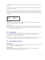
8.5 Setting User Preferences
The Sierra Cal=Trak offers enhanced electronics options that allow the user to define parameters specific to their application.
There are six Setup Menus in all. For a comprehensive flowchart of the complete menu tree, please see Appendix B.
General Menu Navigation
Use the Up/Down arrows to navigate between different lines within a menu. Use the Enter button to select a field to be
modified and to lock in any changes. Use the keypad for data entry such as # of readings in an averaging sequence; use the
Up/Down arrows to toggle fields such as temperature or pressure units. Use the Fwd and Back keys to advance to the
following menu or return to the previous menu.
Keypad Function
The keypad is used for both numeric and alpha character entry. When pressed, each alphanumeric button will display its
corresponding number. If pressed again within two seconds the unit will display the first corresponding letter for that key.
Repeat this process for additional letters on the same key. A space may be inserted by pressing the
0 key twice. To go back,
use the back arrow. The Cal=Trak will overwrite previous entries. Use the
Enter key to lock in any selections.
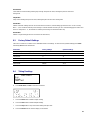
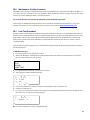
8.6 Setup Menu 1, Calibration ID #, Gas Constant, Calibration Type
To enter “Setup Menu – 1” from the “Main Menu”, select Setup and press Enter.
Option 1, “Sensor Factor”
This option changes the gas constant or K-factor for instruments that are used with any gas other than air or nitrogen, but
originally calibrated by the device manufacturer using air or nitrogen and a factor. Gas conversion factors vary by device
manufacturer. Please consult the instrument manufacturer’s gas conversion multipliers for the device under test and enter the
appropriate factor here. The input range for this option is 0.200–2.000. The default setting is for 1.000, the setting for air or
nitrogen.
Option 3, “Cal. Type”
This option changes the sample type being displayed. Toggles between “std.” (standardized or mass flow readings as used by
MFM or MFC devices) and “vol.” (volumetric readings as used on PD/rotameters)
M
a
i
n
M
enu
Run
Setup
Leak Test
Setup Menu
–
1
Sensor Factor 1.000
Cal. Type Std.

20
8.7 Setup Menu 2, Reading Type, # in Average & Minutes/Reading
Option 1, “Reading Type”
Toggles between “Cont” (continuous auto-read) and “Burst” (performs continuous auto-read, then stops after the quantity in
averaging sequence is reached [as programmed below in Setup Menu 2, Option 2, # in Average])
Option 2, “# in Average”
Changes the quantity in an averaging sequence (consecutive readings) from 1 to 100. When used in “Burst” mode, the
Cal=Trak stops after this number of readings.
Option 3, “Min./Reading”
Specifies the time interval (in minutes) between flow readings. A setting of “00” means continuous readings (no interval).
8.8 Setup Menu 3, Pressure Units, Temp. Units, and Temp. Correction Factor
Option 1, “Pres. Units”
This option allows you to toggle between pressure units of: mmHg, kPa, mBar, or PSI
Option 2, “Temp. Units”
This option allows you to set the temperature units for ° F or ° C.
Option 3, “Temp Corr”
This option is used to set the standardization (mass flow) reference temperature. Use the keypad to enter the numerical value
of the reference temperature. For mass flow units of slpm, a reference temperature of 21.1°C is commonly used. For mass
flow units of nlpm, a reference temperature of 0.0°C is common. Check the specific reference conditions for each DUT.
8.9 Setup Menu 4, Date, Time & Battery Voltage
This menu has an alternate navigation method.
Within this menu, use the
Fwd and Back arrows to change between different options and to move about within each option,
use
Up and Down arrows to alter settings. Date and time formats are specified using Setup Menu 5, Date and Time Formats.
This guide is written using the factory default settings.
Page is loading ...
Page is loading ...
Page is loading ...
Page is loading ...
Page is loading ...
Page is loading ...
Page is loading ...
Page is loading ...
Page is loading ...
Page is loading ...
Page is loading ...
Page is loading ...
Page is loading ...
Page is loading ...
Page is loading ...
Page is loading ...
Page is loading ...
-
 1
1
-
 2
2
-
 3
3
-
 4
4
-
 5
5
-
 6
6
-
 7
7
-
 8
8
-
 9
9
-
 10
10
-
 11
11
-
 12
12
-
 13
13
-
 14
14
-
 15
15
-
 16
16
-
 17
17
-
 18
18
-
 19
19
-
 20
20
-
 21
21
-
 22
22
-
 23
23
-
 24
24
-
 25
25
-
 26
26
-
 27
27
-
 28
28
-
 29
29
-
 30
30
-
 31
31
-
 32
32
-
 33
33
-
 34
34
-
 35
35
-
 36
36
-
 37
37


Sierra 500-CalTrak User manual
- Category
- Measuring, testing & control
- Type
- User manual
Ask a question and I''ll find the answer in the document
Finding information in a document is now easier with AI
Related papers
-
Sierra 800-CalTrak User manual
-
-
-
-
-
-
-
-
-
Other documents
-
 TENSITRON LX-100-1 Operating Instructions Manual
-
Atec Mesa Labs DRYCAL 1020 Gas Calibrator Rentals User manual
-
Motorola AIR-TRAK Setup Manual
-
UEi DMG150 User manual
-
MasterCool ANALOG VACUUM GAUGE Operating instructions
-
-
Meriam MFC 4102 HART Operator's Instruction Manual
-
Omega PCL4000 Owner's manual
-
Additel 949 User manual
-
DH Instruments COMPASS FOR MOLBOX User manual
