Page is loading ...

3G8080(I)/ CD8080(I)
HSPA/CDMA Controller
V1.1 Installation Manual
WARNING: This manual contains information on limitations regarding product use and function and
information on the limitations as to liability of the manufacturer. The entire manual should be carefully
read.


- 3 -
Table of Contents
Warning: Installer Please Read Carefully 5
Note to Installers 5
System Failures 5
Access by Intruders 5
Component Failure 5
Compromise of Radio Frequency (Wireless) 5
Criminal Knowledge 5
Failure of Replaceable Batteries 5
Inadequate Installation 5
Inadequate Testing 5
Insufficient Time 5
Motion Detectors 5
Power Failure 5
Security and Insurance 6
Smoke Detectors 6
Telephone Lines 6
Warning Devices 6
General 7
IMPORTANT 7
Safety Information 7
Alarm.com Introduction 7
HSPA/CDMA 3G Module - 3G8080(I)/CD8080(I) 8
Contact Information 8
Features 8
Communicator Ratings 8
Communicator Compatibility 9
Installation 10
Tools and Supplies Required 10
Enable Module 11
Connect the 3G8080(I)/CD8080(I) 11
Step 1: Connect Data Bus 11
Step 2: Connect Power 11
Step 3:Connect the PC-Link Cable 12
Step 4: Connect External Antenna (Optional) 12
Step 5: Power Up 12
HSPA/CDMA Phone Test (Module Registration) 12
Enroll Alarm.com Image Sensor 12
Panel Settings 13
Night Arming 13
Central Station and Telephone Line Settings 13
Notifications 14
Panel Settings Changed Automatically 14

Table of Contents
Clock 15
Troubleshooting 16
Module Status Information 16
Troubleshooting LEDs 16
LED Functions 17
LED Details 17
LED L1 (Red) 17
LED L2 (Yellow) 18
LED L3 (Yellow) 18
LED L4 (Green) 18
LED L5 (Yellow) 19
Various Module States (Modes) 19
Improving Wireless Signal Strength 20
Walking the Customer through New User Setup on the Web 20
Interactive Service Menu 21
Interactive Menus 21
Installer Programming 21
User Functions 22
Limited Warranty 23
International Warranty 23
Warranty Procedure 23
Conditions to Void Warranty 23
Items Not Covered by Warranty 23
Disclaimer of Warranties 23
Installer’s Lockout 23
Out of Warranty Repairs 23
End User License Agreement 24
SOFTWARE PRODUCT LICENSE 24
DESCRIPTION OF OTHER RIGHTS AND LIMITATIONS 24
LIMITED WARRANTY 25
Regulatory Information 25
FCC Statement 25
Industry Canada Statement 25
FCC/IC Label 26
- 4 -

Warning: Installer Please Read
Carefully
Note to Installers
The warnings on this page contain vital information. As the only indi-
vidual in contact with system users, it is the installer’s responsibility to
bring each item in this warning to the attention of all users of this sys-
tem.
System Failures
This system has been carefully designed to be as effective as possible.
There are circumstances, however, involving fire, burglary, or other
types of emergencies where it may not provide protection. Any alarm
system of any type may be compromised deliberately or may fail to
operate as expected for a variety of reasons. Some, but not all, of the
reasons may be:
Access by Intruders
Intruders may enter through an unprotected access point, circumvent a
sensing device, evade detection by moving through an area of insuf-
ficient coverage, disconnect a warning device, or interfere with or pre-
vent the proper operation of the system.
Component Failure
Although every effort has been made to make this system as reliable as
possible, the system may fail to function as intended due to the failure
of a component.
Compromise of Radio Frequency
(Wireless)
A device's signals may not reach the receiver under all circumstances,
which could include: metal objects placed on or near the radio path,
deliberate jamming or other inadvertent radio signal interference.
Criminal Knowledge
This system contains security features which were known to be effect-
ive at the time of manufacture. It is possible for persons with criminal
intent to develop techniques which reduce the effectiveness of these
features. It is important that your security system be reviewed peri-
odically to ensure that its features remain effective and that it is
updated or replaced if it is found that it does not provide the protection
expected.
Failure of Replaceable Batteries
This system’s wireless transmitters have been designed to provide sev-
eral years of battery life under normal conditions. The expected bat-
tery life is a function of the device environment, usage, and type.
Ambient conditions such as high humidity, high or low temperatures, or
large temperature fluctuations may reduce the expected battery life.
While each transmitting device has a low battery monitor which iden-
tifies when the batteries need to be replaced, this monitor may fail to
operate as expected. Regular testing and maintenance will keep the
system in good operating condition.
Inadequate Installation
A security system must be installed properly in order to provide
adequate protection. Every installation should be evaluated by a secur-
ity professional to ensure that all access points and areas are covered.
Locks and latches on windows and doors must be secure and operate
as intended. Windows, doors, walls, ceilings and other building mater-
ials must be of sufficient strength and construction to provide the level
of protection expected. A reevaluation must be done during and after
any construction activity. An evaluation by the fire and/or police
department is highly recommended if this service is available.
Inadequate Testing
Most problems that would prevent an alarm system from operating as
intended can be found by regular testing and maintenance. The com-
plete system should be tested weekly and immediately after a break- in,
an attempted break-in, a fire, a storm, an earthquake, an accident, or
any kind of construction activity inside or outside the premises. The test-
ing should include all sensing devices, keypads, consoles, alarm indic-
ating devices, and any other operational devices that are part of the
system.
Insufficient Time
There may be circumstances when the system will operate as intended,
yet the occupants will not be protected from an emergency due to their
inability to respond to the warnings in a timely manner. If the system is
remotely monitored, the response may not occur in time to protect the
occupants or their belongings.
Motion Detectors
Motion detectors can only detect motion within the designated areas as
shown in their respective installation instructions. They cannot dis-
criminate between intruders and intended occupants. Motion detectors
do not provide volumetric area protection. They have multiple beams
of detection and motion can only be detected in unobstructed areas
covered by these beams. They cannot detect motion which occurs
behind walls, ceilings, floors, closed doors, glass partitions, glass doors
or windows. Any type of tampering whether intentional or unin-
tentional such as masking, painting, or spraying of any material on the
lenses, mirrors, windows or any other part of the detection system will
impair its proper operation. Passive infrared motion detectors operate
by sensing changes in temperature. However their effectiveness can
be reduced when the ambient temperature rises near or above body
temperature or if there are intentional or unintentional sources of heat
in or near the detection area. Some of these heat sources could be heat-
ers, radiators, stoves, barbecues, fireplaces, sunlight, steam vents, light-
ing and so on.
Power Failure
Control units, intrusion detectors, smoke detectors and many other
security devices require an adequate power supply for proper oper-
ation. If a device operates from batteries, it is possible for the batteries
to fail. Even if the batteries have not failed, they must be charged, in
good condition and installed correctly. If a device operates only by AC
power, any interruption, however brief, will render that device inop-
erative while it does not have power. Power interruptions of any length
are often accompanied by voltage fluctuations which may damage
electronic equipment such as a security system. After a power inter-
ruption has occurred, immediately conduct a complete system test to
ensure that the system operates as intended.
- 5 -

Security and Insurance
Regardless of its capabilities, an alarm system is not a substitute for
property or life insurance. An alarm system also is not a substitute for
property owners, renters, or other occupants to act prudently to pre-
vent or minimize the harmful effects of an emergency situation.
Smoke Detectors
Smoke detectors that are a part of this system may not properly alert
occupants of a fire for a number of reasons, some of which follow.
The smoke detectors may have been improperly installed or positioned.
Smoke may not be able to reach the smoke detectors, such as when the
fire is in a chimney, walls or roofs, or on the other side of closed doors.
Smoke detectors may not detect smoke from fires on another level of
the residence or building. Every fire is different in the amount of
smoke produced and the rate of burning. Smoke detectors cannot
sense all types of fires equally well. Smoke detectors may not provide
timely warning of fires caused by carelessness or safety hazards such
as smoking in bed, violent explosions, escaping gas, improper storage
of flammable materials, overloaded electrical circuits, children playing
with matches, or arson. Even if the smoke detector operates as inten-
ded, there may be circumstances when there is insufficient warning to
allow all occupants to escape in time to avoid injury or death.
Telephone Lines
If telephone lines are used to transmit alarms, they may be out of ser-
vice or busy for certain periods of time. Also an intruder may cut the
telephone line or defeat its operation by more sophisticated means
which may be difficult to detect.
Warning Devices
Warning devices such as sirens, bells, horns, or strobes may not warn
people or waken someone sleeping if there is an intervening wall or
door. If warning devices are located on a different level of the res-
idence or premise, then it is less likely that the occupants will be aler-
ted or awakened. Audible warning devices may be interfered with by
other noise sources such as stereos, radios, televisions, air conditioners,
other appliances, or passing traffic. Audible warning devices, however
loud, may not be heard by a hearing-impaired person.
- 6 -

General
IMPORTANT
This installation manual shall be used in conjunction with the control panel. All the safety instructions specified
within that manual shall be observed. The control panel is referenced as the “panel” throughout this document.
This installation guide provides the basic wiring, programming and troubleshooting information. Use this guide
in conjunction with the installation manual available online from the DSC website at www.dsc.com.
The HSPA/CDMA alarm communicator is a fixed, wall-mounted unit, and shall be installed in the location spe-
cified in these instructions. The HSPA/CDMA alarm communicator module should NOT be installed inside of
the metal alarm panel casing; doing so will significantly impair cellular and RF (Z-Wave, Image Sensor) trans-
missions.The equipment enclosure must be fully assembled and closed, with all the necessary screws/tabs, and
secured to a wall before operation. Internal wiring must be routed in a manner that prevents:
l Excessive strain on wire and on terminal connections,
l Interference between power limited and non power limited wiring,
l Loosening of terminal connections, or
l Damage of conductor insulation.
WARNING: Never install this equipment during a lightning storm.
Safety Information
The installer must instruct the system user on each of the following:
l Do not attempt to service this product. Opening or removing covers may expose the user to dangerous
voltages or other risks.
l Any servicing shall be referred to service persons only.
l Use authorized accessories only with this equipment.
l Do not stay close to the equipment during device operation.
l Do not touch the external antenna.
Alarm.com Introduction
The purpose of this guide is to introduce you to the Alarm.com communicator modules. The following sections
identify these modules and offer you a brief overview of their capabilities. Some capabilities and features vary
based on the Alarm.com service plan selected. Visit www.alarm.com/Dealer or contact Alarm.com for more
information.
Note: Both the HSPA3G module and the CDMA module are available in the following models:
Module Model
HSPA3G 3G8080
3G8080(I)*
CDMA CD8080
CD8080(I)*
* Image Sensor Compatible
The module 3G8080(I) contains the subassembly 3G8055(I) NEO and the PC-Link to the RS422 conversion
interface. The module is compatible only with NEO Alarm Control Unit models HS2128, HS2064, HS2032
and HS2016 software versions 1.1 and above.
- 7 -

- 8 -
The module CD8080(I) contains the subassembly CD8055(I) NEO and the PC-Link to RS422 conversion inter-
face. The module is compatible only with NEO Alarm Control Unit models HS2128, HS2064, HS2032 and
HS2016 software versions 1.1 and above.
HSPA/CDMA 3G Module - 3G8080(I)/CD8080(I)
The HSPA/CDMA module enables wireless reporting of all alarms and other system events from the DSC
Neo control panel using an all-digital, HSPA/CDMA wireless (cellular) network. The module can be used as
the primary communication path for all alarm signaling, or as a backup to a telephone connection to the central
monitoring station. The wireless alarm signaling and routing service is operated by Alarm.com. The
HSPA/CDMA module also features integrated support for Alarm.com’s home automation solution with built- in
Z-Wave capabilities. A 3G8080(I) or CD8080(I) is required to support the Alarm.com Image Sensor.
Note: Alarm.com’s home automation solution with built-in Z-Wave capabilities is not UL/ULC evaluated.
Contact Information
For additional information and support on Alarm.com modules, initial account setup, home automation, and all
other Alarm.com products and services, please visit: www.Alarm.com/dealer or contact Alarm.com technical
support at: 1-866-834-0470.
Features
l 128-bit AES encryption via cellular and Internet (NIST validation certificate number: 3162).
l Back up or primary cellular alarm communication.
l Automatically switches to 2G (EDGE/GPRS) if HSPA(3G) service is not available.
l Full event reporting to central station (UL/ULC listed).
l Cellular periodic test transmission.
l Integrated call routing.
l Remote firmware upgrade capability of the communicator and panel firmware via cellular.
l Panel remote uploading/downloading support via cellular.
l PC-LINK connection.
l Programmable labels.
l SIA and Contact ID (CID) formats supported.
l Signal strength and trouble display LEDs.
l Subscriber Identity Module (SIM) card included with communicator.
l Supervision heartbeats sent via cellular.
l 2-way audio capable when used with audio module HSM2955(R) - Refer to HSM2955(R) manual
Communicator Ratings
Model 3G8080(I) CD8080(I)
Power Supply Ratings
Input Voltage 11.3V - 12.5V DC
Current Consumption
Standby Current 100mA@12V (I) 100mA@12V (I)
Alarm (Transmitting) Current 200mA@12V (I) 200mA@12V (I)
Cellular Network HSPA 3G CDMA
Operating Frequency 850, 1900, 2100MHz 850, 1900, 2100MHz
Environmental Specifications
Operating Temperature
14°F to 131°F (-10°C to 55°C)
UL/ULC verified operation for 32°F-120°F (0°C-49°C) only
Storage Temperature -30°F to 140°F (-34°C to 60°C)

Model 3G8080(I) CD8080(I)
Humidity 90%non-condensing
Mechanical Spec7ifications
Dimensions 6" x 8.9" x 1.3"
Weight (grams) 365g (I) 360g (I)
Communicator Compatibility
Communicator
Receiver/
Panel
Description
3G8080(I)
CD8080(I)
Receiver
l Sur-Gard System I-IP Receiver, version 1.13+
l Sur-Gard System II Receiver, version 2.10+
l Sur-Gard SG-DRL3-IP, version 2.30+ (for Sur-Gard System III
Receiver)
l Sur-Gard SG-DRL4-IP version 1.20+ (for Sur-Gard System IV
Receiver)
l Sur-Gard SG-DRL5-IP version 1.00+ (for Sur-Gard System 5
Receiver)
Panel
l HS2016, version 1.1+
l HS2032, version 1.1+
l HS2064, version 1.1+
l HS2128, version 1.1+
Note: Enter [*][8][Installer Code][900][000] at keypad to view the panel version number.
Products or components of products, which perform communications functions only shall comply with the
requirements applicable to communications equipment as specified in UL60950 or CAN CSA C22.2. No.
60950-1, Information Technology Equipment - Safety - Part 1: General Requirements. Where network inter-
faces are external to the control unit or receiver, compliance to CAN CSA C22.2. No. 60950-1 is adequate.
Such components include, but are not limited to: hubs; routers; NIDs; third-party communications service pro-
viders; DSL modems; and cable modems.
- 9 -

- 10 -
Installation
INSTALLATION
Follow these guidelines during installation.
l Before affixing the communicator to a wall, verify the HSPA/CDMA signal level at the installation loc-
ation. On a keypad, press and hold the 5 key for 2 seconds to view the HSPA/CDMA signal level. An
installation location with a sustained signal level of two or more bars is recommended.
l Do not exceed the panel total output power when using panel power for the 3G8080/CD8080 module, hard-
wired sensors, and /or sirens. Refer to the specific panel installation instructions for details. Only one
3G8080/CD8080 module can be used per panel.
l To minimize potential interference with cellular signaling, avoid mounting the communicator in areas with
excessive metal or electrical wiring, such as furnaces or utility rooms.
Do not mount the 3G8080(I)/CD8080(I) communicator inside of the metal alarm panel enclosure.
Tools and Supplies Required
You will need the following tools and supplies:
l Small flat-head and Phillips screwdrivers
l Screws (included)
l Antenna (included)
l 16 pin ribbon cable (included)
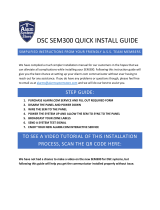
HS2016/2032/2064/2128
PCLINK_2
A
Alarm Controller Cabinet
HSPA/CDMA Controller
C
B

D
PCL-422
Mounted in Alarm Controller Cabinet
HSPA/CDMA Controller Board
RX-
RX+
TX+
TX-
+12V
GND
E
+12V
GND
A Red wire on alarm controller PCLink_2 Header
B Antenna access ports
C Quad cables (100' / 30m maximum)
D Red wire on PCL-422 PCLink Header
E HSPA/CDMA Controller Board power terminals. Can be connected to power supply module (HSM2204/2300).
Enable Module
For the Alarm.com module to communicate with the panel, section [382] option 5 at the panel must be set to
ON. This section is OFF by default and must be enabled for the system to function properly. This should be
done before connecting the PC Link cable to power up the module to ensure all initialization commands are pro-
cessed properly.
Connect the 3G8080(I)/CD8080(I)
Caution: Ensure that the alarm panel is fully powered down (i.e., AC and battery disconnected) prior to con-
necting the 3G8080(I)/CD8080(I).
Step 1: Connect Data Bus
The maximum cable length permitted for the data bus is 100ft/30m.
l Connect the RX+ terminal on the 3G8080(I)/CD8080(I) to the TX+ terminal on the PCL-422
l Connect the RX- terminal on the 3G8080(I)/CD8080(I) to the TX- terminal on the PCL-422
l Connect the TX- terminal on the 3G8080(I)/CD8080(I) to the RX- terminal on the PCL-422
l Connect the TX+ terminal on the 3G8080(I)/CD8080(I) to the RX+ terminal on the PCL-422
Step 2: Connect Power
The maximum cable length permitted for the power connection is 100ft/30m.
l Connect the GND terminal on the 3G8080(I)/CD8080(I) to the GND terminal on the PCL-422
l Connect the +12V terminal on the 3G8080(I)/CD8080(I) to the +12V terminal on the PCL-422
- 11 -
Installation

- 12 -
Installation
Step 3:Connect the PC-Link Cable
Note: To ensure correct orientation, refer to items A and C in the wiring diagrams for the proper position of
the red wire on the PC-link cable.
l Connect one end of the supplied PC-Link cable to the PC-Link header on the PCL-422
l Connect the other end of the PC-Link cable to the PC-LINK_2 header on the alarm panel
Step 4: Connect External Antenna (Optional)
Upgraded antennas are available for the 3G8080(I) /CD8080(I) if there is inadequate cellular reception at the
preferred mounting location. Contact DSC technical support for antenna options.
The 3G8080(I)/CD8080(I) has two covered access ports on the top of the enclosure. Remove the plastic tab
covering the desired port and either mount the antenna on the enclosure or use the opening to pass through the
antenna cable.
Note: Due to the curvature of the enclosure, the plastic port covers are NOT interchangeable. Ensure that any
unused ports are covered with their original plastic tab.
Warning: The external antenna must be installed in a manner to prevent end users from accessing any con-
ductive part of the anntena or antenna cable (i.e., recessed mounting or equivalent).
Step 5: Power Up
Connect panel battery and AC power. Once an HSPA/CDMA module is connected to a powered control panel,
view key items on the LCD. Ensure that the module has been fully connected to the alarm panel via quad cable
as shown in wiring diagram.
HSPA/CDMA Phone Test (Module Registration)
To initiate module communication with Alarm.com and the HSPA/CDMA network for the first time, perform
an “HSPA/CDMA phone test”. Note that the phone test can also be used at any time by the installer to force
communication with Alarm.com. Perform a phone test by pressing and holding [3] for two seconds. A phone
test can also be completed through the Interactive Services menu. To perform the phone test, press [*][6] fol-
lowed by the master code and [04].
The panel indicates when the HSPA/CDMA phone test has completed by activating the siren output on medium
volume for 2 seconds followed by full volume for 2 seconds. However, if the phone test was initiated via the
[3] key, or through the Interactive Services menu, the siren will not sound. All display lights and LCD pixels
turn on. This indicates that Alarm.com has received and acknowledged the signal. This does not guarantee that
the signal went through to a central station; it confirms that Alarm.com’s Network Operations Center received
the signal. The central station should be contacted directly to verify that the signal was received on the correct
account and that the central station routing settings have been set up correctly. If the signal does not go through
to the Central Station, the panel will display a “Failure to Communicate” message. Double check the account’s
Central Station Forwarding Settings on Alarm.com and contact technical support if the trouble persists.
Enroll Alarm.com Image Sensor
Note: The Alarm.com Image Sensor is compatible with models ending with "I" (i.e., 3G8080I and CD8080I).
1. Ensure batteries are removed from the sensor.
2. On the panel, enter the Interactive Services menu. Interactive Services can be accessed, via section [851]
of Installer Programming.
3. Press [*][8] [Installer Code] [851].
4. Scroll to Image Sensor Setup and press [*].
5. Scroll to Learn Image Sensor and press [*]. The keypad will display “Power up or reset I.S. now.”

6. Insert the batteries into the sensor. Wait approximately 20 seconds for the control panel screen to display:
“I.S. [x] Added as Sensor [y].” The LED on the sensor will turn solid for 5 seconds once the sensor has
enrolled.
7. Perform another panel comm-test to ensure that Alarm.com receives the updated device equipment list.
This will speed up the sensor initialization process.
l The zone will be configured as a virtual zone and programmed automatically into the next available slot in
section [560][001]-[032] starting at zone 126 and counting down for each additional Image Sensor added.
l Once enrolled, the Image Sensor will appear as a normal zone.
l By default, the Image Sensor is enrolled as an Interior Stay/Away zone in zone type 005. Zone type and
attributes can be assigned in the installer menu, in a similar way as regular zones. For more information,
refer to the "Zone Setup" section of the PowerSeries Neo Alarm Controller Reference Manual.
Panel Settings
Night Arming
The panel has the ability to night arm, which arms the perimeter and restricts movement to designated interior
areas. Night arming via the panel should be restricted to one of the five function keys. For more information on
Night Arming and how to program the function keys, see the installation guide provided with the panel.
Central Station and Telephone Line Settings
Central Station and telephone line settings will be automatically configured through the CS Forwarding Set-
tings page of the Alarm.com Dealer Site. The following are the panel settings that will be configured via the
Dealer Site page (when required) and should not be configured in the panel:
Section Option Description
015 7 Telephone line monitoring
300 [001] -- Panel Communication Path - Receiver 1
300 [002] -- Panel Communication Path - Receiver 2
300 [003] -- Panel Communication Path - Receiver 3
300 [004] -- Panel Communication Path - Receiver 4
301 [001] -- Communication telephone number 1
301 [002] -- Communication telephone number 2
301 [003] -- Communication telephone number 3
301 [004] -- Communication telephone number 4
309 [001] -- System Call Direction - Maintenance
309 [002] -- System Call Direction - Test Transmission
310 [000] -- System account number
310 [001] -- Partition 1 account number
310 [002] -- Partition 2 account number
310 [003] -- Partition 3 account number
310 [004] -- Partition 4 account number
310 [005] -- Partition 5 account number
310 [006] -- Partition 6 account number
310 [007] -- Partition 7 account number
310 [008] -- Partition 8 account number
311 [001] -- Partition 1 Call Direction - Alarm/Restore
- 13 -
Installation

- 14 -
Installation
Section Option Description
311 [002] -- Partition 1 Call Direction - Tamper/Restore
311 [003] -- Partition 1 Call Direction - Opening/Closing
312 [001] -- Partition 2 Call Direction - Alarm/Restore
312 [002] -- Partition 2 Call Direction - Tamper/Restore
312 [003] -- Partition 2 Call Direction - Opening/Closing
313 [001] -- Partition 3 Call Direction - Alarm/Restore
313 [002] -- Partition 3 Call Direction - Tamper/Restore
313 [003] -- Partition 3 Call Direction - Opening/Closing
314 [001] -- Partition 4 Call Direction - Alarm/Restore
314 [002] -- Partition 4 Call Direction - Tamper/Restore
314 [003] -- Partition 4 Call Direction - Opening/Closing
315 [001] -- Partition 5 Call Direction - Alarm/Restore
315 [002] -- Partition 5 Call Direction - Tamper/Restore
315 [003] -- Partition 5 Call Direction - Opening/Closing
316 [001] -- Partition 6 Call Direction - Alarm/Restore
316 [002] -- Partition 6 Call Direction - Tamper/Restore
316 [003] -- Partition 6 Call Direction - Opening/Closing
317 [001] -- Partition 7 Call Direction - Alarm/Restore
317 [002] -- Partition 7 Call Direction - Tamper/Restore
317 [003] -- Partition 7 Call Direction - Opening/Closing
318 [001] -- Partition 8 Call Direction - Alarm/Restore
318 [002] -- Partition 8 Call Direction - Tamper/Restore
318 [003] -- Partition 8 Call Direction - Opening/Closing
350 [001] -- Receiver 1 communicator format
350 [002] -- Receiver 2 communicator format
384 2 Communicator backup options
Notifications
The following panel settings may alter the behavior of customer notifications:
Section Option Description
015 4
If this option is ON, keyfob arming notifications will not be associated with a specific
user
Panel Settings Changed Automatically
Some panel settings are changed automatically when the HSPA/CDMA module is connected to the control
panel. These settings should not be altered. They are:
Section Option Value Description
015 6 OFF
Master code is not changeable and must be
OFF to ensure the module communicates the
correct master code

Section Option Value Description
017 6 OFF
Daylights saving time must be disabled to
ensure panel time is accurate
019 6
Set according to
dealer's Alarm.com
setting
Enables Duress Code changes from
Alarm.com
024 5 OFF
Realtime clock must be disabled to ensure
panel time is accurate
041 - 00 User Access Codes must be 4-digits
377
Swinger Shutdown
(Maintenance)
014
Swinger Shutdown for maintenance signals
must be set to 014 to ensure trouble
notifications can be sent.
377
AC Failure
Communication Delay
Random value between
001 and 030
AC Failure Communication Delay should be
set between 001 and 030 to ensure
notifications for power failures are received
377
Wireless Device Low
Battery Transmission
Delay
001
Wireless Device Low Battery Transmission
Delay should be set to 001 to ensure
notifications for low batteries are received
380 1 ON
Communications must be enabled for the
module to communicate with the panel
380 2 OFF
System should transmit alarm restores
immediately when the zone is restored
380 5 OFF
The redundant communications method must
be set as backup.
382 6 OFF
AC Failure Transmission Delay should be in
minutes
804 [sensor #] 003 Five minute delay [07]
High Traffic Shutdown should be set to five
minutes for devices being used with
Alarm.com's Activity Monitoring.
Note: This feature may reduce the battery
life of wireless PIR sensors. In order to
avoid this, hardwired PIR sensors may be
used instead.
Clock
The HSPA/CDMA module sets the panel clock when it connects to Alarm.com and then updates it every 18
hours. It is important to select the correct panel time zone on the Alarm.com website, or the panel time will
not be accurate. If a system is powered up before the customer account has been created, the time zone will
default to Eastern Standard Time.
- 15 -
Installation

- 16 -
Troubleshooting
TROUBLESHOOTING
Module Status Information
Module status information for verifying and troubleshooting the module connection status or errors can be
found through the Interactive Services menus. To access these, press [*][8][Installer Code][851]. See the fol-
lowing table for potential module states.
Status Description
Idle Most common state. Module is not actively sending data and no errors are present.
Roaming Roaming on partner network.
SIM Missing The SIM card is missing. Not applicable to CDMA.
PowerSave
Mode
AC power is down.
Registering... The module is trying to register on the HSPA/CDMA network.
Connection
Error
The module is registered on the HSPA/CDMA network but cannot connect with Alarm.com. Contact
Alarm.com technical support for more information.
Radio Error
Radio portion of the module is not operating correctly. Power cycle the panel and call Alarm.com
technical support if the trouble persists.
Server Error Identifies a server error. If it persists, the account may have been set up incorrectly.
Connected Currently connected and transmitting information to the Alarm.com servers.
Connecting... In the process of connecting to Alarm.com.
Updating... Updating signal level.
In addition, some of the information can be retrieved via long key presses from the keypad. Press and hold the
following panel keys for 2 seconds to display the given information on the panel display. Most messages are dis-
played for less than 30 seconds but can be cut short by pressing the 0 Key for 2 seconds.
Status
Keys
Description
1 key
10-digit module serial number needed to create the Alarm.com customer account.
2 key Module firmware version (e.g., 181a).
3 key
Initiate communication test.
Important: This test is required to correctly complete the installation.
4 key
Use only when instructed by Alarm.com Technical Support.
5 key
Wireless signal strength level and module status or error, if any. The panel will display the signal level in
bars (0 to 5) and as a numerical value (0 to 31) followed by the connection mode (HSPA/CDMA).
6 key
Battery voltage as read by the module, to two decimal places, and the AC power status. (e.g., Battery:
6.79v, AC Power OK).
7 key
Use only when instructed by Alarm.com Technical Support.
8 key
HSPA/CDMA frequency used by the module: "High" = 1900MHz, 2100MHz; "Low" = 850 MHz. The panel
will specify either “3G” or “2G” depending on your coverage, but will always attempt to go to 3G coverage.
Troubleshooting LEDs
Status LEDs indicate network and module status. The following figure shows the location of the status LEDs
on the HSPA/CDMA module.

Status LEDs
L1 L2 L3 L4 L5
LED Functions
LED Function
L1
Error LED. Flashes 1 to 8 times in an 8-second interval to indicate specific error. See section "LED L1 (red)" for
errors and common fixes.
L2
Panel Communication and Z-Wave status messages. Flashes every time the module communicates with the
panel and flashes in patterns to indicate Z-Wave status.
L3
HSPA /CDMA Communication. Flashes every time the HSPA/CDMA signal level is checked and when
packets are exchanged with Alarm.com.
L4
HSPA/CDMA Signal Level. Flashes 0 to 5 times to indicate signal strength, or toggles on/off slowly when
communicating with Alarm.com servers.
L5 Z-Wave Error LED. See section "LEDL5 (yellow)" for error descriptions.
LED Details
LED L1 (Red)
L1 flashes when there is an error. The number of flashes indicates the error number. If there are two or more
errors at the same time, the errors will flash one after the other. The LED will stay off for at least four
seconds between errors.
Number
of
Flashes
Error and Solution
1
Module cannot communicate with the panel. Ensure section [382] option [5] is ON. Verify panel
software is version 1.1 or higher. Check the connectors (between the panel and communicator) and
powercycle the panel. If the error persists, there may be an issue with the module or panel.
- 17 -
Troubleshooting

- 18 -
Troubleshooting
Number
of
Flashes
Error and Solution
2
The SIM card is missing. The SIM card holder can be found on the module. Verify that the SIM card holder
is closed securely and that there is a SIM card in the holder.
3
The module is trying to register on the HSPA/CDMA network. If it persists for more than a few minutes,
the module is having problems registering with the HSPA/CDMA network. Check L4 for signal level. If
signal level is lower than 2 “bars”, change the panel’s location or use a remote antenna option. If the signal
is good, the module may be roaming on a HSPA/CDMA network that does not partner with our
HSPA/CDMA providers, or the SIM card was not activated yet because the Alarm.com account was not
created correctly.
4
The module is registered on the HSPA/CDMA network but cannot connect with Alarm.com. Power down
the module, wait one minute, restore power and perform a communications test. Verify signal strength
and try a different location for the module/antenna. If the problem persists, contact Alarm.com Technical
Support.
5
Radio portion of the module is not working correctly. If this persists for more than a few minutes the
module may need to be replaced. This error is extremely rare so verify that the module is flashing 5 times.
6
This is an error only if it persists for more than a minute. Otherwise, it is just an indication that the module
is fixing an unusual condition regarding communication with the HSPA/CDMA network.
7 The module is not compatible with this panel type. Please insert a compatible module.
8
If it persists, the account may have been set up incorrectly. Contact Alarm.com Technical Support. You
will be asked to check the serial number of the module.
LED L2 (Yellow)
L2 flashes with every communication between the module and the panel. Normal pattern calls for a series of
quick flashes every two seconds in Idle mode or four seconds in PowerSave mode. It also occasionally flashes
in patterns to indicate Z-Wave status. Refer to the following table for a description of the various possibilities.
LED 2 Device Status or Error Description
4-blinks
Add Mode (lasts 120 seconds or
until a device is added)
In this mode you can add a device to the local Z-Wave network.
Devices cannot be added to a network if they are already a part
of a network.
2-blinks
Delete Mode (lasts 120 seconds or
until a device is deleted)
In this mode you can delete a device from a Z-Wave network. A
device can only be in one network at a time, and must receive a
“delete” command before it can be learned into a new network.
Solid
Successful add node/remove
node/replication (lasts 60 seconds)
After receiving this signal, leave all devices by the
HSPA/CDMA module for 1 minute. Locks must be left next to
the module for 4 minutes.
Solid with
one blink
Add node attempt failed because
node already in network (lasts 60
seconds)
Device you attempted to add to a network is already in a
network, and must be “deleted” before it can join a new
network.
LED L3 (Yellow)
L3 flashes with every communication between the module and its radio unit in Idle mode, and with every com-
munication with Alarm.com in Connected mode. In PowerSave mode, this LED flashes in unison with LED 2.
LED L4 (Green)
L4 indicates the HSPA/CDMA signal level as a number of flashes (0 to 5 bars). The number of bars may not
correspond to the bars shown on your cell phone. A level of 5 bars is obtained only in the strongest signal con-
ditions.

Signal level is updated every ten seconds if it fluctuates, or every 30 seconds if it is fairly stable. If L4 is not
flashing it indicates one of the following states:
l The module is in PowerSave mode
l The module just powered up
l There is no HSPA/CDMA coverage in the area. Alarm.com recommends a steady signal level of 2 or
higher for proper operation of the module
Note: In Connected Mode, the LED toggles on and off.
LED L5 (Yellow)
L5 indicates Z-Wave errors. See the table below for more information.
LED 5 Device Status or Error Description
2-blinks
No other nodes are in the network
(lasts until a device is added to the
network)
No devices have been added that can be controlled by the
HSPA/CDMA module yet. See above for instructions on how to
add devices.
5-blinks
Learn mode error (lasts 60
seconds)
Learn mode error (lasts 60 seconds).
6-blinks
No Home ID present (lasts until the
module connects to Alarm.com
and is configured)
When the HSPA/CDMA module first connects to Alarm.com it
is configured with a necessary unique network ID.
Various Module States (Modes)
There are four module states, or modes, as described in the following:
Mode Description
Idle AC power is okay and the module is not currently talking to Alarm.com
L1 - Flashes error, if any
L2 - Communication with panel
L3 - Communication with radio unit
L4 - Signal level (0 to 5 bars)
L5 - Flashes errors, if any
PowerSave
The module just powered up, AC power is down, or AC power was recently restored and the battery is
recharging. The module is fully functional and will go into Connected mode as soon as a signal needs to
be sent. Press and hold the 5 Key for 2 seconds to switch the module into Idle mode and update the
signal level reading. The system will go into Idle mode every 2 hours to check for any incoming
messages
L1 - Inactive
L2 - Communication with panel
L3 - Same flashing pattern as L2
L4 - Inactive
L5 - Inactive
Connected
The module is currently talking to Alarm.com. The module stays in Connected mode for at least four
minutes after reporting an event to Alarm.com, unless the 5 Key is pressed and held for 10 seconds,
which will cause the module to go back to Idle mode
L1 - Flashes errors, if any
L2 - Communication with panel
L3 - Communication with Alarm.com
L4 - Alternates two seconds on, then two seconds off
L5 - Inactive
Sleep
The panel is not connected to AC power, or there is an AC power failure, and the battery level is low. The
module will connect to Alarm.com to send a signal, but will otherwise draw almost no power.
- 19 -
Troubleshooting

- 20 -
Troubleshooting
Note: If the HSPA/CDMA module is powered down for a short period of time, buffered messages from
Alarm.com may be received when module power is restored.
Improving Wireless Signal Strength
As you make changes to the module location to improve signal strength, request updated signal readings to
verify changes. To request an updated reading, press and hold the “5” key for 2 seconds. In the image below,
the radio has 3 out of 5 bars or 13/31 and is connected to the network.
Radio: 123__ 13
Connected
Guidelines for optimal wireless signal strength:
l Install the module above ground level, as high up as possible within the structure.
l Install the module near or adjacent to an exterior-facing wall of the structure.
l Do not install the module inside a metal structure or close to large metal objects or ducts.
l Upgrade the antenna. Contact DSC technical support for antenna options.
Walking the Customer through New User Setup on the Web
This section describes how to help your customer set up their website account, and only applies to customers on
an interactive service plan with an online account. (Skip this step for customers using the module for wireless
signaling only).
Before the customer can configure their website account, the Alarm.com account for that customer must be
created on the Dealer Site, and the HSPA/CDMA module associated with the account must be installed suc-
cessfully.
To log in and access their account, the customer can go to www.alarm.com (or custom dealer website address)
to complete the new subscriber setup procedure.
The customer will need the following:
l The web site login and temporary password included on the Alarm.com Welcome Letter, which is gen-
erated when the account was created by the dealer
l A list of their system sensors with corresponding zone IDs
l At least one phone number and e-mail address where notifications can be sent
Note: At least one sensor must be learned into the panel to complete the new subscriber setup. If not all
sensors and touch screens were learned in before powering up the module, an updated sensor list must be
requested by performing a HSPA/CDMA phone test or requesting an updated equipment list from the Dealer
Site.
/