Page is loading ...

NOTE: This manual contains information regarding product use and function, in addition to manufacturer
liability and restrictions pertaining to it. The entire manual should be read carefully
.
version 2.0
SG-System III
Operating Manual

WARNING Please Read Carefully
Note to Installers
This warning contains vital information. As the only individual in contact with system users, it is your
responsibility to bring each item in this warning to the attention of the users of this system.
System Failures
This system has been carefully designed to be as effective as possible. There are circumstances, however,
involving fire, burglary, or other types of emergencies where it may not provide protection. Any alarm
system of any type may be compromised deliberately or may fail to operate as expected for a variety of
reasons. Some but not all of these reasons may be:
• Inadequate Installation
A security system must be installed properly in order to provide adequate protection. Every installation
should be evaluated by a security professional to ensure that all access points and areas are covered.
Locks and latches on windows and doors must be secure and operate as intended. Windows, doors, walls,
ceilings and other building materials must be of sufficient strength and construction to provide the level of
protection expected. A reevaluation must be done during and after any construction activity. An evalua-
tion by the fire and/or police department is highly recommended if this service is available.
• Criminal Knowledge
This system contains security features which were known to be effective at the time of manufacture. It is
possible for persons with criminal intent to develop techniques which reduce the effectiveness of these
features. It is important that a security system be reviewed periodically to ensure that its features remain
effective and that it be updated or replaced if it is found that it does not provide the protection expected.
• Access by Intruders
Intruders may enter through an unprotected access point, circumvent a sensing device, evade detection by
moving through an area of insufficient coverage, disconnect a warning device, or interfere with or prevent
the proper operation of the system.
• Power Failure
Control units, intrusion detectors, smoke detectors and many other security devices require an adequate
power supply for proper operation. If a device operates from batteries, it is possible for the batteries to
fail. Even if the batteries have not failed, they must be charged, in good condition and installed correctly.
If a device operates only by AC power, any interruption, however brief, will render that device inopera-
tive while it does not have power. Power interruptions of any length are often accompanied by voltage
fluctuations which may damage electronic equipment such as a security system. After a power interrup-
tion has occurred, immediately conduct a complete system test to ensure that the system operates as
intended.
• Failure of Replaceable Batteries
This system’s wireless transmitters have been designed to provide several years of battery life under nor-
mal conditions. The expected battery life is a function of the device environment, usage and type. Ambi-
ent conditions such as high humidity, high or low temperatures, or large temperature fluctuations may
reduce the expected battery life. While each transmitting device has a low battery monitor which identi-
fies when the batteries need to be replaced, this monitor may fail to operate as expected. Regular testing
and maintenance will keep the system in good operating condition.
• Compromise of Radio Frequency (Wireless) Devices
Signals may not reach the receiver under all circumstances which could include metal objects placed on
or near the radio path or deliberate jamming or other inadvertent radio signal interference.
• System Users
A user may not be able to operate a panic or emergency switch possibly due to permanent or temporary
physical disability, inability to reach the device in time, or unfamiliarity with the correct operation. It is
important that all system users be trained in the correct operation of the alarm system and that they know
how to respond when the system indicates an alarm.
• Smoke Detectors
Smoke detectors that are a part of this system may not properly alert occupants of a fire for a number of
reasons, some of which follow. The smoke detectors may have been improperly installed or positioned.
Smoke may not be able to reach the smoke detectors, such as when the fire is in a chimney, walls or roofs,
or on the other side of closed doors. Smoke detectors may not detect smoke from fires on another level of
the residence or building.
Every fire is different in the amount of smoke produced and the rate of burning. Smoke detectors cannot
sense all types of fires equally well. Smoke detectors may not provide timely warning of fires caused by
carelessness or safety hazards such as smoking in bed, violent explosions, escaping gas, improper storage
of flammable materials, overloaded electrical circuits, children playing with matches or arson.
Even if the smoke detector operates as intended, there may be circumstances when there is insufficient
warning to allow all occupants to escape in time to avoid injury or death.
• Motion Detectors
Motion detectors can only detect motion within the designated areas as shown in their respective installa-
tion instructions. They cannot discriminate between intruders and intended occupants. Motion detectors
do not provide volumetric area protection. They have multiple beams of detection and motion can only be
detected in unobstructed areas covered by these beams. They cannot detect motion which occurs behind
walls, ceilings, floor, closed doors, glass partitions, glass doors or windows. Any type of tampering
whether intentional or unintentional such as masking, painting, or spraying of any material on the lenses,
mirrors, windows or any other part of the detection system will impair its proper operation.
Passive infrared motion detectors operate by sensing changes in temperature. However their effectiveness
can be reduced when the ambient temperature rises near or above body temperature or if there are inten-
tional or unintentional sources of heat in or near the detection area. Some of these heat sources could be
heaters, radiators, stoves, barbeques, fireplaces, sunlight, steam vents, lighting and so on.
• Warning Devices
Warning devices such as sirens, bells, horns, or strobes may not warn people or waken someone sleeping
if there is an intervening wall or door. If warning devices are located on a different level of the residence
or premise, then it is less likely that the occupants will be alerted or awakened. Audible warning devices
may be interfered with by other noise sources such as stereos, radios, televisions, air conditioners or other
appliances, or passing traffic. Audible warning devices, however loud, may not be heard by a hearing-
impaired person.
• Telephone Lines
If telephone lines are used to transmit alarms, they may be out of service or busy for certain periods of
time. Also an intruder may cut the telephone line or defeat its operation by more sophisticated means
which may be difficult to detect.
• Insufficient Time
There may be circumstances when the system will operate as intended, yet the occupants will not be pro-
tected from the emergency due to their inability to respond to the warnings in a timely manner. If the sys-
tem is monitored, the response may not occur in time to protect the occupants or their belongings.
• Component Failure
Although every effort has been made to make this system as reliable as possible, the system may fail to
function as intended due to the failure of a component.
• Inadequate Testing
Most problems that would prevent an alarm system from operating as intended can be found by regular
testing and maintenance. The complete system should be tested weekly and immediately after a break-in,
an attempted break-in, a fire, a storm, an earthquake, an accident, or any kind of construction activity
inside or outside the premises. The testing should include all sensing devices, keypads, consoles, alarm
indicating devices and any other operational devices that are part of the system.
• Security and Insurance
Regardless of its capabilities, an alarm system is not a substitute for property or life insurance. An alarm
system also is not a substitute for property owners, renters, or other occupants to act prudently to prevent
or minimize the harmful effects of an emergency situation.
Limited Warranty
Digital Security Controls warrants the original purchaser that for a period of twelve months from the date
of purchase, the product shall be free of defects in materials and workmanship under normal use. During
the warranty period, Digital Security Controls shall, at its option, repair or replace any defective product
upon return of the product to its factory, at no charge for labour and materials. Any replacement and/or
repaired parts are warranted for the remainder of the original warranty or ninety (90) days, whichever is
longer. The original purchaser must promptly notify Digital Security Controls in writing that there is
defect in material or workmanship, such written notice to be received in all events prior to expiration of
the warranty period. There is absolutely no warranty on software and all software products are sold as a
user license under the terms of the software license agreement included with the product. The Customer
assumes all responsibility for the proper selection, installation, operation and maintenance of any prod-
ucts purchased from DSC. Custom products are only warranted to the extent that they do not function
upon delivery. In such cases, DSC can replace or credit at its option.
International Warranty
The warranty for international customers is the same as for any customer within Canada and the United
States, with the exception that Digital Security Controls shall not be responsible for any customs fees,
taxes, or VAT that may be due.
Warranty Procedure
To obtain service under this warranty, please return the item(s) in question to the point of purchase. All
authorized distributors and dealers have a warranty program. Anyone returning goods to Digital Security
Controls must first obtain an authorization number. Digital Security Controls will not accept any shipment
whatsoever for which prior authorization has not been obtained.
Conditions to Void Warranty
This warranty applies only to defects in parts and workmanship relating to normal use. It does not cover:
• damage incurred in shipping or handling;
• damage caused by disaster such as fire, flood, wind, earthquake or lightning;
• damage due to causes beyond the control of Digital Security Controls such as excessive voltage,
mechanical shock or water damage;
• damage caused by unauthorized attachment, alterations, modifications or foreign objects;
• damage caused by peripherals (unless such peripherals were supplied by Digital Security Controls);
• defects caused by failure to provide a suitable installation environment for the products;
• damage caused by use of the products for purposes other than those for which it was designed;
• damage from improper maintenance;
• damage arising out of any other abuse, mishandling or improper application of the products.
Items Not Covered by Warranty
In addition to the items which void the Warranty, the following items shall not be covered by Warranty: (i)
freight cost to the repair centre; (ii) products which are not identified with DSC's product label and lot
number or serial number; (iii) products disassembled or repaired in such a manner as to adversely affect
performance or prevent adequate inspection or testing to verify any warranty claim. Access cards or tags
returned for replacement under warranty will be credited or replaced at DSC's option. Products not cov-
ered by this warranty, or otherwise out of warranty due to age, misuse, or damage shall be evaluated, and
a repair estimate shall be provided. No repair work will be performed until a valid purchase order is
received from the Customer and a Return Merchandise Authorisation number (RMA) is issued by DSC's
Customer Service.
Digital Security Controls’s liability for failure to repair the product under this warranty after a reasonable
number of attempts will be limited to a replacement of the product, as the exclusive remedy for breach of
warranty. Under no circumstances shall Digital Security Controls be liable for any special, incidental, or
consequential damages based upon breach of warranty, breach of contract, negligence, strict liability, or
any other legal theory. Such damages include, but are not limited to, loss of profits, loss of the product or
any associated equipment, cost of capital, cost of substitute or replacement equipment, facilities or ser-
vices, down time, purchaser’s time, the claims of third parties, including customers, and injury to prop-
erty. The laws of some jurisdictions limit or do not allow the disclaimer of consequential damages. If the
laws of such a jurisdiction apply to any claim by or against DSC, the limitations and disclaimers con-
tained here shall be to the greatest extent permitted by law. Some states do not allow the exclusion or lim-
itation of incidental or consequential damages, so that the above may not apply to you.
Disclaimer of Warranties
This warranty contains the entire warranty and shall be in lieu of any and all other warranties,
whether expressed or implied (including all implied warranties of merchantability or fitness for a par-
ticular purpose) And of all other obligations or liabilities on the part of Digital Security Controls Digi-
tal Security Controls neither assumes responsibility for, nor authorizes any other person purporting to
act on its behalf to modify or to change this warranty, nor to assume for it any other warranty or liabil-
ity concerning this product.
This disclaimer of warranties and limited warranty are governed by the laws of the province of Ontario,
Canada.
WARNING: Digital Security Controls recommends that the entire system be completely tested on a
regular basis. However, despite frequent testing, and due to, but not limited to, criminal tampering
or electrical disruption, it is possible for this product to fail to perform as expected.
Installer’s Lockout
Any products returned to DSC which have the Installer’s Lockout option enabled and exhibit no other
problems will be subject to a service charge.
Out of Warranty Repairs
Digital Security Controls will at its option repair or replace out-of-warranty products which are returned
to its factory according to the following conditions. Anyone returning goods to Digital Security Controls
must first obtain an authorization number. Digital Security Controls will not accept any shipment whatso-
ever for which prior authorization has not been obtained.
Products which Digital Security Controls determines to be repairable will be repaired and returned. A set
fee which Digital Security Controls has predetermined and which may be revised from time to time, will
be charged for each unit repaired.
Products which Digital Security Controls determines not to be repairable will be replaced by the nearest
equivalent product available at that time. The current market price of the replacement product will be
charged for each replacement unit.

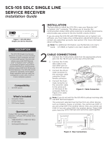
1. Introduction .................................................................1
System Overview ....................................................................................................2
Approvals ................................................................................................................3
Description (Hardware) ...........................................................................................5
Receiver Setup and Operation .................................................................................13
Description (Operation) ..........................................................................................14
2. SG-CPM3 Operating Modes ......................................17
Contrast Adjust .......................................................................................................18
Active Mode ............................................................................................................18
Manual Mode ..........................................................................................................18
Standby Mode .........................................................................................................19
System Trouble and System Information ................................................................19
AHS Table Management .........................................................................................19
3. Line Card ....................................................................20
Standby Mode .........................................................................................................21
Line Fault ................................................................................................................23
4. Programming/Operation .............................................27
Introduction .............................................................................................................28
Console Software ....................................................................................................28
Debug ......................................................................................................................28
Manual Programming .............................................................................................29
SG-CPM3 Options ..................................................................................................30
5. Advanced Programming ............................................45
SG-DRL3-2L/DRL3E System Options ..................................................................49
SG-DRL3/SG-DRL3-2L Static Options .................................................................51
SG-DRL3/SG-DRl3-2L Dynamic Options .............................................................63
6. SG-DRL3-IP Programming .......................................93
Options: 00 - 47 .......................................................................................................94
7. Printer Words ............................................................103
8. Telco Connector Pin Outs .........................................108
9. DEC-HEX-BIN Conversion Chart ............................112
10. ASCII Character Chart ............................................116
11. Communication Formats .........................................120
12. Ports ........................................................................122
Serial Printer Port (COM2) .....................................................................................123
RS-232 Serial Automation ......................................................................................123
13. Events & Messages .................................................124
14. Glossary ..................................................................135

GENERAL DESCRIPTION of the EQUIPMENT and CLASSIFICATION.
CLASSIFICATION
The SG-SYSTEM III equipment is a class 1, rack-mounted, (fixed-station-
ary) equipment, pluggable type A using a detachable power supply
cord, designed to be installed, operated and maintained by service per-
sonnel only - [persons having appropriate technical training and experience
necessary to be aware of hazards to which they are exposed in performing a task
and of measures to minimise the danger to themselves or other persons].
The equipment SG-SYSTEM III is designed to be installed in restricted
access locations within an environment that provides the Pollution Degree
max 2 and overvoltages category II - nonhazardous locations, indoor
only.
The power supply cord serves as a means of disconnection from the mains.
The outlet used to power the equipment shall be installed near the equipment
and shall be easily accessible. The equipment must be connected to a socket-
outlet with a protective earthing connection! The installation of the SG-
SYSTEM III equipment must provide a reliable earth connection and it shall
respect the local electrical wiring regulations.
IMPORTANT:
It is the responsibility of the installer to ensure that the SG-
SYSTEM III is properly mounted within a metallic fire enclosure with
a minimum thickness of 1.5 mm and the final assembly is compliant
with all of the applicable requirements from the point of view of the
accessibility to the energized parts (hazardous voltages, TNV circuits,
etc.) as these characteristics are defined within EN60950-1: 2006 stan-
dard.
The external enclosure shall meet all of the applicable requirements
from the point of view of physical requirements, e.g., steady force 250N,
impact and stability. The equipment must be secured to the building
structure before operation; all wiring and installation shall be in accor-
dance with electrical codes acceptable to the authorities that have juris-
diction where the equipment is installed, serviced and operated.
Not more than 3 (three) assemblies [each consisting of 2 (two) SG-SYS-
TEM III equipment] mounted within the same rack shall be powered
from the same branch circuit. Use a different branch circuit for any
group larger than 3 (three) assemblies.
The rack must be fixed in place; The subassemblies shall not be extended
away from the rack for installation and/or any other purpose.
Internal wiring shall be routed in a manner that prevents:
• excessive strain on wire and on terminal connections;
• loosening of terminal connections;
• damage of conductor insulation.
The wireways within the enclosure shall be smooth and free from sharp edges.
Wires shall be protected and routed so that they do not come in contact with
burrs, cooling fan or heatsinks which could cause damage to the insulation of
conductors. Holes in metal shall have smooth well-rounded surfaces or shall be
protected with bushings.
The external enclosure shall be connected to the protective earth ground.
The external cabinet (rack) must be secured to the building structure before
operation in a such a way to fully meet the stability requirements as per
EN60950-1: 2006 conditions.
An adequate marking, visible on the front of the door (cover), next to the
access door (or cover) of the rack, with instructions for protection once the
door (or covers) is (are) removed, stating that the “telephone cord is to be dis-
connected prior to opening the door” (or other acceptable marking), shall be
provided by the installer.
An acceptable power supply cord (detachable) shall be used in accordance with
the local outlets and voltages. It is the installer’s responsibility to provide
an appropriate acceptable power supply cord.
CAUTION:
This product uses lithium batteries. Improper handling of lithium batteries may
result in heat generation, explosion or fire, which may lead to personal inju-
ries.
Please ensure that the above precautions are strictly observed by the related divi-
sions including but not limited to sales, service, customers and (or) outside con-
tractors.
The equipment SG-SYSTEM III is equipped with lithium non replace-
able battery. Do not attempt to replace the battery.
CONNECTION TO THE MAINS
1. Connect first the detachable power supply cord to the IEC320 connec-
tor located on SG-SYSTEM III equipment.
2. Connect all the telecommunications cord-sets to the appropriate connec-
tors.
3. Ensure that the enclosure of the equipment SG-SYSTEM III is fully
installed (covers, doors, etc.) in a such a way that hazardous voltages
and TNV Circuits will not be accessible when the equipment is con-
nected to the mains and/or telecommunication network.
ATTENTION: The internal power supplies are not swappable. Discon-
nect power before attempting to change a power supply.
In order to change the internal Power Supply, first disconnect the detachable
power supply cord from the socket outlet used to provide power, and then,
from the IEC320 connector which is mounted on the SG-SYSTEM III equip-
ment. Wait minimum 5 seconds to allow the capacitor (C8) within the unit to
discharge. If the fuse is suspected of having opened, a discharge path for the
involved capacitor (C8) shall be provided.
Do not touch the heatsinks within the equipment: these are live parts and/or
may present a hazard related to high temperatures. In order to swap the boards
use the provided plastic handles (inserters, extractors).
No repairs in the field are allowed. The SG-System III equipment must
be returned to the manufacturer for repairs.


CHAPTER ONE - INTRODUCTION
2
SG-System I Operating Manual
1
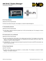
Figure 1-1, SG-System III
The SG-System III is a multi-platform receiver intended for remote monitoring of commercial fire and burglary systems.
The SG-System III equipped with SG-DRL3/SG-DRL3E/SG-DRL3-2L/SG-DRL3-IP can monitor up to 48 telephone lines, 24
IP communication line cards, or a combination of the two. The SG-System III time and date stamps all received alarm signals
which are then transmitted to a central station computer via TCP/IP or RS-232 port; transmitted directly to a printer using the
parallel printer port, RS-232 printer port and/or TCP/IP; and viewed on the LCD of the front panel while the receiver is in the
manual state. System configuration and phone line profiles can be programmed using a PC with SG-Systems Console or
locally using the scroll buttons and LCD. Each shelf can house up to 12 SG-DRL3, SG-DRL3E, SG-DRL3-2L or
SG-DRL3-IP in any combination.
System Overview
SG-DRL3/SG-DRL3E/SG-DRL3-2L
• Patented Caller Identification (Call Display) capability
• Patent pending AHS (Automatic Handshake selection)
• Patented virtual configurations
• Non-volatile memory on line cards for programming and event buffer
• Flash download for software upgrades for all supported line cards and the SG-CPM3
• DSP technology (patent pending)
• Up to 64 different options set (profiles per line card)
• Up to 8 different handshakes per profile
• Large, easy to read LCD (Liquid Crystal Display)
• All modules function individually to help ensure uninterrupted operation during hardware or software upgrades
• All cards are Hot Swappable. Cards can be removed and replaced without removing power from the system or compro-
mising the system performance
• 24 line cards maximum per redundant receiver
• 512-event memory buffer on each individual line card
• Real-time clock
• One parallel printer port, one serial printer port, one serial automation port and one ethernet (10/100BaseT) connection per
rack
• Events can be manually acknowledged by an operator.
• Programmable serial ports
• Continuous verification of the computer-receiver links with the 'heartbeat' function
• Fast transmission of multiple alarms to the computer and printer to ensure operator's quick response
• Telephone Line and Ethernet link supervision
• Rack mountable in standard 19 inch rack. For UL listed installations use IMRAK 1400 or other equivalent listed enclo-
sure.
DG009579

CHAPTER ONE - INTRODUCTION
3
SG-System I Operating Manual
1
SG-DRL3-IP
SG-DRL3-IP line card features include the following:
• Provides higher line security than conventional dial up panels with the polling feature.
• Quicker transmission since dialing or handshaking is not required.
• Network trouble detection is displayed on the LCD, printer and automation software.
• Static IP address for programming of the network protocols.
• Data network polling environment for replacement of an existing DVACS network. Meets the 90-second ULC require-
ment for this option.
• Ability to receive IP alarm messages from compatible communicators in either SIA or Contact ID.
• The T-LINK accounts and data encryption keys will be stored in the local line cards IP table.
NOTE: The SG-DRL3-IP can receive data from all DSC IP communicators. Please see the communicator manual for
compatibility limitations.
Approvals
Industry Approvals
• UL 1610 Central Station Burglar Alarm Units
• UL 864 Standard for Control Units and Accessories for Fire Alarm Systems
• CAN/ULC-S304:2016- REV 1 Control Units, Accessories and Receiving Equipment for Intrusion Alarm Systems.
• CAN/ULC-S559-13 Equipment for Fire Signal Receiving Centres and Systems
• FM approved
• EN60950-1:2006 Standard for Information Technology Equipment.
• AS/NZS 60950.1:2003 Information Technology Equipment - Safety
• CISPR22 Information Technology Equipment - Radio Disturbance Characteristics - Limits and Methods of Measure-
ments
• EN50130-4 Immunity requirements for components of fire, intruder and social alarm systems
This equipment shall be installed in accordance with the requirements of NFPA72, NFPA70, UL827 and the authority having
jurisdiction.
SG-System III with SG-DRL3-IP Line Card is ULC listed for active communication channel security level A1 - A4 when used
in conjunction with T-Link TL250 and T-Link TL300(CF), TL260(R), TL280LE(R), LE2080(R), TL280(R)E, TL880LT,
TL880LE, LE9080, 3G9080, HS3128/032/248, LE4010(CF), LE4020(CF), 3G4010(CF) Internet/Intranet and/or LTE/HSPA
alarm communicators. For this type of application the supervision and encryption features have to be enabled.
For ULC Installations the equipment shall be installed in accordance with the requirements of ULC-S561 and ULC-S301
Standards and the authority having jurisdiction.
For UL864 Commercial Fire applications, the following compatible communicators can be used with receiver model SG-Sys-
tem III SW Ver. 2.0x (using line card model SG-DRL3-IP SW Ver. 2.3x):
LE4010/LE4010CF SW Ver. 5.x
LE4020/LE4020CF SW Ver. 4.x
3G4010CF SW Ver. 4.x
TL300/TL300CF SW Ver. 1.5
The transmitter supervision (Option [13] in SG-DRL3-IP line card) shall be set to 60 minutes for single path and to 6 hours for
multiple path performance-based technologies.

CHAPTER ONE - INTRODUCTION
4
SG-System I Operating Manual
1
UL864 Programming Requirements
Table 1: UL864 Programming Requirements
NOTICE to Users, Installers, Authorities having Jurisdiction, and other involved parties
This product incorporates field programmable software. In order for the product to comply with the requirements in the
Standard for Control Units and Accessories for Fire Alarms Systems, UL 864, certain programming features or
options must be limited to specific values or not used at all as indicated below.
SG-CPM3
O p t # P r o g r a m O p t i o n P e r m i t t e d i n U L 8 6 4 ?
(Y/N)
Possible Settings Settings Permitted (UL
864)
12
13
16
17
18
19
1A
1B
1C
1D
1E
1F
20
21
22
23
24
25
26
27
28
29
2A
2B
2C
2D
Heartbeat Timer
Mute Buzzer
PSU 1 Mask
PSU 2 Mask
DCA 1 Mask
DCB 1 Mask
DCA 2 Mask
DCB 2 Mask
Reserved
Reserved
Fan 1 Mask
Fan 2 Mask
Mask UPS 1 AC
Mask UPS 1 Bat
Mask UPS 2 AC
Mask UPS 2 Bat
Mask SG TCP 1
Mask SG Serial 1
Mask SG TCP 2
Mask SG Serial 2
Mask TCP Printer 1
Mask Parallel 1
Mask SG Serial 1
Mask TCP Printer 2
Mask Parallel 2
Mask SG Serial 2
Y
N
N
N
N
N
N
N
N
N
N
N
N
N
N
N
N
N
N
N
N
N
N
N
N
N
00-FF
ON/OFF
ON/OFF
ON/OFF
ON/OFF
ON/OFF
ON/OFF
ON/OFF
ON/OFF
ON/OFF
ON/OFF
ON/OFF
ON/OFF
ON/OFF
ON/OFF
ON/OFF
ON/OFF
ON/OFF
ON/OFF
ON/OFF
ON/OFF
ON/OFF
ON/OFF
ON/OFF
ON/OFF
ON/OFF
Not allowed 00
OFF
OFF
OFF
OFF
OFF
OFF
OFF
OFF
OFF
OFF
OFF
OFF
OFF
OFF
OFF
OFF
OFF
OFF
OFF
OFF
OFF
OFF
OFF
OFF
OFF
SG-DRL3/SG-DRL3-2L
O p t # P r o g r a m O p t i o n P e r m i t t e d i n U L 8 6 4 ?
(Y/N)
Possible Settings Settings Permitted (UL
864)
04
1C
042
2F
7A
7B
7C
7D
2-Way Audio Activation Time
BUSY OUT (For SG-DRL3 only)
BUSY OUT (For SG-DRL3-2L only)
Online Time Out
4 and 5 Digit Account Codes to Activate
2-Way Audio
3-Digit Account Codes to Activate 2-Way
Audio
Alarm Codes to Activate 2-Way Audio
Audio Zone Code
Y
Y
Y
Y
Y
Y
Y
Y
00-FF
00-FF
00-FF
00-FF (00-255s)
00-FF
00-FF
00-FF
00-FF
00
00
00
00
00
00
00
00
Note: for Commercial Fire applications, a DACT shall automatically initiate and complete a test signal transmission
sequence to its associated receiver (SG-DRL3/SG-DRL3-2L line cards) at least once every 6 hours. The Automation
Software connected to the receiver at the supervising station will indicate the absence of the test transmission (change
settings from 24 hours to 6 hours).

CHAPTER ONE - INTRODUCTION
5
SG-System I Operating Manual
1
Parallel Printers
For UL and ULC Listed applications the following UL/ULC Listed printer can be used with the SG-System III:
• Seiko DPU-414
Serial Printers
For UL and ULC Listed applications the following UL/ULC Listed printer can be used with the SG-System III:
• Seiko DPU-414
NOTE: Do NOT use printer cables that have only 1 common ground wire.
UL Manual Mode
For UL manual mode, each event will activate the internal buzzer to be acknowledged manually. Each event will also be sent
automatically to the connected printer.
For Central Station applications, the signaling performance of each DACT (Digital Alarm Communication Transmitter) shall
be manually tracked. Failure to receive a signal from a DACT over 24 hour period shall be handled as a trouble signal.
Description (Hardware)
Basic Configuration: The basic configuration consists of one 19" rack mounted chassis comprising the following:
• SG-BP3 Backplane provides interconnection of modules and communications interface
• SG-CPM3 Module contains the CPU that controls all communication to and from up to 24 receiver modules, printers,
including 2 serial ports, a parallel port and an ethernet connection.
• SG-PSU3 Power Supply Unit provides power to all modules of the system.
• SG-DC/DC3 provides 5VDC power output required for the SG-DRL3 line cards. A slot exists for a second SG-DC/DC3
voltage converter. In the event of a failure, the redundant SG-DC/DC3 can be removed/replaced without powering down
the unit.
• SG-PSC3 (Power Supply Controller) monitors the states of the power and fan for each SG-MLRF3.
• SG-MLRF3: The metal rack of the SG-System III that incorporates the LCD and SG-BP3.
• SG-DRL3/DRL3E Line Card: Each SG-DRL3/DRL3E line card monitors one telephone line. Stores on the card up to 64
profiles for data management including 8 different handshaking protocols. Each card has a 512-event buffer.
• SG-DRL3-2L Line Card: Each SG-DRL3-2L line card monitors up to two telephone lines. Stores on the card up to 64
profiles for data management including 8 different handshaking protocols. Each card has a 512-event buffer.
•SG-DRL3-IP Line Card: Each SG-DRL3-IP line card supports up to 1536 IP transmitters and can supervise up to 512
transmitters. Each line card has a 512-event buffer.
SG-DRL3-IP
Opt# Program Option Permitted in UL 864?
(Y/N)
Possible Settings Settings Permitted (UL
864)
13
15
19
1A
1B
1C
1D
1E
1F
Transmitter Failure Debounce Time
Transmitter Restoral Debounce Time
Mask Transmitter Restoral
Mask Transmitter Failure
Mask Transmitter Swap
Mask Transmitter Unencrypted
Mask Invalid Report
Mask Unknown Account
Mask Supervised Acc Exceeded
Y
Y
N
N
N
N
N
N
N
5-65535
5-65535
OFF
OFF
OFF
OFF
OFF
OFF
OFF
3600 (1 h)/21600 (6 h)
300
OFF
OFF
OFF
OFF
OFF
OFF
OFF

CHAPTER ONE - INTRODUCTION
6
SG-System I Operating Manual
1
SG-BP3 Backplane
The SG-BP3 interconnects system modules and racks as well as providing communication outputs as indicated in figure 1-6.
Figure 1-2
SG-PSU3
Fan (not shown)
located above SG-PSU3
SG-DRL3XX
(12 cards per rack)
LCD
Line Card Debug Output
DG009562
SG-UIB3
SG-CPM3
SG-PSC3
SG-DC/DC3 B
SG-DC/DC3 A
USB
SG-PSU3 Power Supply Unit
The SG-PSU3 is the SG-System III power supply. The SG-System III requires a 120VAC/60Hz input power source. A power
cord with a IEC connector is required. The model SG-System III CE requires a 240VAC, 50Hz input power source.
NOTE: For UL/ULC installations use only 120VAC/60Hz to power the SG-System III.
For UL installations use UL listed UPS Power Supply for protective signaling systems and/or listed burglar alarm
power supply, as applicable.
The model SG-System III CE is not UL/ULC Listed.
Electrical Specifications:
SG-System III UL
• Input voltage range: 120VAC
• Frequency: 60Hz
• Input current: 2.5A max (RMS) @120VAC
SG-System III CE
• Input voltage range: 240VAC
• Frequency: 60Hz
• Input current: 2.5A max (RMS) @ 240VAC
In a 2-rack configuration, a redundant SG-PSU3 can be inserted in the second shelf. In the event of a SG-PSU3 failure, the
redundant SG-PSU3 automatically assumes operation. These modules are Hot Swappable (can be removed/replaced while the
system is in operation) if a working redundant SG-PSU3 is installed.
SG-CPM3 Central Processing Module
The SG-CPM3 Central Processing Module collects system information and directs line card information to the appropriate
outputs. Along with its built-in scroll buttons and large LCD message screen, the SG-CPM3 features TCP/IP, parallel printer
and two serial RS-232 ports for computer interface capability. The printer is supervised for loss of power, off-line, paper out
and other trouble conditions. The communication link to the automation computer through the RS-232 and TCP/IP port can be
monitored by the supervisory heartbeat transmissions.
Line Cards
The SG-System III supports a maximum of 24 line cards. Each line card is equipped with non-volatile memory to record
events. For each POTS card (SG-DRL3, SG-DRL3E and SG-DRL3-2L), calling source (Caller ID, ANI and calling name)
capability is built-in and telephone numbers can be printed out, sent to automation and stored in memory. Events and informa-

CHAPTER ONE - INTRODUCTION
7
SG-System I Operating Manual
1
tion stored in memory may be printed at any time. The SG-DRL3-2L and SG-DRL3E may perform flash updates over the
front edge USB port connection.
The SG-DRL3/SG-DRL3E/SG-DRL3-2L receives ANI (Automatic Number Identification) and/or DNIS (Dialed Number
Identification Service) via the Telco connection. This information allows the Sur-Gard System III to automatically change pro-
files for each received call. This eliminates dedicated line pool hardware. The DNIS information is used in a look-up table,
which sets up virtual line pools to identify security formats and extend account numbers. Standard DNIS is supported up to 10
digits. Each dialed number would have formerly been a line pool on conventional line cards.
The SG-DRL3-IP (UDP) Receiver Module functions as a LAN or WAN server to many remote clients (the transmitters). The
SG-DRL3-IP line card receives alarm events from the transmitter/panel decoding them before forwarding the signals to the
SG-CPM3 for subsequent output to the printer and automation outputs.
After a SG-DRL3-IP has been installed and configured, it will listen on a programmed port and await communications from
transmitters which have been configured to connect to that specific receiver. After communication has been established, the
transmitter will enter its normal operating mode (waiting for panel polls, transmit heartbeat signals, alarm messages and DLS/
SA download messages). The SG-DRL3-IP will log the connection and generate the appropriate event which will be for-
warded to the SG-CPM3. The SG-DRL3IP also features flash downloads through Ethernet for fast software upgrades.
When an alarm message is generated by the transmitter, it will send the message in a UDP/IP frame and transmit it to the
receiver (this communication can be optionally encrypted - reference transmitter documentation to determine if encryption is
supported by the device). When an alarm message is received from the transmitter/panel, the receiver will strip off the UDP
frame and decrypt the message. It will then send an appropriate response (ACK or NAK) back to the transmitter/panel. The
timing will follow the standard timing requirements of the panel. If the message was a valid alarm event, the event will be sent
to the appropriate connected printer and automation devices.
The SG-DRL3-IP line card receives heartbeats from all network supervision enabled transmitters periodically. This allows the
receiver to determine whether the transmitters are still online. The receiver maintains a table of all installed transmitters and
monitors their status (presence/absence, installed software versions, MAC addresses for swap detection purposes, and other
network statistics).
The SG-DRL3-IP line card can be programmed with various configuration parameters and options, including receiver IP
address, sub net mask, and default gateway address. Configuration parameters are password protected. The default password
can be changed for maximum security.
The SG-DRL3-IP line card is programmed with a globally unique MAC address during production. This MAC address is
NOT re-programmable.
NOTE:
Each SG-DRL3-IP Receiver Module can monitor up to a maximum of 1536 accounts of which 512 accounts
can be supervised.
SG-BP3X Interface Module
(One required per rack if SG-DRL3, SG-DRL3E, or DRL3-2L are used)
This 19” Rack-mounted panel interfaces with the SG-System III Telco connector to provide 24 RJ-11 connectors for direct
connection to telephone lines.
NOTE:
SG-DRL3/SG-DRL3E: On the BP3X, the B ports are the channels used for 2-way audio or back-up telephone line.
SG-DRL3-2L: On the BP3X the B ports are the channels used for channel 2 of the line card.
Figure 1-3 Front
• Connections for Redundant SG-System III: Refer to Figure 1-7 SG-System III Redundancy Wiring Diagram.
• Line Card Debug Output: Connect the RJ-45 end of the debug cable to the debug output jack.
Connect the female DB-9 connector to the serial port of a computer (COM1 port - DB-9 male).

CHAPTER ONE - INTRODUCTION
8
SG-System I Operating Manual
1
Figure 1-4 SG-CPM3 Debug Cable
54321
8
976
RJ45
Back of DB9
1 2 3 4 5 6 7 8
Pin 2 to Pin 5
Pin 5 to Pin 3
Pin 6 to Pin 2
• SG-DRL3 Debug Output: Connect the RJ-45 end of the debug cable to the debug output jack on the front of the line card.
Connect the female DB-9 connector to the serial port of a computer (COM1 port - DB-9 male).
Figure 1-5 SG-DRL3 Debug Cable
12345
7
689
RJ45
Back of DB9
1 2 3 4 5 6 7 8
Pin 3 to Pin 2
Pin 4 to Pin 3
Pin 5 to Pin 5
• IEC Power Connector: Provides local power line connection (cable is not supplied).
Figure 1-6, SG-System III Wiring Diagram
DB25
Parallel
Printer
Output
Not
Used
SG-CPM3
Debug
Output
IEC Power
Connector
120Vac / 60 Hz*
2.5A
AC Input circuit
non power limited
RS-232
Serial
Printer
Output
Ethernet**
Output
10/100 BaseT
25 Pair RJ-21 Supervised Telephone Lines
(Refer to Appendix C for pin out)
12 RJ-45
Connectors
Not Used
Shelf
Address
Switch
12 RJ-45 jacks for
IP connectivity for
SG-DRL3-IP cards
RS-232
Serial
Automation
Output
* For Model System III CE:
- 240V
AC /50Hz
- System III CE is not UL Listed
**CAUTION: The Ethernet
communication lines must be
connected first to an approved
(acceptable to the local
authorities) type NID (Network
Interface Device) before
leaving the premises (e.g., UL
installations, UL60950 Listed
NID).
Connections for second
backplane (Refer to Figure 1-7)
See System III Supervised
UPS Connection diagram for
details (Refer to Figure 1-8)
Note: For UL Installations:
- AC input is 120V / 60 Hz.
- Do not connect to a receptacle
controlled by a switch.
Notes:
1. All external devices should be mounted in
the same room as the receiver.
2. All circuits are power limited except AC input.
3. Maintain 6.5 mm (1/4") separation between
power limited and non-power limited circuits.
All outputs supervised
DG009582
WAR NIN G: To reduce the risk of electric shock the product is provided with a grounding type power supply IEC
receptacle. Connect product using an appropriate IEC cable to a grounded receptacle.
• RS-232 Serial Automation Output: Provides serial connection to a local computer running automation software. A null
modem serial cable must be used.

CHAPTER ONE - INTRODUCTION
9
SG-System I Operating Manual
1
• RS-232 Serial Printer Output: Provides serial connection to a local computer or serial printer. A null modem serial cable
must be used.
• 25 Pair Telco Connection: Connects directly to the local PBX or to SG-BP3X (Refer to Appendix B for pinouts).
• Ethernet Output 10/100 BaseT: Traditional automation communication is provided via port 1025 on the Ethernet connec-
tion. This primary port is a Sur-Gard standard output and provides Sur-Gard standard automation protocol output. All or a
number of virtual receiver types can be mapped to the Sur-Gard output.
CAUTION: The Ethernet communication lines must be connected first to an approved (acceptable to the local authorities)
type NID (Network Interface Device) before leaving the premises (e.g., UL installations, UL60950 Listed NID).
Figure 1-7, SG-System III Redundancy Wiring Diagram
0
1
2
3
4
5
8
6
7
9
A
B
D
C
E
F
0
1
2
3
4
5
8
6
7
9
A
B
D
C
E
F
Shelf 2
Shelf 1
0
1
2
3
4
5
8
6
7
9
A
B
D
C
E
F
All circuits are power limited
Use only the cables provided in the
SG-System III Interconnect Pack. Failure
to do so may result in damage to the unit.
Using the provided RJ-45 patch cables,
connect the Output of the primary
SG-System III (shelf address 1) to the
Input of the secondary System III (shelf
address 2). Connect the Output of the
secondary SG-System III to the Input of
the primary SG-System III.
Use a small flat screwdriver to
turn the shelf address switch to 2
on the secondary SG-System III.
Switch Setting
Speed
(Printer and Automation)
Shelf
1 57,600 1
2 57,600 2
5 520,000 1
6 520,000 2

CHAPTER ONE - INTRODUCTION
10
SG-System I Operating Manual
1
Figure 1-8, SG-System III UPS Supervision Connection Diagram
0
1
2
3
4
5
8
6
7
9
A
B
D
C
E
F
UPS LOW BAT Normally Closed
Common
UPS AC TROUBLE Normally Closed
Note:
UPS connection is to
be made using dry
contact connections
provided by the UPS.
12V , 25mA
DC
UPS
SG-System III Backplane
AC In
AC Out
In2
In1
COM
IEC Power
Connector
EGND
For UL Installation of model SG-System III: UPS Output 120V /60Hz, 2.5A
For model SG-System III CE (not UL Listed): UPS Output 240V
AC
/50Hz
AC
For UL/ULC installations use a UL listed UPS
(Uninterruptible Power Supply) for
protective-signaling systems and/or listed burglary
alarm power supply, as applicable.
For ULC Installations, the equipment shall be rack
mounted and energized by a permanently wired
supply in accordance with C22.1, Canadian Electri-
cal Code, Part 1, Safety Standard for Electrical
Installations, section 32.
Connection to a UPS (Uninterruptible Power
Supply) with minimum 24 hour standby capability is
required.
WAR NIN G: To reduce the risk of electrical shock, the product is provided with a grounding type power supply IEC
receptacle. Connect product using an appropriate IEC cable to a grounded receptacle.
NA: Not allowed
Table 2: Loading Capacities for Hunt Groups
Number of Lines in Hunt Group
System Loading at the Supervising Station 12345-8
Number of initiating circuits NA 5,000 10,000 20,000 20,000
Number of DACTs NA 500 1,500 3,000 3,000
With DACR lines processed serially (put on hold, then answered one at
a time)
Number of initiating circuits NA 3,000 5,000 6,000 6,000
Number of DACTs NA 300 800 1,000 1,000

CHAPTER ONE - INTRODUCTION
11
SG-System I Operating Manual
1
Figure 1-9, SG-System III Power Limited Circuit Separation from Non-Power Limited Circuit Diagram
Serial
Automation
Serial
Printer
TCP
Connection
DRL3-IP
Network Connection
Serial
Automation
Serial
Printer
TCP
Connection
DRL3-IP
Network Connection
Power Cord
(Refer to the Note)
Power Cord
(Refer to the Note)
Parallel
Printer
Parallel
Printer
NOTE: The power cord needs to be
routed ¼ inch away from all other cables
coming from or which are part of the
SG-System III.
Receiver Setup and Operation
Sur-Gard recommends testing the receiver before actual installation. Becoming familiar with the connections and setup of the
unit on the workbench will make final installation more straightforward.
The following items are required:

CHAPTER ONE - INTRODUCTION
12
SG-System I Operating Manual
1
• IEC power supply cord
• One telephone line
• One or more dialer or digital control panel(s)
1. Unpack the components for the SG-System III.
NOTE: Carefully unpack the receiver and inspect for shipping damage. If there is any apparent damage, notify the
carrier immediately.
2. Unscrew the front thumb screws and open the front plates.
NOTE: Before inserting the SG-CPM3, connect the ribbon cable from the SG-UIB3 board. Before inserting the SG-
PSC3 connect the LCD power cable.
3. Starting with slot 1, insert all cards in the rack to their appropriate positions. Ensure that there are no open slots between
cards. (refer to figure 1-2).
4. Insert the SG-PSU3 into the rack and screw in the thumb screw.
5. Connect a telephone line to the corresponding line on the SG-BP3.
6. Connect the main power using a standard computer IEC cable (not supplied).
7. The LCD will power up and display internal troubles (e.g., printer, computer, telephone line fault). The SG-DRL3 that has
the telephone line connected to it will have its red LED off. If the LED is on, make sure the telephone line is connected to
the correct port.
8. Press the ACK button until all of the initial signals have been acknowledged (ACK button has stopped flashing and the
buzzer has been silenced).
NOTE: Internal diagnostics may require more than one minute during the power up sequence.
9. Send a signal from a control panel to the receiver. The signal will be displayed on the LCD. Press the [ACK] button to
silence the buzzer and clear the signal from the LCD.
Description (Operation)
Operation with Default Programming
Without any changes to the factory default programming, the receiver operates as indicated below:
• Answers incoming calls on the first ring
• Sends the following handshake order:
• Receives most communication formats, except for 3/2, 3/1 checksum, SKFSK, 4/2 extended, and 4/2 checksum (see
Option 95).
• The above formats can be manually selected
• Signals can be displayed on the debug output computer as they are received. The signals are then sent to the printer and
computer connected to serial port COM1 or to the 10/100BaseT. The default event codes described in the SG-DRL3
Library Decoding and Event Codes Table will be used with the Sur-Gard automation communication protocol to send sig-
nals to the computer, if connected.
• If a computer is not connected press the [ACK] button on the SG-CPM3 to silence the buzzer and to clear the alarm(s)
from the LCD display.
1
2
3
4
5
6
2300 Hz
1400 Hz
Dual-tone
SIA FSK
ITI, Modem IIE/IIIa2
Modem II

CHAPTER ONE - INTRODUCTION
13
SG-System I Operating Manual
1
Virtual Connectivity
Each SG-CPM3 has one static IP address and a number of associated ports. The configuration management, done from the
Console Software, is located on port 1024. The SG-Systems Console software is provided for Microsoft Windows operating
system (refer to the console documentation for compatibility listing), which provides a graphical style menu for configuration
management. Additional features are available with the SG-Systems Console software including storage of virtual receiver
setups and configuration wizards.
Status Addressing
Line card status is reported via physical addressing. Shelf and slot number are assigned automatically to each line card. All
device status information is in Sur-Gard format. The reporting of status on this port, automation output and printer will relate
to physical addressing.
Automation Input/Output (Port 1025)
Traditional automation communication is provided via port 1025 on the Ethernet connection. This primary port is a Sur-Gard
standard output and provides Sur-Gard standard automation output.
Compatibility
Central station automation software packages such as:
• MAS • DICE • SIMS II • GENESYS
• S.I.S. • IBS • MicroKey • Bold
support the SG-System III Sur-Gard interface. Refer to automation software specifications for compatibility.
NOTE: Automation connections are considered supplementary per UL864 Listing. Compatibility with the automa-
tion software in a system used at a central station is intended to be handled under a separate UL1981 software and/or
site certification evaluation.
Automation Protocols
The SG-System III receiver sends a variety of protocols to report signals to the central station computer via a TCP/IP and/or
RS-232 port. A complete list of protocols is listed in Appendix E.
Data Byte Protocol
The SG-System III receiver uses a default configuration of 9600 Baud rate, 1-start bit, 8-data bits, 0-parity bits and 2-stop bits
structure, to transmit and receive signals on the RS-232 port. This protocol can be programmed on the receiver to enable dif-
ferent configurations.
Acknowledgment of the Signal
The SG-System III receiver requires an acknowledgment signal [ACK] (Hex 06) from the computer software within 4 seconds
for each message sent. Failure to receive the [ACK] will result in retransmission of the signal. After the fourth attempt, the
SG-System III will indicate a communication failure on with the automation port. During a communication failure the SG-Sys-
tem III receiver will stop transmitting except for the heartbeat. In case of communication failure with the computer, the
SG-System III receiver can store up to 512 events in its internal memory. Communication is resumed when the first heartbeat
acknowledgment is received; all buffered information is then transmitted.
COM Responses
When the SG-CPM3 sends an event to the computer, it checks for 3 responses: ACK, NAK or Unknown/No Response. An
ACK indicates that the computer automation received the event successfully. A NAK indicates the computer automation
received the message but didn't understand it. The line card will attempt to send the messages 25 times. If after the 25th

CHAPTER ONE - INTRODUCTION
14
SG-System I Operating Manual
1
attempt it receives a NAK from the computer automation, the SG-DRL3 will generate an internal communication error. After
20 NAKs the SG-CPM3 will send an internal communication error event to the printer and output the message to the printer in
ASCII and attempt to move onto the next signal. Any other response from the computer automation, including no response will
cause the SG-CPM3 to attempt to send the message again, up to 4 times. If after 4 attempts the SG-CPM3 does not receive a
response or receives an unknown response, it will assume nothing is connected, generate an alarm and fall to the next active
automaton port or manual mode.
Automation Absent
When the computer is not responding to transmissions, the SG-CPM3 will generate a 'SG-Serialx fail' or 'SG-TCP/IPx Fail'
trouble. When the trouble occurs, the SG-CPM3 will continue to attempt to send a heartbeat signal to the computer until it gets
a response. The SG-System III receiver will make 4 attempts, then wait for the next heartbeat period before making another 4
attempts. The typical heartbeat interval is 30 seconds.
This signal is used to supervise the communication between the receiver and computer automation. It is sent to the computer
automation every 30 seconds and is programmable from the receiver. The computer automation should acknowledge this sig-
nal with an [ACK]. The SG-CPM3 can be programmed to send a heartbeat signal to the computer automation once every 01-
99 seconds to test the connection between the SG-CPM3 and the computer automation (30 seconds is recommended). If a
heartbeat fails to get a response from the computer automation, the SG-CPM3 will immediately transmit the heartbeat again,
up to 4 attempts. The SG-System III, by default, will output the automation signals via TCP/IP. If TCP/IP fails it will switch to
the Serial Automation output.
If the serial output fails, the SG-CPM3 will switch to manual mode, all signals will be displayed on the LCD and will require a
manual acknowledgement. To re-establish connection with the TCP/IP a reset SG fall-back command must be generated from
the Console software. If the line card buffers are full, the line cards will stop answering calls.
SG-System III SIA Internal Status Output
Supervisory Heartbeat Signal Protocol (1)
100000sssssssssss@ssss[DC4]
00000 Receiver number (First two digits are pro-
grammed section [14] of the CMP3. The
remaining digits are always zeros).
s Space Character.
@ Supervisory Signal.
[DC4] Terminator, 14 Hex
0RRLLL[#0000|NYYZZZZ]
0 Protocol ID
RR Receiver number of the SG-CPM3
LLL Line card number, 000 signifies a SG-CPM3
Event.
0000 SG-System III account.
NYYZZ SIA Event
[DC4] Terminator, 14 Hex


CHAPTER TWO - SG-CPM3 OPERATING MODES
18
SG-System I Operating Manual
2
Contrast Adjust
Press the Up and Enter buttons together to increase the contrast or press Down and Enter together to decrease the contrast. This operation
can be done at any time after the power up sequence.
Active Mode
In Active mode, the primary connection to the computer is via TCP/IP networking on the 10/100 BaseT Ethernet connection for the automa-
tion computer. If this fails, then the output will go via serial RS-232. A command can then be sent through the SG-Systems Console software
to revert back to TCP/IP when the connection is restored. The IP of the SG-CPM3 is displayed on the screen.
Figure 2-1, Active Mode
SG-SYSTEM III v2.00.01.015 (Shelf 1)SG-SYSTEM III v2.00.01.015 (Shelf 1)
SG-SERIALSG-SERIAL
ACTIVE
12 Linecard(s) (Shelf 1)12 Linecard(s) (Shelf 1)
05 Linecard(s) (Shelf 2)05 Linecard(s) (Shelf 2)
Automation IP: 30.0.25.16Automation IP: 30.0.25.16
Console IP: 30.0.25.26Console IP: 30.0.25.26
Printer IP: 30.0.25.26Printer IP: 30.0.25.26
User Dene LCD Message Line 1User Dene LCD Message Line 1
User Dene LCD Message Line 2User Dene LCD Message Line 2
IP: 30.0.21.112IP: 30.0.21.112
Nov-29-2010 08:18:04Nov-29-2010 08:18:04
SYSTEM OK
DG009574
SUR-GARD
Manual Mode
For Manual mode, each event will activate the internal buzzer to be acknowledged manually. Each event will be sent automatically to the
connected printer and displayed on the SG-CPM3 LCD. Messages longer than 80 characters will be displayed on two lines. Once the signal
is acknowledged, it will be cleared from the screen.
Figure 2-2, Manual Mode
Alarm Buer (0000, 0006)Alarm Buer (0000, 0006)
MANUAL
01/00-0000-NSC0000-Switching To Manual Mo01/00-0000-NSC0000-Switching To Manual Mo
dede
02/02/-0000-01-PER TEST REPORT02/02/-0000-01-PER TEST REPORT
02/01-1234--Nril/R00102/01-1234--Nril/R001
02/01-0000-02-PER TEST REPORT02/01-0000-02-PER TEST REPORT
02/02-0000-03-PER TEST REPORT02/02-0000-03-PER TEST REPORT
02/01-1112-38-BURGLARY02/01-1112-38-BURGLARY
IP: 30.0.21.112IP: 30.0.21.112
Nov-17-2011 09:46:04Nov-17-2011 09:46:04
SYSTEM OK
DG009577
SUR-GARD
NOTE: The SG-CPM3 will display a maximum of 5000 events which have not been acknowledged.
/