2. COMPLIANCE WITH CE MARKING
2.1 What is CE marking?
The CE marking is mandatory and must be affixed to specific products placed on the European
Union. When a product conforms to the requirements, the CE marking must be affixed to the
product. The CE marking also applies to machines and equipment incorporating servos. When you
need a copy of Declaration of Conformity of CE marking, contact your local sales office.
(1) EMC directive
The EMC directive applies to the servo units alone. This servo is designed to comply with the
EMC directive. The EMC directive also applies the servo-incorporated machines and equipment.
This requires the EMC filters to be used with the servo-incorporated machines and equipment
to comply with the EMC directive. For specific EMC directive conforming methods, refer to the
EMC Installation Guidelines (IB(NA)67310).
(2) Low voltage directive
The low voltage directive applies also to servo units alone. This servo is designed to comply with
the low voltage directive.
2.2 For compliance
Be sure to perform an appearance inspection of every unit before installation. In addition, have a
final performance inspection on the entire machine/system, and keep the inspection record.
(1) Drive unit , interface unit , base unit and servo motors used
Use the drive unit , interface unit , base unit and servo motors which standard product.
Drive unit :MR-J2M--- DU
Interface unit :MR-J2M-P8
Base unit :MR-J2M- BU
Servo motor :HC-KFS
HC-MFS
HC-UFS
(2) Structure
Reinforced
insulating
transformer
MCCB
MC M
Molded-case
circuit breaker
Magnetic
contactor
Reinforced
insulating type
24VDC
power
supply
MELSERVO
-J2M
Servo
motor
Control box
(3) Environment
Operate MELSERVO-J2M at or above Pollution degree 2 set forth in EN664-1. For this purpose,
install MELSERVO-J2M in a control box which is protected against water, oil, carbon, dust, dirt,
etc. (IP54).
(4) Power supply
(a) Operate MELSERVO-J2M to meet the requirements of the overvoltage category II set forth
in EN664-1. For this purpose, a reinforced insulating transformer conforming to the EN
Standard should be used in the power input section.
(b) When supplying interface power from external, use a 24VDC power supply which has been
insulation-reinforced in I/O.
(5) Grounding
(a) To prevent an electric shock, the protective earth (PE) terminal (marked ) of the base unit
must be connected to the protective earth (PE) of the control box.
(b) Do not connect two ground cables to the same protective earth (PE) terminal. Always connect
cables to the terminals one-to-one.
(c) If an earth leakage circuit breaker is used, always earth the protective earth (PE) terminal of
the base unit to prevent an electric shock.
(6) Peripheral devices, options
(a) Use the molded-case circuit breaker and magnetic contactor models which are EN/IEC
Standard-compliant products given in the MELSERVO-J2M Instruction Manual.
(b) The sizes of the wires given in the MELSERVO-J2M Instruction Manual meet the following
conditions. For use in any other conditions, follow Table 5 and Annex C of EN60204-1.
Ambient temperature : 40
(104 )
Sheath : PVC (polyvinyl chloride)
Installation on wall surface or open cable tray
(c) Use the EMC filter for noise reduction.
(d) The protective earth (PE) of the servo motor is connected with the protective earth (PE) of
the base unit via the screw which fixes the drive unit to the base unit. Therefore, please
tighten the screw surely and fix the drive unit to the base unit.
(7) Performing EMC tests
When EMC tests are run on a machine/device into which MELSERVO-J2M has been installed,
it must conform to the electromagnetic compatibility (immunity/emission) standards after it has
satisfied the operating environment/electrical equipment specifications. For the other EMC
directive guidelines on MELSERVO-J2M, refer to the EMC Installation
Guidelines(IB(NA)67310).
- MR-J2M Series are not intended to be used on a low-voltage public network which supplies
domestic premises;
- radio frequency interference is expected if used on such a network.
The installer shall provide a guide for Installation and use, including recommended mitigation
devices.
3. CONFORMANCE WITH UL/cUL STANDARD
MELSERVO-J2M has suited UL508C.
(1) Drive unit , interface unit , base unit and servo motors used
Use the drive unit , interface unit , base unit and servo motors which standard product.
Drive unit :MR-J2M---
DU
Interface unit :MR-J2M-P8
Base unit :MR-J2M- BU
Servo motor :HC-KFS
HC-MFS
HC-UFS
(2) Installation
The MR-J2M series have been approved as the products which have been installed in the
electrical enclosure. The minimum enclosure size is based on 150 of each MR-J3 combination.
And also, design the enclosure so that the ambient temperature in the enclosure is 55˚C
(131˚F ) or less. The drive unit must be installed in the metal cabinet. For environment, the
units should be used in open type (UL 50) and overvoltage category II or lower. The
converter unit and servo amplifier (drive unit) need to be installed at or below of pollution
degree 2. For connection, use copper wires.
(3) Short-circuit current rating (SCCR)
Suitable For Use On A Circuit Capable Of Delivering Not More Than 100 kA rms Symmetrical
Amperes, 500 Volts Maximum.
(4) Flange
Mount the servo motor on a flange which has the following size or produces an equivalent or
higher heat dissipation effect.
Servo motor
Flange size
[mm(in)]
HC-KFS HC-MFS HC-UFS
150 150 6
(5.91 5.91 0.24)
053 13 053 13 13
250 250 6
(9.84 9.84 0.24)
23 23 23
250 250 12
(9.84 9.84 0.47)
43 43 43
300 300 12
(11.81 11.81 0.47)
73 73 73
(5) Capacitor discharge time
The capacitor discharge time is as follows. To ensure safety, do not touch the charging section
for 15 minutes after power-off.
Base unit Discharge time (min)
MR-J2M-BU4 1
MR-J2M-BU6 1
MR-J2M-BU8 1
(6) Options, peripheral devices
Use the UL/cUL Standard-compliant products.
Use the following molded-case circuit breaker and fuse.
(a) Molded-case circuit breaker
Servo motor output total
Molded-case
circuit breaker
Rated current [A]
550W max. 30A frame5A 5
More than 550W to 1100W max. 30A frame10A 10
More than 1100W to 1650W max. 30A frame15A 15
More than 1650W to 2200W max. 30A frame20A 20
More than 2200W to 3300W max. 30A frame30A 30
(b) Fuse
Fuse
Servo motor output total
Class Current [A] Voltage [V]
800W max. K5 15 AC250
More than 800W to 1100W max. K5 20 AC250
More than 1100W to 1650W max. K5 30 AC250
More than 1650W to 2200W max. K5 40 AC250
More than 2200W to 3300W max. K5 70 AC250
(7) Selection example of wires
To comply with the UL/cUL Standard, use UL-approved copper wires rated at 60/75
(140/167
)
for wiring.
(Note 1) Crimping terminals, crimping tools
Unit
L1 L2 L3 L11 L21 UV W PC B1 B2
MR-J2M-BU4 2(AWG14)
MR-J2M-BU6 3.5(AWG12)
MR-J2M-BU8 5.5(AWG10)
2(AWG14) 2(AWG14)
MR-J2M-10DU
MR-J2M-20DU
MR-J2M-40DU
MR-J2M-70DU
1.25(AWG16) 1.25(AWG16)
(8) About wiring protection
For installation in United States, branch circuit protection must be provided, in accordance with
the National Electrical Code and any applicable local codes.
For installation in Canada, branch circuit protection must be provided, in accordance with the
Canada Electrical Code and any applicable provincial codes.
(9) Overload Protection Characteristics
An electronic thermal relay is built in the drive unit to protect the servo motor and drive unit
from overloads. The operation characteristics of the electronic thermal relay are shown below. It
is recommended to use an unbalanced torque-generated machine, such as a vertical motion
shaft, so that unbalanced torque is not more than 70% of the rated torque.
MR-J2M series servo amplifiers have each solid-state servo motor overload protection. (The
motor full load current is 115% rated current.)
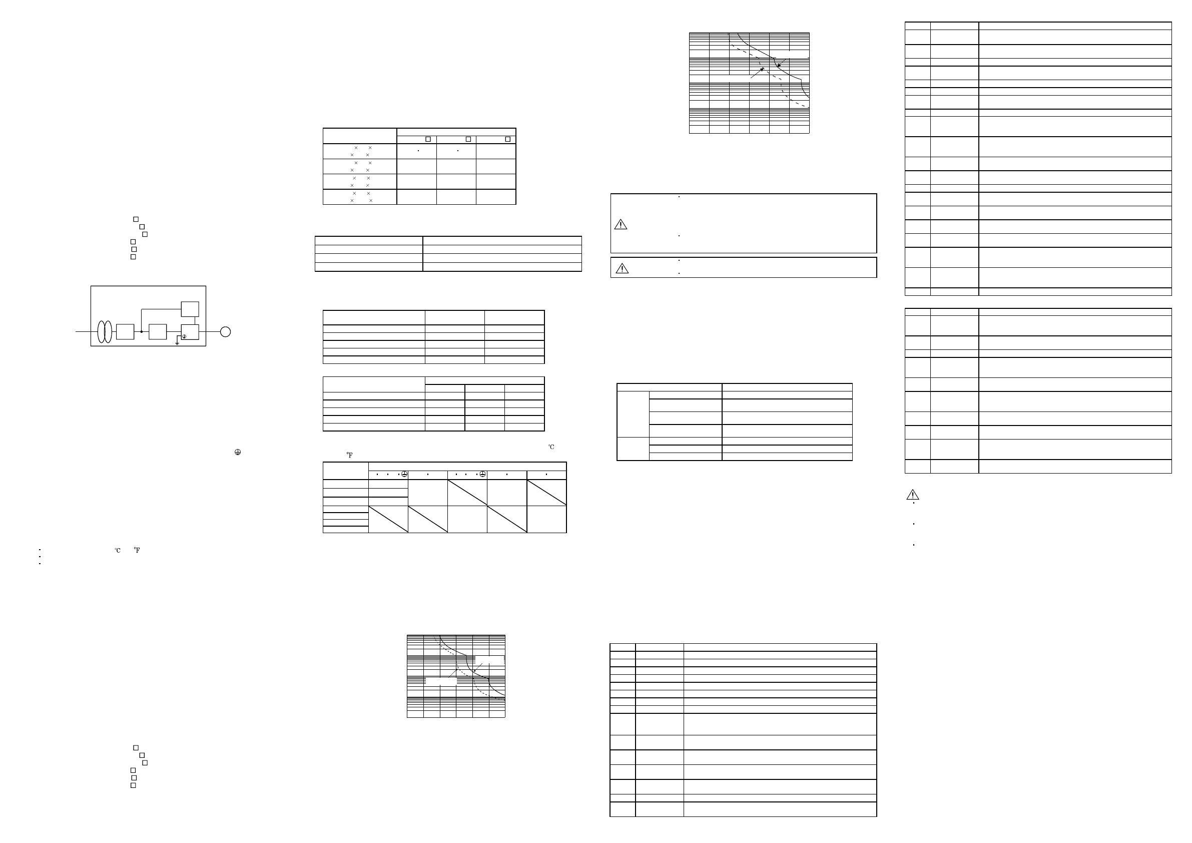
(a) MR-J2M-10DU to MR-J2M-40DU
1000
100
10
1
0.1
0 50 150 200 250 300
Load ratio [%]
100
Operation time [s]
In operation
In servo lock
(b) MR-J2M-70DU
1000
100
10
1
0.1
0 50 150 200 250 300100
Operation time [s]
Load ratio [%]
In operation
In servo lock
(10)Over-temperature protection for motor
Motor Over temperature sensing is not provided by the drive.
4. INSPECTION
WARNING
Before starting maintenance and/or inspection, turn off the power and
wait for 15 minutes or more until the charge lamp turns off. Then,
confirm that the voltage between P and N is safe with a voltage tester
and others. Otherwise, an electric shock may occur. In addition, always
confirm from the front of the interface unit whether the charge lamp is
off or not.
Any person who is involved in inspection should be fully competent to
do the work. Otherwise, you may get an electric shock. For repair and
parts replacement, contact your safes representative.
CAUTION
Do not test MELSERVO-J2M with a megger (measure insulation
resistance), or it may become faulty.
Do not disassemble and/or repair the equipment on customer side.
(1) Inspection
It is recommended to make the following checks periodically.
(a) Check the screw which fixes each unit. Retighten any loose screws.
(b) Check the servo motor bearings, brake section, etc. for unusual noise.
(c) Check the cables and the like for scratches and cracks. Perform periodic inspection according
to operating conditions.
(d) Check the servo motor shaft and coupling for misalignment.
(2) Life
The following parts must be changed periodically as listed below. If any part is found faulty, it
must be changed immediately even when it has not yet reached the end of its life, which
depends on the operating method and environmental conditions.
For use in the atmosphere having much oil mist, dust, etc., clean and inspect every three
months.
For parts replacement, please contact your sales representative.
Part name Standard life
Smoothing capacitor 10 years
Relay
Number of power-on and number of forced
stop times: 100,000 times
Cooling fan
10,000 to 30,000
hours (2 to 3 years)
Each unit
Absolute position
battery unit
Refer to MELSERVO-J2M Instruction
Manual.
Bearings 20,000 to 30,000 hours
Encoder 20,000 to 30,000 hours
Servo
motor
Oil seal, V ring 5,000 hours
(a) Smoothing capacitor
Affected by ripple currents, etc. and deteriorates in characteristic. The life of the capacitor
greatly depends on ambient temperature and operating conditions. The capacitor will reach
the end of its life in 10 years of continuous operation in normal air-conditioned environment.
(b) Relays
Their contacts will wear due to switching currents and contact faults occur. The relay
becomes longevity by the power supply turning on frequency and 100,000 times of the forced
stop frequency. However, this value changes by the difference of the power supply capacity.
(c) Drive unit cooling fan
The cooling fan bearings reach the end of their life in 10,000 to 30,000 hours. Normally,
therefore, the fan must be changed in a few years of continuous operation as a guideline.
It must also be changed if unusual noise or vibration is found during inspection.
(d) Servo motor bearings
When the servo motor is run at rated speed under rated load, change the bearings in 20,000
to 30,000 hours as a guideline. This differs on the operating conditions. The bearings must
also be changed if unusual noise or vibration is found during inspection.
(e) Servo motor oil seal, V ring
Must be changed in 5,000 hours of operation at rated speed as a guideline. This differs on the
operating conditions. These parts must also be changed if oil leakage, etc. is found during
inspection.
5. ALARMS AND WARNINGS
5.1 Alarms
Indication Name Definition
A.10 Under voltage Power supply voltage dropped to 160V or less.
A.12 Memory error 1 RAM memory fault
A.13 Clock error Printed board fault
A.14 Watchdog CPU/parts fault
A.15 Memory error 2 EEP-ROM fault
A.16 Encoder error 1 Communication error occurred between encoder and drive unit.
A.17 Board error 2 CPU/parts fault
A.19 Memory error 3 ROM memory alarm
A.1A
Motor
combination
error
Wrong combination of drive unit and servo motor.
A.1B. Axis set error
The axis number of the drive unit set up in the same base unit
overlaps
A.1C
The base unit
bus error 1
Abnormality is found in the communication between the interface unit
and the drive unit.
A.1D
The base unit
bus error 2
Abnormality is found in the communication between the interface unit
and the drive unit.
A.1E
The drive unit
mounting error
The drive unit came off from the base unit after the initializing.
A.20 Encoder error 2 Communication error occurred between encoder and drive unit.
A.24
Main circuit
error
Ground fault occurred at the servo motor outputs (U,V and W phases)
of the drive unit.
Indication Name Definition
A.25
Absolute
position erase
Absolute position data in error. Power was switched on for the first
time in absolute position detection system.
A.30
Regenerative
error
Permissible regenerative power of the built-in regenerative resistor or
regenerative option is exceeded.
A.31 Overspeed Speed has exceeded the instantaneous permissible speed.
A.32 Overcurrent
Current that flew is higher than the permissible current of the drive
unit.
A.33 Overvoltage Converter bus voltage exceeded 400V.
A.34 CRC error CRC alarm command cable fault
A.35
Command
frequency error
Input pulse frequency is too high.
A.36 Transfer error Bus cable/Printed board fault
A.37
IFU parameter
error / DRU
parameter error
A set value of the IFU parameter or the DRU parameter is abnormal.
A.38
DRU parameter
adjustment
error
There is a drive unit which sets a value different by the parameter
which should set all axes in the same value.
A.45
Main circuit
device overheat
Main circuit device overheat
A.46
Servo motor
overheat
Servo motor temperature rise actuated the thermal protector.
A.50 Overload 1 Load exceeded overload protection characteristic of drive unit.
A.51 Overload 2
Machine collision or the like caused max. output current to flow
successively for several seconds.
A.52 Error excessive
Droop pulse value of the deviation counter exceeded the parameter
No.31 setting value (initial value: 8 revolutions).
A.53
Multiple spindle
overload
The drive unit of 85% in the regenerative load ratio is adjacent on the
base unit.
A.54
Drive unit
alarm
The alarm was generated in one drive unit or more set up in the base
unit.
A.8A
Serial
communication
time-out
Serial communication stopped for longer than the time set in IFU
parameter No.56.
A.8E
Serial
communication
error
Serial communication error occurred between interface unit and
communication device (e.g. personal computer).
88888 Watchdog CPU, parts faulty
5.2 Warnings
Indication Name Definition
A.92
Battery cable
disconnection
warning
Voltage of battery unit for absolute position detection system reduced.
A.96
Zero setting
warning
Home position setting failed.
A.9F Battery warning Voltage of battery unit for absolute position detection system reduced.
A.E0
Excessive
regenerative
warning
There is a possibility that regenerative power may exceed permissible
regenerative power of built-in regenerative resistor or regenerative
option.
A.E1
Overload
warning
There is a possibility that overload alarm 1 or 2 may occur.
A.E3
Absolute
position counter
warning
Absolute position encoder pulses faulty.
A.E4
Parameter
Warning
Parameter outside setting range
A.E6
Servo forced
stop warning
EM1-EM2 are open.
A.E7
Controller
emergency stop
warning
Emergency stop command was received from servo system controller.
A.E9
Main circuit off
warning
Servo was switched on with main circuit power off.
FOR MAXIMUM SAFETY
These products have been manufactured as a general-purpose part for general industries, and
have not been designed or manufactured to be incorporated in a device or system used in
purposes related to human life.
Before using the products for special purposes such as nuclear power, electric power,
aerospace, medicine, passenger movement vehicles or under water relays, contact your local
sales office.
These products have been manufactured under strict quality control. However, when
installing the product where major accidents or losses could occur if the product fails, install
appropriate backup or failsafe functions in the system.
Precautions for Choosing the Products
Mitsubishi will not be held liable for damage caused by factors found not to be the cause of
Mitsubishi; machine damage or lost profits caused by faults in the Mitsubishi products;
damage, secondary damage, accident compensation caused by special factors unpredictable by
Mitsubishi; damages to products other than Mitsubishi products; and to other duties.


