(1) Servo amplifiers and servo motors used
Use the servo amplifiers and servo motors which standard product.
Servo amplifier series :MR-E-10 to MR-E-200
Servo motor series :HF-KE
HF-SE
(2) Structure
Reinforced
insulating
transformer
MCCB MC M
Molded-case
circuit breaker
Magnetic
contactor
Reinforced
insulating type
24VDC
power
supply
Servo
amplifier
Servo
motor
Control box
(3) Environment
Operate the servo amplifier at pollution degree 2 or 1 set forth in EN 60664-1. For this purpose,
install the servo amplifier in a control box which is protected against water, oil, carbon, dust, dirt,
etc. (IP54).
(4) Power supply
(a) Operate the servo amplifier to meet the requirements of the overvoltage category II set forth in
EN 60664-1. For this purpose, a reinforced insulating transformer conforming to the EN
Standard should be used in the power input section.
(b) For the interface power supply, use a 24VDC power supply with reinforced insulation on I/O
terminals.
(5) Grounding
(a) To prevent an electric shock, the protective earth (PE) terminal (marked ) of the servo
amplifier must be connected to the protective earth (PE) of the control box. Connect PE
terminal of the control box to the NEUTRAL of a power supply. Be sure to ground the
NEUTRAL of a power supply.
(b) Do not connect two ground cables to the same protective earth (PE) terminal. Always connect
cables to the terminals one-to-one.
PE terminals PE terminals
(c) If a leakage current breaker is used to prevent an electric shock, the protective earth (PE)
terminals of the servo amplifier must be connected to the corresponding earth terminals.
(6) Wiring and Installation
(a) The wires to be connected to the terminal block of the servo amplifier must have crimping
terminals provided with insulating tubes to prevent contact with adjacent terminals.
Crimping terminal
Insulating tube
Wire
(b) Use a fixed terminal block to connect the power supply lead of the servo motor to the servo
amplifier. Do not connect cables directly.
Terminal block
(c) Use the servo motor side power connector which complies with the EN Standard.
The EN Standard-compliant power connector sets are available as options.
(d) The servo amplifier must be installed in the metal cabinet (control box).
(7) Peripheral devices, options
(a) Use the molded-case circuit breaker and magnetic contactor models which are EN
Standard-compliant products given in the MR-E-
Servo Amplifier Instruction Manual.
Design notice: Where residual-current-operated protective device (RCD) is used for protection
case of direct or indirect contact, only RCD of type B is allowed on the supply side of this
Electronic Equipment (EE).
(b) The sizes of the wires given in the MR-E-
Servo Amplifier Instruction Manual meet the
following conditions. For use in any other conditions, follow Table 5 and Annex C of EN
60204-1.
Ambient temperature : 40
(104 )
Sheath : PVC (polyvinyl chloride)
Installation on wall surface or open cable tray
(c) Use the EMC filter for noise reduction.
(8) Performing EMC tests
When EMC tests are run on a machine/device into which the servo amplifier has been installed, it
must conform to the electromagnetic compatibility (immunity/emission) standards after it has
satisfied the operating environment/electrical equipment specifications. For the other EMC
directive guidelines on the servo amplifier, refer to the EMC Installation Guidelines
(IB(NA)67310).
- MR-E Series are not intended to be used on a low-voltage public network which supplies
domestic premises;
- radio frequency interference is expected if used on such a network.
The installer shall provide a guide for Installation and use, including recommended mitigation
devices.
3. CONFORMANCE WITH UL/cUL STANDARD
This servo amplifier complies with UL 508C and CSA C22.2 No.14 standard.
Refer to section 1.3 (2) for the servo amplifier model names described in the tables and figures.
(1) Servo amplifier and servo motor used
Use the servo amplifiers and servo motors which standard product.
Servo amplifier series :MR-E-10 to MR-E-200
Servo motor series :HF-KE
HF-SE
(2) Installation
The MR-E series have been approved as the products which have been installed in the electrical
enclosure. The minimum enclosure size is based on 150 of each MR-E combination. And also,
ensure that the ambient temperature in the enclosure is 55 (131 ) or less. The servo amplifier
must be installed in the metal cabinet (control box).
For environment, the units should be used in open type (UL 50) and overvoltage category II or
lower. The converter unit and servo amplifier (drive unit) need to be installed at or below of
pollution degree 2. For connection, use copper wires.
(3) Short-circuit current rating (SCCR)
Suitable For Use On A Circuit Capable Of Delivering Not More Than 100 kA rms Symmetrical
Amperes, 500 Volts Maximum.
(4) Flange
Mount the servo motor on a flange which has the following size or produces an equivalent or
higher heat dissipation effect.
Servo motor Flange size
[mm(in)]
HF-KE HF-SE
250 250 6
(9.84 9.84 0.24)
053 13 23
250 250 12
(9.84 9.84 0.47)
43 52 to 102
300 300 12
(11.81 11.81 0.47)
73
300 300 20
(11.81 11.81 0.79)
202
(5) Capacitor discharge time
The capacitor discharge time is as follows. To ensure safety, do not touch the charging section for
15 minutes after power-off.
Servo amplifier Discharge time (min)
MR-E-10 20 1
MR-E-40 2
MR-E-70 to 200 3
(6) Options, peripheral devices
Use the UL/cUL Standard-compliant products.
Use the molded-case circuit breaker indicated in the table below.
Servo amplifier
Molded-case
circuit breaker
MR-E-10A
MR-E-20A
30A frame 5A
MR-E-40A 30A frame 10A
MR-E-70A
MR-E-100A
30A frame 15A
MR-E-200A 30A frame 20A
(7) Selection example of wires
Use only copper wires rated at 75 (167 ) for wiring. The following table shows the wire sizes
[AWG] symbols rated at 75 (167 ).
Servo amplifier L
1 L2 L3 U V W PC D B1 B2
Tightening
torque [N
m]
MR-E-10
MR- E -20
MR- E -40
MR- E -70
1.25(AWG16)
MR- E -100
2(AWG14)
2(AWG14)
MR- E -200 2.5(AWG14) 2.5(AWG14)
2(AWG14) 1.25(AWG16) 3.24
(8) Terminal block tightening torque
Tightening torque [N m] ([lb in])
Servo amplifier
PE
MR-E-10A to 200A
1.2
(10.6)
(9) About wiring protection
For installation in United States, branch circuit protection must be provided, in accordance with
the National Electrical Code and any applicable local codes.
For installation in Canada, branch circuit protection must be provided, in accordance with the
Canada Electrical Code and any applicable provincial codes.
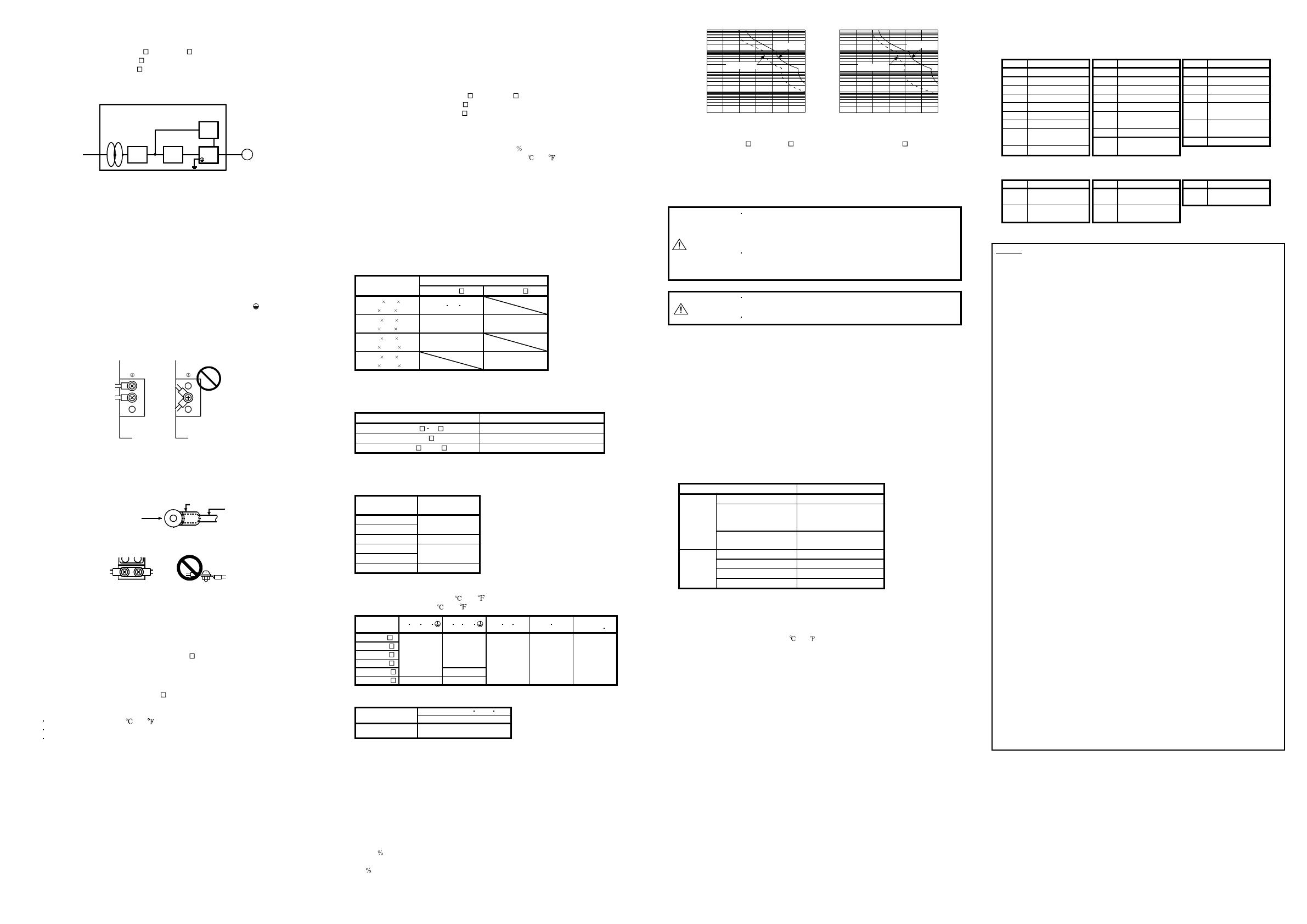
(10)Overload Protection Characteristics
An electronic thermal relay is built in the servo amplifier to protect the servo motor, servo
amplifier and servo motor power line from overloads. The operation characteristics of the
electronic thermal relay are shown below. It is recommended to use an unbalanced
torque-generated machine, such as a vertical motion shaft, so that unbalanced torque is not more
than 70 of the rated torque.
Servo amplifier MR-E series have servo motor overload protection. (The motor full load current is
115 rated current.)
Operation time [s]
Load ratio [%]
1000
100
10
1
0.1
0 50 150 200 250 300100
1000
100
10
1
0.1
0 50 150 200 250 300100
Operation time [s]
Load ratio [%]
In operation
In servo lock
In operation
In servo lock
MR-E-10 to MR-E-100 MR-E-200
(11)Over-temperature protection for motor
Motor Over temperature sensing is not provided by the drive.
4. INSPECTION
WARNING
Before starting maintenance and/or inspection, turn off the power and wait
for 15 minutes or more until the charge lamp turns off. Otherwise, an
electric shock may occur. In addition, always confirm from the front of the
servo amplifier whether the charge lamp is off or not.
Any person who is involved in inspection should be fully competent to do
the work. Otherwise, you may get an electric shock. For repair and parts
replacement, contact your safes representative.
CAUTION
Do not perform insulation resistance test on the servo amplifier as
damage may result.
Do not disassemble and/or repair the equipment on customer side.
(1) Inspection
It is recommended to make the following checks periodically.
(a) Check for loose terminal block screws. Retighten any loose screws.
(b) Check the servo motor bearings, brake section, etc. for unusual noise.
(c) Check the cables and the like for scratches and cracks. Perform periodic inspection according to
operating conditions.
(d) Check the servo motor shaft and coupling for misalignment.
(2) Life
The following parts must be changed periodically as listed below. If any part is found faulty, it
must be changed immediately even when it has not yet reached the end of its life, which depends
on the operating method and environmental conditions.
For use in the atmosphere having much oil mist, dust, etc., clean and inspect every three months.
For parts replacement, please contact your sales representative.
Part name Standard life
Smoothing capacitor 10 years
Relay
Number of power-on and
number of emergency stop
times: 100,000 times
Servo
amplifier
Cooling fan
10,000 to 30,000
hours (2 to 3 years)
Bearings 20,000 to 30,000 hours
Encoder 20,000 to 30,000 hours
Oil seal, V ring 5,000 hours
Servo
motor
Cooling fan 20,000 hours
(a) Smoothing capacitor
Affected by ripple currents, etc. and deteriorates in characteristic. The life of the capacitor
greatly depends on ambient temperature and operating conditions. The capacitor will reach
the end of its life in 10 years of continuous operation in normal air-conditioned environment
(surrounding air temperature of 40 (104 ) or less).
(b) Relays
Their contacts will wear due to switching currents and contact faults occur. Relays reach the
end of their life when the cumulative number of power-on and emergency stop times is 100,000,
which depends on the power supply capacity
(c) Servo amplifier cooling fan
The cooling fan bearings reach the end of their life in 10,000 to 30,000 hours. Normally,
therefore, the fan must be changed in a few years of continuous operation as a guideline.
It must also be changed if unusual noise or vibration is found during inspection.
(d) Servo motor bearings
When the servo motor is run at rated speed under rated load, change the bearings in 20,000 to
30,000 hours as a guideline. This differs on the operating conditions. The bearings must also
be changed if unusual noise or vibration is found during inspection.
(e) Servo motor oil seal, V ring
Must be changed in 5,000 hours of operation at rated speed as a guideline. This differs on the
operating conditions. These parts must also be changed if oil leakage, etc. is found during
inspection.
5. ALARMS AND WARNINGS
5.1 Alarms
Indication Name Indication Name Indication Name
10 Under voltage 24 Main circuit error 46 Servo motor overheat
12 Memory error 1 30 Regenerative error 50 Over load 1
13 Clock error 31 Over speed 51 Over load 2
15 Memory error 2 32 Over current 52 Error excessive
16 Encoder error 1 33 Over voltage Serial communication
17 Board error Command pulse
8A
time-out
19 Memory error 3
35
frequency error Serial communication
Motor combination 37 Parameter error
8E
error
1A
error Main circuit device 88888 Watchdog
20 Encoder error 2
45
overheat
5.2 Warnings
Indication Name Indication Name Indication Name
96
Home position setting
warning
E1 Over load warning E9
Main circuit off
warning
E0
Excessive regenerative
warning
E6
Servo emergency stop
warning
Warranty
1. Warranty period and coverage
We will repair any failure or defect hereinafter referred to as "failure" in our FA equipment hereinafter referred to as the
"Product" arisen during warranty period at no charge due to causes for which we are responsible through the distributor from
which you purchased the Product or our service provider. However, we will charge the actual cost of dispatching our engineer
for an on-site repair work on request by customer in Japan or overseas countries. We are not responsible for any on-site
readjustment and/or trial run that may be required after a defective unit are repaired or replaced.
[Term]
The term of warranty for Product is twelve (12) months after your purchase or delivery of the Product to a place designated by
you or eighteen (18) months from the date of manufacture whichever comes first (“Warranty Period”). Warranty period for
repaired Product cannot exceed beyond the original warranty period before any repair work.
[Limitations]
(1) You are requested to conduct an initial failure diagnosis by yourself, as a general rule. It can also be carried out by us or our
service company upon your request and the actual cost will be charged.
However, it will not be charged if we are responsible for the cause of the failure.
(2) This limited warranty applies only when the condition, method, environment, etc. of use are in compliance with the terms
and conditions and instructions that are set forth in the instruction manual and user manual for the Product and the caution
label affixed to the Product.
(3) Even during the term of warranty, the repair cost will be charged on you in the following cases;
(i) : a failure caused by your improper storing or handling, carelessness or negligence, etc., and a failure caused by your
hardware or software problem
(ii) : a failure caused by any alteration, etc. to the Product made on your side without our approval
(iii) : a failure which may be regarded as avoidable, if your equipment in which the Product is incorporated is equipped with
a safety device required by applicable laws and has any function or structure considered to be indispensable
according to a common sense in the industry
(iv) : a failure which may be regarded as avoidable if consumable parts designated in the instruction manual, etc. are dul
maintained and replaced
(v) : any replacement of consumable parts (battery, fan, smoothing capacitor, etc.)
(vi) : a failure caused by external factors such as inevitable accidents, including without limitation fire and abnormal
fluctuation of voltage, and acts of God, including without limitation earthquake, lightning and natural disasters
(vii) : a failure generated by an unforeseeable cause with a scientific technology that was not available at the time of the
shipment of the Product from our company
(viii) : any other failures which we are not responsible for or which you acknowledge we are not responsible for
2. Term of warranty after the stop of production
(1) We may accept the repair at charge for another seven (7) years after the production of the product is discontinued. The
announcement of the stop of production for each model can be seen in our Sales and Service, etc.
(2) Please note that the Product (including its spare parts) cannot be ordered after its stop of production.
3. Service in overseas countries
Our regional FA Center in overseas countries will accept the repair work of the Product. However, the terms and conditions of
the repair work may differ depending on each FA Center. Please ask your local FA center for details.
4. Exclusion of responsibility for compensation against loss of opportunity, secondary loss, etc.
Whether under or after the term of warranty, we assume no responsibility for any damages arisen from causes for which we
are not responsible, any losses of opportunity and/or profit incurred by you due to a failure of the Product, any damages,
secondary damages or compensation for accidents arisen under a specific circumstance that are foreseen or unforeseen by
our company, any damages to products other than the Product, and also compensation for any replacement work,
readjustment, start-up test run of local machines and the Product and any other operations conducted by you.
5. Change of Product specifications
Specifications listed in our catalogs, manuals or technical documents may be changed without notice.
6. Application and use of the Product
(1) For the use of our General-Purpose AC Servo, its applications should be those that may not result in a serious damage
even if any failure or malfunction occurs in General-Purpose AC Servo, and a backup or fail-safe function should operate
on an external system to General-Purpose AC Servo when any failure or malfunction occurs.
(2) Our General-Purpose AC Servo is designed and manufactured as a general purpose product for use at general industries.
Therefore, applications substantially influential on the public interest for such as atomic power plants and other power
plants of electric power companies, and also which require a special quality assurance system, including applications for
railway companies and government or public offices are not recommended, and we assume no responsibility for any
failure caused by these applications when used.
In addition, applications which may be substantially influential to human lives or properties for such as airlines, medical
treatments, railway service, incineration and fuel systems, man-operated material handling equipment, entertainment
machines, safety machines, etc. are not recommended, and we assume no responsibility for any failure caused by these
applications when used.
We will review the acceptability of the abovementioned applications, if you agree not to require a specific quality for a
specific application. Please contact us for consultation.


