

A - 1
SAFETY PRECAUTIONS
(Please read these instructions before using this equipment.)
Before using this product, please read this manual and the relevant manuals introduced in this manual
carefully and pay full attention to safety to handle the product correctly.
These precautions apply only to this product.
In this manual, the safety instructions are ranked as "DANGER" and "CAUTION".
DANGER
Indicates that incorrect handling may cause hazardous
conditions, resulting in death or severe injury.
CAUTION
Indicates that incorrect handling may cause hazardous
conditions, resulting in medium or slight personal injury or
physical damage.
Depending on circumstances, procedures indicated by
CAUTION may also be linked to serious
results.
In any case, it is important to follow the directions for usage.
Please save this manual to make it accessible when required and always forward it to the end user.

A - 2
For Safe Operations
1. Prevention of electric shocks
DANGER
Never open the front case or terminal covers of the servo amplifier while the power is ON or the
unit is running, as this may lead to electric shocks.
Never run the unit with the front case or terminal cover of the servo amplifier removed. The high
voltage terminal and charged sections will be exposed and may lead to electric shocks.
Never open the front case or terminal cover of the servo amplifier at times other than wiring work
or periodic inspections even if the power is OFF. The insides of the position board and servo
amplifier are charged and may lead to electric shocks.
Completely turn off the externally supplied power used in the system before mounting or
removing the position board, performing wiring work, or inspections. Failing to do so may lead to
electric shocks.
When performing wiring work or inspections, turn the power OFF, wait at least ten minutes, and
then check the voltage with a tester, etc. Failing to do so may lead to electric shocks.
Be sure to ground the controller incorporating the position board, servo amplifier and servo
motor. (Ground resistance : 100
or less) Do not ground commonly with other devices.
The wiring work and inspections must be done by a qualified technician.
Wire the units after installing the position board, servo amplifier and servo motor. Failing to do so
may lead to electric shocks or damage.
Never operate the switches with wet hands, as this may lead to electric shocks.
Do not damage, apply excessive stress, place heavy things on or sandwich the cables, as this
may lead to electric shocks.
Do not touch the position board, servo amplifier or servo motor terminal blocks while the power is
ON, as this may lead to electric shocks.
Do not touch the built-in power supply, built-in grounding or signal wires of the position board
and servo amplifier, as this may lead to electric shocks.
2. For fire prevention
CAUTION
Install the position board, servo amplifier, servo motor and regenerative resistor on incombustible.
Installing them directly or close to combustibles will lead to fire.
If a fault occurs in the position board or servo amplifier, shut the power OFF at the servo
amplifier’s power source. If a large current continues to flow, fire may occur.
When using a regenerative resistor, shut the power OFF with an error signal. The regenerative
resistor may abnormally overheat due to a fault in the regenerative transistor, etc., and may lead
to fire.
Always take heat measures such as flame proofing for the inside of the control panel where the
servo amplifier or regenerative resistor is installed and for the wires used. Failing to do so may
lead to fire.
Do not damage, apply excessive stress, place heavy things on or sandwich the cables, as this
may lead to fire.

A - 3
3. For injury prevention
CAUTION
Do not apply a voltage other than that specified in this manual and the instruction manual of the
product you are using on any terminal.
Doing so may lead to destruction or damage.
Do not mistake the terminal connections, as this may lead to destruction or damage.
Do not mistake the polarity ( + / - ), as this may lead to destruction or damage.
Do not touch the heat radiating fins of position board or servo amplifier, regenerative resistor and
servo motor, etc., while the power is ON and for a short time after the power is turned OFF. In this
timing, these parts become very hot and may lead to burns.
Always turn the power OFF before touching the servo motor shaft or coupled machines, as these
parts may lead to injuries.
Do not go near the machine during test operations or during operations such as teaching.
Doing so may lead to injuries.
4. Various precautions
Strictly observe the following precautions.
Mistaken handling of the unit may lead to faults, injuries or electric shocks.
(1) System structure
CAUTION
Always install a leakage breaker on the controller incorporating the position board and servo
amplifier power source.
If installation of an electromagnetic contactor for power shut off during an error, etc., is specified in
the instruction manual for the servo amplifier, etc., always install the electromagnetic contactor.
Install the emergency stop circuit externally so that the operation can be stopped immediately and
the power shut off.
Use the position board, servo amplifier, servo motor and regenerative resistor with the correct
combinations listed in the instruction manual. Other combinations may lead to fire or faults.
If safety standards (ex., robot safety rules, etc.,) apply to the system using the position board,
servo amplifier and servo motor, make sure that the safety standards are satisfied.
Construct a safety circuit externally of the position board or servo amplifier if the abnormal
operation of the position board or servo amplifier differ from the safety directive operation in the
system.
In systems where coasting of the servo motor will be a problem during the forced stop, emergency
stop, servo OFF or power supply OFF, use dynamic brakes.
Make sure that the system considers the coasting amount even when using dynamic brakes.
In systems where perpendicular shaft dropping may be a problem during the forced stop,
emergency stop, servo OFF or power supply OFF, use both dynamic brakes and electromagnetic
brakes.

A - 4
CAUTION
The dynamic brakes must be used only on errors that cause the forced stop, emergency stop, or
servo OFF. These brakes must not be used for normal braking.
The brakes (electromagnetic brakes) assembled into the servo motor are for holding applications,
and must not be used for normal braking.
The system must have a mechanical allowance so that the machine itself can stop even if the
stroke limits switch is passed through at the max. speed.
Use wires and cables that have a wire diameter, heat resistance and bending resistance
compatible with the system.
Use wires and cables within the length of the range described in the instruction manual.
The ratings and characteristics of the parts (other than position board, servo amplifier and servo
motor) used in a system must be compatible with the position board, servo amplifier and servo
motor.
Install a cover on the shaft so that the rotary parts of the servo motor are not touched during
operation.
There may be some cases where holding by the electromagnetic brakes is not possible due to the
life or mechanical structure (when the ball screw and servomotor are connected with a timing belt,
etc.). Install a stopping device to ensure safety on the machine side.
(2) Parameter settings and programming
CAUTION
Set the parameter values to those that are compatible with the position board, servo amplifier,
servo motor and regenerative resistor model and the system application. The protective functions
may not function if the settings are incorrect.
The regenerative resistor model and capacity parameters must be set to values that conform to
the operation mode and servo amplifier. The protective functions may not function if the settings
are incorrect.
Set the mechanical brake output and dynamic brake output validity parameters to values that are
compatible with the system application. The protective functions may not function if the settings
are incorrect.
Set the stroke limit input validity parameter to a value that is compatible with the system
application. The protective functions may not function if the setting is incorrect.
Set the servo motor encoder type (increment, absolute position type, etc.) parameter to a value
that is compatible with the system application. The protective functions may not function if the
setting is incorrect.
Set the servo motor capacity and type (standard, low-inertia, flat, etc.) parameter to values that
are compatible with the system application. The protective functions may not function if the
settings are incorrect.
Set the servo amplifier capacity and type parameters to values that are compatible with the
system application. The protective functions may not function if the settings are incorrect.
Use the program commands for the program with the conditions specified in the instruction
manual.

A - 5
(3) Transportation and installation
CAUTION
Transport the product with the correct method according to the mass.
Use the servo motor suspension bolts only for the transportation of the servo motor. Do not
transport the servo motor with machine installed on it.
Do not stack products past the limit.
When transporting, installing, and removing the position board, never touch the print board
inner part and electronic components. Hold the front panel or edge of the print board.
When transporting the position board or servo amplifier, never hold the connected wires or
cables.
When transporting the servo motor, never hold the cables, shaft or detector.
When transporting the position board or servo amplifier, never hold the front case as it may fall
off.
When transporting, installing or removing the position board or servo amplifier, never hold the
edges.
Install the unit according to the instruction manual in a place where the mass can be withstood.
Do not get on or place heavy objects on the product.
Always observe the installation direction.
Mount the position board to a connector or slot that is compatible with standards, and keep the
designated clearance between the position board and other boards.
Keep the designated clearance between the position board or servo amplifier and control panel
inner surface or the position board and servo amplifier, position board or servo amplifier and
other devices.
Do not install or operate position board, servo amplifiers or servo motors that are damaged or
that have missing parts.
Do not block the intake/outtake ports of the servo amplifier and servo motor with cooling fan.
Do not allow conductive matter such as screw or cutting chips or combustible matter such as oil
enter the position board, servo amplifier or servo motor.
The position board, servo amplifier and servo motor are precision machines, so do not drop or
apply strong impacts on them.
Securely fix the position board, servo amplifier and servo motor to the machine according to the
instruction manual. If the fixing is insufficient, these may come off during operation.

A - 6
CAUTION
Always install the servo motor with reduction gears in the designated direction. Failing to do so
may lead to oil leaks.
Store and use the unit in the following environmental conditions.
Environment
Conditions
Position board/Servo amplifier Servomotor
Ambient
temperature
According to each instruction manual.
0°C to +40°C (With no freezing)
(32°F to +104°F)
Ambient humidity According to each instruction manual.
80% RH or less
(With no dew condensation)
Storage
temperature
According to each instruction manual.
-20°C to +65°C
(-4°F to +149°F)
Atmosphere
Indoors (where not subject to direct sunlight).
No corrosive gases, flammable gases, oil mist or dust must exist
Altitude 1000m (3280.84ft.) or less above sea level
Vibration According to each instruction manual
When coupling with the synchronous encoder or servo motor shaft end, do not apply impact such
as by hitting with a hammer. Doing so may lead to detector damage.
Do not apply a load larger than the tolerable load onto the synchronous encoder and servo motor
shaft. Doing so may lead to shaft breakage.
When not using for a long time, disconnect the power line from the servo amplifier.
Place the position board and servo amplifier in static electricity preventing vinyl bags and store.
When storing for a long time, please contact with our sales representative.
Also, execute a trial operation.
When fumigants that contain halogen materials such as fluorine, chlorine, bromine, and iodine
are used for disinfecting and protecting wooden packaging from insects, they cause malfunction
when entering our products.
Please take necessary precautions to ensure that remaining materials from fumigant do not
enter our products, or treat packaging with methods other than fumigation (heat method).
Additionally, disinfect and protect wood from insects before packing products.

A - 7
(4) Wiring
CAUTION
Correctly and securely wire the wires. Reconfirm the connections for mistakes and the terminal
screws for tightness after wiring. Failing to do so may lead to run away of the servo motor.
After wiring, install the protective covers such as the terminal covers to the original positions.
Do not install a phase advancing capacitor, surge absorber or radio noise filter (option FR-BIF)
on the output side of the servo amplifier.
Correctly connect the output side (terminal U, V, W) and ground. Incorrect connections will lead
the servo motor to operate abnormally.
Do not connect a commercial power supply to the servo motor, as this may lead to trouble.
Do not mistake the direction of the surge absorbing diode installed on the DC relay for the control
signal output of brake signals, etc. Incorrect installation may lead to signals not being output
when trouble occurs or the protective functions not functioning.
DICOM
RA
Control output
signal
DOCOM
Servo amplifier
24VDC
Control output
signal
DICOM
DOCOM
Servo amplifier
RA
24VDC
For the sink output interface For the source output interface
Do not connect or disconnect the connection cables between each unit or the encoder cable
while the power is ON.
Securely tighten the cable connector fixing screws and fixing mechanisms. Insufficient fixing may
lead to the cables coming off during operation.
Do not bundle the power line or cables.
(5) Trial operation and adjustment
CAUTION
Confirm and adjust the program and each parameter before operation. Unpredictable
movements may occur depending on the machine.
Extreme adjustments and changes may lead to unstable operation, so never make them.
When using the absolute position system function, on starting up, and when the position board
or absolute value motor has been replaced, always perform a home position return.
Before starting test operation, set the parameter speed limit value to the slowest value, and
make sure that operation can be stopped immediately by the forced stop, etc. if a hazardous
state occurs.

A - 8
(6) Usage methods
CAUTION
Immediately turn OFF the power if smoke, abnormal sounds or odors are emitted from the
position board, servo amplifier or servo motor.
Always execute a test operation before starting actual operations after the program or
parameters have been changed or after maintenance and inspection.
Do not attempt to disassemble and repair the units excluding a qualified technician whom our
company recognized.
Do not make any modifications to the unit.
Keep the effect or electromagnetic obstacles to a minimum by installing a noise filter or by using
wire shields, etc. Electromagnetic obstacles may affect the electronic devices used near the
position board or servo amplifier.
When using the CE Mark-compliant equipment, refer to this manual for the position boards and
refer to the corresponding EMC guideline information for the servo amplifiers, inverters and other
equipment.
Use the units with the following conditions.
Item Conditions
Input power According to each instruction manual.
Input frequency According to each instruction manual.
Tolerable momentary power failure According to each instruction manual.
(7) Corrective actions for errors
CAUTION
If an error occurs in the self diagnosis of the position board or servo amplifier, confirm the check
details according to the instruction manual, and restore the operation.
If a dangerous state is predicted in case of a power failure or product failure, use a servo motor
with electromagnetic brakes or install a brake mechanism externally.
Use a double circuit construction so that the electromagnetic brake operation circuit can be
operated by emergency stop signals set externally.
24VDC
B
RA1
EMG
Servo motor
Electromagnetic
brakes
Shut off with the
emergency stop
signal (EMG).
Shut off with servo ON signal OFF,
alarm, electromagnetic brake signal.
If an error occurs, remove the cause, secure the safety and then resume operation after alarm
release.
The unit may suddenly resume operation after a power failure is restored, so do not go near the
machine. (Design the machine so that personal safety can be ensured even if the machine
restarts suddenly.)

A - 9
(8) Maintenance, inspection and part replacement
CAUTION
Perform the daily and periodic inspections according to the instruction manual.
Perform maintenance and inspection after backing up the program and parameters for the
position board and servo amplifier.
Do not place fingers or hands in the clearance when opening or closing any opening.
Periodically replace consumable parts such as batteries according to the instruction manual.
Do not touch the lead sections such as ICs or the connector contacts.
Before touching the position board, always touch grounded metal, etc. to discharge static
electricity from human body. Failure to do so may cause the position board to fail or malfunction.
Do not directly touch the position board's conductive parts and electronic components.
Touching them could cause an operation failure or give damage to the position board.
Do not place the position board or servo amplifier on metal that may cause a power leakage or
wood, plastic or vinyl that may cause static electricity buildup.
Do not perform a megger test (insulation resistance measurement) during inspection.
When replacing the position board or servo amplifier, always set the new position board
settings correctly.
When the position board or absolute value motor has been replaced, carry out a home position
return operation from the user program. Failing to do so may cause position displacement.
After maintenance and inspections are completed, confirm that the position detection of the
absolute position detector function is correct.
Do not drop or impact the battery installed to the module.
Doing so may damage the battery, causing battery liquid to leak in the battery. Do not use the
dropped or impacted battery, but dispose of it.
Do not short circuit, charge, overheat, incinerate or disassemble the batteries.
The electrolytic capacitor will generate gas during a fault, so do not place your face near the
position board or servo amplifier.
The electrolytic capacitor and fan will deteriorate. Periodically replace these to prevent secondary
damage from faults. Replacements can be made by our sales representative.
Lock the control panel and prevent access to those who are not certified to handle or install
electric equipment.
Do not burn or break a position board and servo amplifier. Doing so may cause a toxic gas.

A - 10
(9) About processing of waste
When you discard position board, servo amplifier, a battery (primary battery) and other option articles,
please follow the law of each country (area).
CAUTION
This product is not designed or manufactured to be used in equipment or systems in situations
that can affect or endanger human life.
When considering this product for operation in special applications such as machinery or systems
used in passenger transportation, medical, aerospace, atomic power, electric power, or
submarine repeating applications, please contact your nearest Mitsubishi sales representative.
Although this product was manufactured under conditions of strict quality control, you are strongly
advised to install safety devices to forestall serious accidents when it is used in facilities where a
breakdown in the product is likely to cause a serious accident.
(10) General cautions
All drawings provided in the instruction manual show the state with the covers and safety
partitions removed to explain detailed sections. When operating the product, always return the
covers and partitions to the designated positions, and operate according to the instruction
manual.

A - 11
REVISIONS
The manual number is given on the bottom left of the back cover.
Print Date Manual Number Revision
Dec., 2013 IB(NA)-0300223-A First edition
Dec., 2014 IB(NA)-0300223-B [Additional model]
MR-MC240, MR-MC241
[Additional function]
Speed-torque control, Mark detection, Continuous operation to torque
control, External forced stop disabled
[Additional correction]
Alarm history, Home position return change while system is running,
High speed monitor position droop, Table map, Log data (event code
list, information for each event), Parameters (servo parameters,
control parameters), Monitor number (operation information), Alarm
number (system alarm, operation alarm), Supplementary explanation
for the use of linear servo system, Supplementary explanation for the
use of SSCNET
compatible servo amplifier, Connector exterior
dimensions
Japanese Manual Number IB(NA)-0300222
This manual confers no industrial property rights or any rights of any other kind, nor does it confer any patent
licenses. Mitsubishi Electric Corporation cannot be held responsible for any problems involving industrial property
rights which may occur as a result of using the contents noted in this manual.
© 2013 MITSUBISHI ELECTRIC CORPORATION

A - 12
INTRODUCTION
Thank you for choosing the Mitsubishi position board MR-MC210/MR-MC211/MR-MC240/MR-MC241.
Before using the equipment, please read this manual carefully to develop full familiarity with the functions
and performance of the position board you have purchased, so as to ensure correct use.
CONTENTS
Safety Precautions ......................................................................................................................................... A- 1
Revisions ........................................................................................................................................................A-11
Contents .........................................................................................................................................................A-12
About Manuals ................................................................................................................................................A-21
1. SUMMARY 1- 1 to 1-24
1.1 Summary ................................................................................................................................................... 1- 1
1.2 Features..................................................................................................................................................... 1- 6
1.3 Specifications ............................................................................................................................................ 1- 9
1.3.1 General specifications ........................................................................................................................ 1- 9
1.3.2 List of specifications of position board .............................................................................................. 1-10
1.4 Name of each section .............................................................................................................................. 1-13
1.4.1 Name of parts for PCI bus compatible position board ..................................................................... 1-13
1.4.2 Name of parts for PCI Express
®
bus compatible position board ..................................................... 1-15
1.5 Bus interface ............................................................................................................................................. 1-17
1.5.1 Configuration register ........................................................................................................................ 1-17
1.5.2 Dual port memory map...................................................................................................................... 1-19
1.5.3 Module information ............................................................................................................................ 1-20
1.6 SSCNET
cables .................................................................................................................................... 1-22
1.7 Forced stop input terminal ....................................................................................................................... 1-23
2. SYSTEM CONFIGURATION 2- 1 to 2- 8
2.1 Position board configuration ..................................................................................................................... 2- 1
2.1.1 MR-MC210 system configuration ...................................................................................................... 2- 1
2.1.2 MR-MC211 system configuration ...................................................................................................... 2- 2
2.1.3 MR-MC240 system configuration ...................................................................................................... 2- 3
2.1.4 MR-MC241 system configuration ...................................................................................................... 2- 4
2.2 System configuration equipment .............................................................................................................. 2- 5
2.3 Checking serial number and operating system software version ............................................................ 2- 6
2.3.1 Checking serial number ..................................................................................................................... 2- 6
2.3.2 Checking software version ................................................................................................................. 2- 6
2.4 Restrictions by the Software's Version ..................................................................................................... 2- 7
3. INSTALLATION AND WIRING 3- 1 to 3- 6
3.1 Board installation ....................................................................................................................................... 3- 1
3.1.1 Instructions for handling ..................................................................................................................... 3- 1
3.1.2 Installation environment ..................................................................................................................... 3- 1
3.2 Connection and disconnection of cable.................................................................................................... 3- 2
3.2.1 SSCNET
cable ................................................................................................................................ 3- 2

A - 13
3.2.2 Forced stop input cable ...................................................................................................................... 3- 6
4. SYSTEM STARTUP 4- 1 to 4-18
4.1 Startup procedures .................................................................................................................................... 4- 1
4.2 Check of wiring and ambient environment ............................................................................................... 4- 2
4.3 Position board setting ................................................................................................................................ 4- 3
4.4 Servo amplifier setting ............................................................................................................................... 4- 4
4.5 Parameter setting ...................................................................................................................................... 4- 6
4.5.1 Parameter initialization ....................................................................................................................... 4- 6
4.5.2 System option 1 setting ...................................................................................................................... 4- 7
4.5.3 System option 2 setting ...................................................................................................................... 4- 9
4.5.4 Control option 1 setting ..................................................................................................................... 4-10
4.5.5 Axis No. assignment.......................................................................................................................... 4-11
4.5.6 Sensor input option setting................................................................................................................ 4-13
4.5.7 Vendor ID and type code setting ...................................................................................................... 4-16
4.6 System startup processing ...................................................................................................................... 4-17
5. OPERATIONAL FUNCTIONS 5- 1 to 5-42
5.1 JOG operation ........................................................................................................................................... 5- 2
5.1.1 Summary ............................................................................................................................................ 5- 2
5.1.2 Start operation method ....................................................................................................................... 5- 2
5.1.3 Resuming operation ........................................................................................................................... 5- 3
5.2 Incremental feed ........................................................................................................................................ 5- 4
5.2.1 Summary ............................................................................................................................................ 5- 4
5.2.2 Start operation method ....................................................................................................................... 5- 5
5.3 Automatic operation .................................................................................................................................. 5- 6
5.3.1 Summary ............................................................................................................................................ 5- 6
5.3.2 Start operation method ....................................................................................................................... 5- 7
5.3.3 Auxiliary command ............................................................................................................................. 5- 8
5.3.4 Other axes start specification ............................................................................................................ 5-15
5.3.5 S-curve ratio ...................................................................................................................................... 5-15
5.4 Linear interpolation ................................................................................................................................... 5-16
5.4.1 Summary ........................................................................................................................................... 5-16
5.4.2 Settings .............................................................................................................................................. 5-18
5.4.3 Start operation method ...................................................................................................................... 5-19
5.4.4 Processing for exceeding speed limit for each axis ......................................................................... 5-20
5.4.5 Restrictions ........................................................................................................................................ 5-21
5.5 Home position return ................................................................................................................................ 5-22
5.5.1 Summary ........................................................................................................................................... 5-22
5.5.2 Home position return method ........................................................................................................... 5-24
5.5.3 Start operation method ...................................................................................................................... 5-25
5.5.4 Home position return using a dog method ....................................................................................... 5-27
5.5.5 Home position return using a data set method ................................................................................ 5-29
5.5.6 Home position return using a stopper method ................................................................................. 5-29
5.5.7 Home position return using a dog cradle method ............................................................................ 5-30
5.5.8 Home position return using a limit switch combined method........................................................... 5-32
5.5.9 Home position return using a limit switch front end method ............................................................ 5-32
5.5.10 Home position return using a dog front end method ...................................................................... 5-33

A - 14
5.5.11 Home position return using a Z-phase detection method .............................................................. 5-35
5.5.12 Home position return using a scale home position signal detection method ................................ 5-38
5.5.13 Home position return using a scale home position signal detection method 2 ............................. 5-39
5.6 Home position reset function (data set function) ..................................................................................... 5-40
6. APPLICATION FUNCTIONS 6- 1 to 6-146
6.1 Command units ......................................................................................................................................... 6- 1
6.1.1 Position command unit - electronic gear ........................................................................................... 6- 1
6.1.2 Settings ............................................................................................................................................... 6- 3
6.1.3 Setting example of electronic gears .................................................................................................. 6- 3
6.1.4 Restrictions ......................................................................................................................................... 6- 4
6.2 Speed unit ................................................................................................................................................. 6- 5
6.2.1 Settings ............................................................................................................................................... 6- 5
6.2.2 Setting example of speed units .......................................................................................................... 6- 6
6.2.3 Speed limit .......................................................................................................................................... 6- 6
6.3 Acceleration/deceleration .......................................................................................................................... 6- 7
6.3.1 Linear acceleration/deceleration ........................................................................................................ 6- 7
6.3.2 Smoothing filter ................................................................................................................................... 6- 8
6.3.3 Start up speed validity ........................................................................................................................ 6- 8
6.3.4 S-curve acceleration/deceleration (Sine acceleration/deceleration) ................................................ 6- 9
6.4 Servo off ................................................................................................................................................... 6-13
6.5 Forced stop ............................................................................................................................................... 6-14
6.6 Stop operation .......................................................................................................................................... 6-15
6.7 Rapid stop operation ................................................................................................................................ 6-16
6.8 Limit switch (stroke end) .......................................................................................................................... 6-17
6.9 Software limit ............................................................................................................................................ 6-18
6.10 Interlock .................................................................................................................................................. 6-20
6.11 Rough match output ............................................................................................................................... 6-22
6.12 Torque limit ............................................................................................................................................. 6-23
6.13 Command change .................................................................................................................................. 6-24
6.13.1 Speed change ................................................................................................................................. 6-24
6.13.2 Change of time constants ............................................................................................................... 6-25
6.13.3 Position change ............................................................................................................................... 6-26
6.14 Backlash ................................................................................................................................................. 6-32
6.15 Position switch ........................................................................................................................................ 6-33
6.16 Completion of operation signal .............................................................................................................. 6-34
6.17 Interference check function .................................................................................................................... 6-40
6.17.1 Interface ........................................................................................................................................... 6-42
6.17.2 Interference check operation image diagram ................................................................................. 6-43
6.17.3 Checks prior to start up ................................................................................................................... 6-44
6.17.4 Operation check .............................................................................................................................. 6-45
6.18 Home position search limit ..................................................................................................................... 6-48
6.18.1 Summary ......................................................................................................................................... 6-48
6.18.2 Set items .......................................................................................................................................... 6-48
6.18.3 Home position search limit operation example .............................................................................. 6-49
6.19 Gain changing ........................................................................................................................................ 6-50
6.20 PI-PID switching ..................................................................................................................................... 6-52
6.21 Absolute position detection system ....................................................................................................... 6-53
6.21.1 Parameters ...................................................................................................................................... 6-53

A - 15
6.21.2 Processing procedure ..................................................................................................................... 6-54
6.21.3 Sequence example ......................................................................................................................... 6-56
6.22 Home position return request ................................................................................................................ 6-58
6.23 Other axes start ...................................................................................................................................... 6-60
6.23.1 Summary ......................................................................................................................................... 6-60
6.23.2 Settings ............................................................................................................................................ 6-60
6.23.3 Interface ........................................................................................................................................... 6-66
6.23.4 Operation example .......................................................................................................................... 6-69
6.24 High response I/F ................................................................................................................................... 6-73
6.24.1 Summary ......................................................................................................................................... 6-73
6.24.2 Interface ........................................................................................................................................... 6-74
6.24.3 Fast start operation ......................................................................................................................... 6-75
6.24.4 Interrupt processing high speed completion .................................................................................. 6-76
6.25 In-position signal .................................................................................................................................... 6-77
6.26 Digital input/output ................................................................................................................................. 6-78
6.26.1 Summary ......................................................................................................................................... 6-78
6.26.2 Interface ........................................................................................................................................... 6-79
6.27 Servo amplifier general input/output ...................................................................................................... 6-80
6.27.1 Summary ......................................................................................................................................... 6-80
6.27.2 Settings ............................................................................................................................................ 6-82
6.28 Dual port memory exclusive control ...................................................................................................... 6-85
6.28.1 Summary ......................................................................................................................................... 6-85
6.28.2 Exclusive control of digital output ................................................................................................... 6-85
6.29 Pass position interrupt............................................................................................................................ 6-87
6.29.1 Summary ......................................................................................................................................... 6-87
6.29.2 Pass position interrupt setting method ........................................................................................... 6-88
6.29.3 Interface ........................................................................................................................................... 6-89
6.29.4 Operation example ........................................................................................................................ 6-100
6.30 Mark detection ...................................................................................................................................... 6-104
6.30.1 Summary ....................................................................................................................................... 6-104
6.30.2 Interface ......................................................................................................................................... 6-108
6.30.3 Function details ............................................................................................................................. 6-116
6.30.4 Operation example ........................................................................................................................ 6-118
6.31 Continuous operation to torque control ............................................................................................... 6-121
6.31.1 Summary ....................................................................................................................................... 6-121
6.31.2 Interface ......................................................................................................................................... 6-123
6.31.3 Control mode switch ...................................................................................................................... 6-134
6.31.4 Operation timing ............................................................................................................................ 6-136
6.31.5 Operation during continuous operation to torque control mode .................................................. 6-140
6.31.6 Stop factors during continuous operation to torque control ......................................................... 6-141
6.31.7 Combinations of continuous operation to torque control and other functions ............................. 6-143
6.31.8 Restrictions on servo amplifier functions ..............................................................................
........ 6-145
7.
AU
XILIARY FUNCTION 7- 1 to 7-108
7.1 Reading/writing parameters ...................................................................................................................... 7- 1
7.1.1 Writing parameters ............................................................................................................................. 7- 1
7.1.2 Reading parameters ........................................................................................................................... 7- 3
7.2 Changing parameters at the servo ........................................................................................................... 7- 4
7.3 Alarm and system error ............................................................................................................................. 7- 6

A - 16
7.4 Monitor function ......................................................................................................................................... 7- 8
7.4.1 Summary ............................................................................................................................................ 7- 8
7.4.2 Monitor latch function ........................................................................................................................ 7-10
7.5 High speed monitor function .................................................................................................................... 7-11
7.5.1 Summary ........................................................................................................................................... 7-11
7.5.2 Monitor latch function ........................................................................................................................ 7-12
7.6 Interrupt .................................................................................................................................................... 7-13
7.6.1 Interrupt sequence ............................................................................................................................ 7-13
7.6.2 Interrupt conditions ............................................................................................................................ 7-15
7.6.3 Factor of interrupt .............................................................................................................................. 7-16
7.6.4 Interrupt processing example............................................................................................................ 7-24
7.7 User watchdog function ........................................................................................................................... 7-25
7.8 Software reboot function .......................................................................................................................... 7-26
7.9 Parameter backup .................................................................................................................................... 7-27
7.10 Test mode ............................................................................................................................................... 7-31
7.10.1 Structural diagram ........................................................................................................................... 7-31
7.10.2 Test operation mode ....................................................................................................................... 7-32
7.11 Reconnect/disconnect function .............................................................................................................. 7-33
7.11.1 Disconnection function summary .................................................................................................... 7-33
7.11.2 Reconnect function summary ......................................................................................................... 7-34
7.11.3 Interface ........................................................................................................................................... 7-35
7.11.4 Disconnection method..................................................................................................................... 7-36
7.11.5 Reconnection method ..................................................................................................................... 7-37
7.11.6 Restrictions ...................................................................................................................................... 7-38
7.12 Sampling ................................................................................................................................................. 7-39
7.12.1 Summary ......................................................................................................................................... 7-39
7.12.2 Command/status bit ........................................................................................................................ 7-40
7.12.3 Command/status data ..................................................................................................................... 7-43
7.12.4 Sampling setting write/read ............................................................................................................. 7-46
7.12.5 Details for sampling function settings ............................................................................................. 7-47
7.12.6 Number of sampled points .............................................................................................................. 7-53
7.12.7 Sampling items ................................................................................................................................ 7-54
7.12.8 Sampling trigger .............................................................................................................................. 7-60
7.12.9 Sampling data read ......................................................................................................................... 7-63
7.12.10 Timing chart for sampling function ................................................................................................ 7-65
7.13 Log .......................................................................................................................................................... 7-74
7.13.1 Summary ......................................................................................................................................... 7-74
7.13.2 Log data details ............................................................................................................................... 7-75
7.13.3 Event code list ................................................................................................................................. 7-76
7.13.4 Information for each event .............................................................................................................. 7-78
7.13.5 Log function interface ...................................................................................................................... 7-87
7.13.6 Timing chart for reading of log data ................................................................................................ 7-90
7.13.7 Log acquiring selection ................................................................................................................... 7-90
7.14 Operation cycle monitor function ........................................................................................................... 7-91
7.14.1 Summary ................................................................................................................
......................... 7-91
7.1
4.
2 Interface ........................................................................................................................................... 7-91
7.14.3 Operation timing .............................................................................................................................. 7-92
7.15 External forced stop disabled ................................................................................................................ 7-94
7.15.1 Summary ......................................................................................................................................... 7-94
7.15.2 Interface ........................................................................................................................................... 7-94

A - 17
7.15.3 Setting method ................................................................................................................................ 7-94
7.16 Amplifier-less axis function .................................................................................................................... 7-95
7.16.1 Summary ......................................................................................................................................... 7-95
7.16.2 Interface ........................................................................................................................................... 7-95
7.16.3 Control details .................................................................................................................................. 7-96
7.17 Alarm history function............................................................................................................................. 7-97
7.17.1 Summary ......................................................................................................................................... 7-97
7.17.2 Alarm history data details ................................................................................................................ 7-98
7.17.3 Interface ......................................................................................................................................... 7-103
7.17.4 Timing chart for alarm history read ............................................................................................... 7-106
7.17.5 Alarm history initialization procedure ............................................................................................ 7-107
7.17.6 List of system errors that do not apply to alarm history storage .................................................. 7-107
8. TANDEM DRIVE 8- 1 to 8-32
8.1 Drive modes .............................................................................................................................................. 8- 1
8.1.1 Synchronous mode ............................................................................................................................ 8- 2
8.1.2 Non-synchronous micro-adjustment control mode ........................................................................... 8- 2
8.1.3 Changing of drive mode ..................................................................................................................... 8- 3
8.2 Parameter settings .................................................................................................................................... 8- 4
8.2.1 Designation of tandem drive axes ..................................................................................................... 8- 4
8.2.2 Servo parameters ............................................................................................................................... 8- 4
8.2.3 Control parameters ............................................................................................................................. 8- 4
8.3 Axis data classifications ............................................................................................................................ 8- 5
8.3.1 Only data from master axis is valid .................................................................................................... 8- 5
8.3.2 Individual data for master axis/slave axis .......................................................................................... 8- 5
8.4 Tandem drive axis operation .................................................................................................................... 8- 6
8.4.1 Home position return during tandem drive ........................................................................................ 8- 6
8.4.2 JOG operation during tandem drive ................................................................................................. 8-24
8.4.3 Incremental feed while using tandem drive ...................................................................................... 8-25
8.4.4 Automatic operation during tandem drive ......................................................................................... 8-26
8.4.5 Linear interpolation during tandem drive .......................................................................................... 8-27
8.5 Servo on and servo off during tandem drive axis operation ................................................................... 8-29
8.6 Tandem drive axis limit switch ................................................................................................................. 8-30
8.7 Tandem drive axis software limit ............................................................................................................. 8-31
8.8 Tandem drive interference check ............................................................................................................ 8-31
8.9 Tandem drive axis servo alarms .............................................................................................................. 8-32
8.10 Deviation monitoring function ................................................................................................................ 8-32
9. INTERFACE MODE 9- 1 to 9-40
9.1 Summary ................................................................................................................................................... 9- 1
9.2 Combinations with functions ..................................................................................................................... 9- 2
9.3 Parameters ................................................................................................................................................ 9- 4
9.4 Interface ..................................................................................................................................................... 9- 6
9.5 Control method ......................................................................................................................................... 9-11
9.5.1 Control mode ..................................................................................................................................... 9-11
9.5.2 Position control mode ........................................................................................................................ 9-12
9.5.3 Speed control mode .......................................................................................................................... 9-14
9.5.4 Torque control mode ......................................................................................................................... 9-16

A - 18
9.5.5 Control method for interrupt output invalid ....................................................................................... 9-18
9.5.6 Control method for interrupt output valid .......................................................................................... 9-21
9.5.7 Procedure for switching control mode .............................................................................................. 9-26
9.5.8 Examples of switching control mode ................................................................................................ 9-28
9.6 Interrupt output cycle ................................................................................................................................ 9-31
9.7 Command data update cycle ................................................................................................................... 9-32
9.8 Servo off ................................................................................................................................................... 9-33
9.9 Home position return ................................................................................................................................ 9-34
9.10 Coordinate management ....................................................................................................................... 9-36
9.10.1 Incremental system ......................................................................................................................... 9-36
9.10.2 Absolute position system ................................................................................................................ 9-38
9.11 Precautions............................................................................................................................................. 9-40
10. TABLE MAP 10- 1 to 10-52
10.1 Table list ................................................................................................................................................ 10- 1
10.2 System information ............................................................................................................................... 10- 3
10.3 System command/status table ............................................................................................................. 10- 5
10.4 Factor of interrupt ................................................................................................................................. 10-17
10.5 System configuration information table ............................................................................................... 10-25
10.6 Axis data ............................................................................................................................................... 10-26
10.6.1 Axis data command table .............................................................................................................. 10-26
10.6.2 Axis data status table .................................................................................................................... 10-33
10.7 Servo parameter change number ........................................................................................................ 10-41
10.8 Point number offset .............................................................................................................................. 10-45
10.9 Command buffers ................................................................................................................................. 10-46
10.10 Digital input/output table .................................................................................................................... 10-48
10.11 Mark detection command/status table .............................................................................................. 10-49
10.12 Mark detection data tables ................................................................................................................. 10-50
10.13 Continuous operation to torque control data table ............................................................................ 10-51
11. PARAMETERS 11- 1 to 11-36
11.1 System parameters ............................................................................................................................... 11- 2
11.2 Servo parameters .................................................................................................................................. 11- 4
11.2.1 Servo amplifier MR-J4(W
)- B .................................................................................................... 11- 4
11.3 Control parameters .............................................................................................................................. 11-22
12. MONITOR NUMBER 12- 1 to 12-20
12.1 Servo information (1)............................................................................................................................. 12- 1
12.2 Servo information (2)............................................................................................................................. 12- 3
12.3 Operation information ........................................................................................................................... 12- 8
12.4 Operation information (double word) ................................................................................................... 12-11
12.5 System information .............................................................................................................................. 12-12
12.6 Servo parameter information ............................................................................................................... 12-14
13. ALARM NUMBER 13- 1 to 13-12
13.1 System alarm ........................................................................................................................................ 13- 1
13.2 Servo alarm ........................................................................................................................................... 13- 2
13.3 Operation alarm..................................................................................................................................... 13- 4
13.4 System error ......................................................................................................................................... 13-11

A - 19
14. EMC AND LOW VOLTAGE DIRECTIVES 14- 1 to 14- 6
14.1 Requirements for compliance with the EMC directive ......................................................................... 14- 1
14.1.1 Standards relevant to the EMC directive ....................................................................................... 14- 2
14.1.2 Installation instructions for EMC directive ..................................................................................... 14- 3
14.1.3 Parts of measure against noise ..................................................................................................... 14- 5
14.2 Requirements for compliance with the low voltage directive ............................................................... 14- 6
APPENDIX App.- 1 to App.-82
App. 1 Supplementary explanation for the use of linear servo system .................................................. App.- 1
App. 1.1 Position board ........................................................................................................................ App.- 1
App. 1.2 Position board utility software ................................................................................................ App.- 1
App. 1.3 Servo amplifier ....................................................................................................................... App.- 1
App. 1.4 Operations and functions of the linear servo system ........................................................... App.- 2
App. 2 Supplementary explanation for the use of fully closed loop system ........................................... App.-13
App. 2.1 Position board ........................................................................................................................ App.-13
App. 2.2 Position board utility software ................................................................................................ App.-13
App. 2.3 Servo amplifier ....................................................................................................................... App.-13
App. 2.4 Operations and functions of the fully closed loop control ..................................................... App.-14
App. 3 Supplementary explanation for the use of direct drive servo system ......................................... App.-21
App. 3.1 Position board ........................................................................................................................ App.-21
App. 3.2 Position board utility software ................................................................................................ App.-21
App. 3.3 Servo amplifier ....................................................................................................................... App.-21
App. 3.4 Operations and functions of the direct drive servo system .................................................. App.-22
App. 4 Supplementary explanation for the use of multiple-axis servo amplifier (MR-J4W
- B) ....... App.-28
App. 4.1 Position board ........................................................................................................................ App.-28
App. 4.2 Position board utility software ................................................................................................ App.-28
App. 4.3 Servo amplifier ....................................................................................................................... App.-28
App. 4.4 Operations and functions of the servo amplifier ................................................................... App.-28
App. 5 Supplementary explanation for the use of SSCNET
compatible servo amplifier
(MR-J3(W)-
B) ........................................................................................................................... App.-30
App. 5.1 Position board ........................................................................................................................ App.-30
App. 5.2 Position board utility software ................................................................................................ App.-30
App. 5.3 Connectable units .................................................................................................................. App.-30
App. 5.4 System setting ....................................................................................................................... App.-31
App. 5.5 System configuration ............................................................................................................. App.-31
App. 5.5.1 System configuration diagram ....................................................................................... App.-31
App. 5.6 Axis No. setting ...................................................................................................................... App.-32
App. 5.6.1 Servo amplifier setting .................................................................................................... App.-32
App. 5.7 Parameter setting .................................................................................................................. App.-33
App. 5.7.1 System option 1 setting .................................................................................................. App.-33
App. 5.8 Control option 1 setting .......................................................................................................... App.-35
App. 5.9 Axis No. assignment .............................................................................................................. App.-36
App. 5.10 Sensor input option setting .................................................................................................. App.-38
App. 5.11 Vendor ID and type code setting ......................................................................................... App.-41
App. 5.12 System startup processing .................................................................................................. App.-41
App. 5.13 Restrictions when using J3 compatibility mode .................................................................. App.-42
App. 5.14 Supported functions ............................................................................................................. App.-44
App. 5.14.1 Application functions .................................................................................................... App.-46
Page is loading ...
Page is loading ...
Page is loading ...
Page is loading ...
Page is loading ...
Page is loading ...
Page is loading ...
Page is loading ...
Page is loading ...
Page is loading ...
Page is loading ...
Page is loading ...
Page is loading ...
Page is loading ...
Page is loading ...
Page is loading ...
Page is loading ...
Page is loading ...
Page is loading ...
Page is loading ...
Page is loading ...
Page is loading ...
Page is loading ...
Page is loading ...
Page is loading ...
Page is loading ...
Page is loading ...
Page is loading ...
Page is loading ...
Page is loading ...
Page is loading ...
Page is loading ...
Page is loading ...
Page is loading ...
Page is loading ...
Page is loading ...
Page is loading ...
Page is loading ...
Page is loading ...
Page is loading ...
Page is loading ...
Page is loading ...
Page is loading ...
Page is loading ...
Page is loading ...
Page is loading ...
Page is loading ...
Page is loading ...
Page is loading ...
Page is loading ...
Page is loading ...
Page is loading ...
Page is loading ...
Page is loading ...
Page is loading ...
Page is loading ...
Page is loading ...
Page is loading ...
Page is loading ...
Page is loading ...
Page is loading ...
Page is loading ...
Page is loading ...
Page is loading ...
Page is loading ...
Page is loading ...
Page is loading ...
Page is loading ...
Page is loading ...
Page is loading ...
Page is loading ...
Page is loading ...
Page is loading ...
Page is loading ...
Page is loading ...
Page is loading ...
Page is loading ...
Page is loading ...
Page is loading ...
Page is loading ...
Page is loading ...
Page is loading ...
Page is loading ...
Page is loading ...
Page is loading ...
Page is loading ...
Page is loading ...
Page is loading ...
Page is loading ...
Page is loading ...
Page is loading ...
Page is loading ...
Page is loading ...
Page is loading ...
Page is loading ...
Page is loading ...
Page is loading ...
Page is loading ...
Page is loading ...
Page is loading ...
Page is loading ...
Page is loading ...
Page is loading ...
Page is loading ...
Page is loading ...
Page is loading ...
Page is loading ...
Page is loading ...
Page is loading ...
Page is loading ...
Page is loading ...
Page is loading ...
Page is loading ...
Page is loading ...
Page is loading ...
Page is loading ...
Page is loading ...
Page is loading ...
Page is loading ...
Page is loading ...
Page is loading ...
Page is loading ...
Page is loading ...
Page is loading ...
Page is loading ...
Page is loading ...
Page is loading ...
Page is loading ...
Page is loading ...
Page is loading ...
Page is loading ...
Page is loading ...
Page is loading ...
Page is loading ...
Page is loading ...
Page is loading ...
Page is loading ...
Page is loading ...
Page is loading ...
Page is loading ...
Page is loading ...
Page is loading ...
Page is loading ...
Page is loading ...
Page is loading ...
Page is loading ...
Page is loading ...
Page is loading ...
Page is loading ...
Page is loading ...
Page is loading ...
Page is loading ...
Page is loading ...
Page is loading ...
Page is loading ...
Page is loading ...
Page is loading ...
Page is loading ...
Page is loading ...
Page is loading ...
Page is loading ...
Page is loading ...
Page is loading ...
Page is loading ...
Page is loading ...
Page is loading ...
Page is loading ...
Page is loading ...
Page is loading ...
Page is loading ...
Page is loading ...
Page is loading ...
Page is loading ...
Page is loading ...
Page is loading ...
Page is loading ...
Page is loading ...
Page is loading ...
Page is loading ...
Page is loading ...
Page is loading ...
Page is loading ...
Page is loading ...
Page is loading ...
Page is loading ...
Page is loading ...
Page is loading ...
Page is loading ...
Page is loading ...
Page is loading ...
Page is loading ...
Page is loading ...
Page is loading ...
Page is loading ...
Page is loading ...
Page is loading ...
Page is loading ...
Page is loading ...
Page is loading ...
Page is loading ...
Page is loading ...
Page is loading ...
Page is loading ...
Page is loading ...
Page is loading ...
Page is loading ...
Page is loading ...
Page is loading ...
Page is loading ...
Page is loading ...
Page is loading ...
Page is loading ...
Page is loading ...
Page is loading ...
Page is loading ...
Page is loading ...
Page is loading ...
Page is loading ...
Page is loading ...
Page is loading ...
Page is loading ...
Page is loading ...
Page is loading ...
Page is loading ...
Page is loading ...
Page is loading ...
Page is loading ...
Page is loading ...
Page is loading ...
Page is loading ...
Page is loading ...
Page is loading ...
Page is loading ...
Page is loading ...
Page is loading ...
Page is loading ...
Page is loading ...
Page is loading ...
Page is loading ...
Page is loading ...
Page is loading ...
Page is loading ...
Page is loading ...
Page is loading ...
Page is loading ...
Page is loading ...
Page is loading ...
Page is loading ...
Page is loading ...
Page is loading ...
Page is loading ...
Page is loading ...
Page is loading ...
Page is loading ...
Page is loading ...
Page is loading ...
Page is loading ...
Page is loading ...
Page is loading ...
Page is loading ...
Page is loading ...
Page is loading ...
Page is loading ...
Page is loading ...
Page is loading ...
Page is loading ...
Page is loading ...
Page is loading ...
Page is loading ...
Page is loading ...
Page is loading ...
Page is loading ...
Page is loading ...
Page is loading ...
Page is loading ...
Page is loading ...
Page is loading ...
Page is loading ...
Page is loading ...
Page is loading ...
Page is loading ...
Page is loading ...
Page is loading ...
Page is loading ...
Page is loading ...
Page is loading ...
Page is loading ...
Page is loading ...
Page is loading ...
Page is loading ...
Page is loading ...
Page is loading ...
Page is loading ...
Page is loading ...
Page is loading ...
Page is loading ...
Page is loading ...
Page is loading ...
Page is loading ...
Page is loading ...
Page is loading ...
Page is loading ...
Page is loading ...
Page is loading ...
Page is loading ...
Page is loading ...
Page is loading ...
Page is loading ...
Page is loading ...
Page is loading ...
Page is loading ...
Page is loading ...
Page is loading ...
Page is loading ...
Page is loading ...
Page is loading ...
Page is loading ...
Page is loading ...
Page is loading ...
Page is loading ...
Page is loading ...
Page is loading ...
Page is loading ...
Page is loading ...
Page is loading ...
Page is loading ...
Page is loading ...
Page is loading ...
Page is loading ...
Page is loading ...
Page is loading ...
Page is loading ...
Page is loading ...
Page is loading ...
Page is loading ...
Page is loading ...
Page is loading ...
Page is loading ...
Page is loading ...
Page is loading ...
Page is loading ...
Page is loading ...
Page is loading ...
Page is loading ...
Page is loading ...
Page is loading ...
Page is loading ...
Page is loading ...
Page is loading ...
Page is loading ...
Page is loading ...
Page is loading ...
Page is loading ...
Page is loading ...
Page is loading ...
Page is loading ...
Page is loading ...
Page is loading ...
Page is loading ...
Page is loading ...
Page is loading ...
Page is loading ...
Page is loading ...
Page is loading ...
Page is loading ...
Page is loading ...
Page is loading ...
Page is loading ...
Page is loading ...
Page is loading ...
Page is loading ...
Page is loading ...
Page is loading ...
Page is loading ...
Page is loading ...
Page is loading ...
Page is loading ...
Page is loading ...
Page is loading ...
Page is loading ...
Page is loading ...
Page is loading ...
Page is loading ...
Page is loading ...
Page is loading ...
Page is loading ...
Page is loading ...
Page is loading ...
Page is loading ...
Page is loading ...
Page is loading ...
Page is loading ...
Page is loading ...
Page is loading ...
Page is loading ...
Page is loading ...
Page is loading ...
Page is loading ...
Page is loading ...
Page is loading ...
Page is loading ...
Page is loading ...
Page is loading ...
Page is loading ...
Page is loading ...
Page is loading ...
Page is loading ...
Page is loading ...
Page is loading ...
Page is loading ...
Page is loading ...
Page is loading ...
Page is loading ...
Page is loading ...
Page is loading ...
Page is loading ...
Page is loading ...
Page is loading ...
Page is loading ...
Page is loading ...
Page is loading ...
Page is loading ...
Page is loading ...
Page is loading ...
Page is loading ...
Page is loading ...
Page is loading ...
Page is loading ...
Page is loading ...
Page is loading ...
Page is loading ...
Page is loading ...
Page is loading ...
Page is loading ...
Page is loading ...
Page is loading ...
Page is loading ...
Page is loading ...
Page is loading ...
Page is loading ...
Page is loading ...
Page is loading ...
Page is loading ...
Page is loading ...
Page is loading ...
Page is loading ...
Page is loading ...
Page is loading ...
Page is loading ...
Page is loading ...
Page is loading ...
Page is loading ...
Page is loading ...
Page is loading ...
Page is loading ...
Page is loading ...
Page is loading ...
Page is loading ...
Page is loading ...
Page is loading ...
Page is loading ...
Page is loading ...
Page is loading ...
Page is loading ...
Page is loading ...
Page is loading ...
Page is loading ...
Page is loading ...
Page is loading ...
Page is loading ...
Page is loading ...
Page is loading ...
Page is loading ...
Page is loading ...
Page is loading ...
Page is loading ...
Page is loading ...
Page is loading ...
Page is loading ...
Page is loading ...
Page is loading ...
Page is loading ...
Page is loading ...
Page is loading ...
Page is loading ...
Page is loading ...
Page is loading ...
Page is loading ...
Page is loading ...
Page is loading ...
Page is loading ...
Page is loading ...
Page is loading ...
Page is loading ...
Page is loading ...
Page is loading ...
Page is loading ...
Page is loading ...
Page is loading ...
Page is loading ...
Page is loading ...
Page is loading ...
Page is loading ...
Page is loading ...
Page is loading ...
Page is loading ...
Page is loading ...
Page is loading ...
Page is loading ...
Page is loading ...
Page is loading ...
Page is loading ...
Page is loading ...
Page is loading ...
Page is loading ...
Page is loading ...
Page is loading ...
Page is loading ...
Page is loading ...
Page is loading ...
Page is loading ...
Page is loading ...
Page is loading ...
Page is loading ...
Page is loading ...
Page is loading ...
Page is loading ...
Page is loading ...
Page is loading ...
Page is loading ...
Page is loading ...
Page is loading ...
Page is loading ...
Page is loading ...
Page is loading ...
Page is loading ...
Page is loading ...
Page is loading ...
Page is loading ...
Page is loading ...
Page is loading ...
Page is loading ...
Page is loading ...
Page is loading ...
Page is loading ...
Page is loading ...
Page is loading ...
Page is loading ...
Page is loading ...
Page is loading ...
Page is loading ...
Page is loading ...
Page is loading ...
Page is loading ...
Page is loading ...
Page is loading ...
Page is loading ...
Page is loading ...
Page is loading ...
Page is loading ...
Page is loading ...
Page is loading ...
Page is loading ...
Page is loading ...
Page is loading ...
Page is loading ...
Page is loading ...
Page is loading ...
Page is loading ...
Page is loading ...
Page is loading ...
Page is loading ...
Page is loading ...
Page is loading ...
Page is loading ...
Page is loading ...
Page is loading ...
Page is loading ...
Page is loading ...
Page is loading ...
Page is loading ...
Page is loading ...
Page is loading ...
Page is loading ...
Page is loading ...
Page is loading ...
Page is loading ...
Page is loading ...
Page is loading ...
Page is loading ...
Page is loading ...
Page is loading ...
Page is loading ...
Page is loading ...
Page is loading ...
Page is loading ...
Page is loading ...
Page is loading ...
Page is loading ...
Page is loading ...
Page is loading ...
Page is loading ...
Page is loading ...
Page is loading ...
Page is loading ...
Page is loading ...
Page is loading ...
Page is loading ...
Page is loading ...
Page is loading ...
Page is loading ...
Page is loading ...
Page is loading ...
Page is loading ...
Page is loading ...
Page is loading ...
Page is loading ...
Page is loading ...
Page is loading ...
Page is loading ...
Page is loading ...
Page is loading ...
Page is loading ...
Page is loading ...
Page is loading ...
Page is loading ...
Page is loading ...
Page is loading ...
Page is loading ...
Page is loading ...
Page is loading ...
Page is loading ...
Page is loading ...
Page is loading ...
Page is loading ...
Page is loading ...
Page is loading ...
Page is loading ...
-
 1
1
-
 2
2
-
 3
3
-
 4
4
-
 5
5
-
 6
6
-
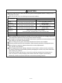 7
7
-
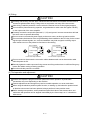 8
8
-
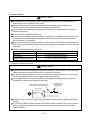 9
9
-
 10
10
-
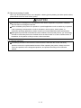 11
11
-
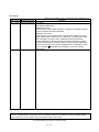 12
12
-
 13
13
-
 14
14
-
 15
15
-
 16
16
-
 17
17
-
 18
18
-
 19
19
-
 20
20
-
 21
21
-
 22
22
-
 23
23
-
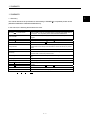 24
24
-
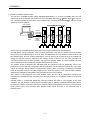 25
25
-
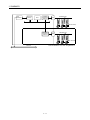 26
26
-
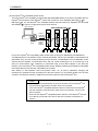 27
27
-
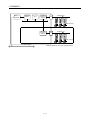 28
28
-
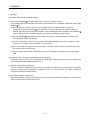 29
29
-
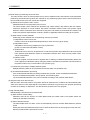 30
30
-
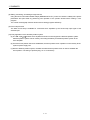 31
31
-
 32
32
-
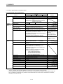 33
33
-
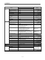 34
34
-
 35
35
-
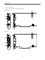 36
36
-
 37
37
-
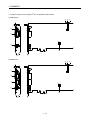 38
38
-
 39
39
-
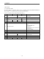 40
40
-
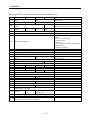 41
41
-
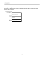 42
42
-
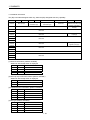 43
43
-
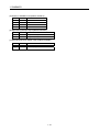 44
44
-
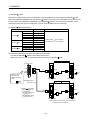 45
45
-
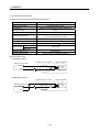 46
46
-
 47
47
-
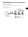 48
48
-
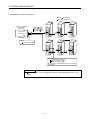 49
49
-
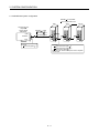 50
50
-
 51
51
-
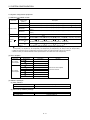 52
52
-
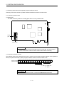 53
53
-
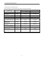 54
54
-
 55
55
-
 56
56
-
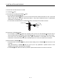 57
57
-
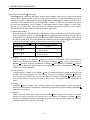 58
58
-
 59
59
-
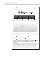 60
60
-
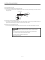 61
61
-
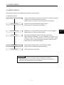 62
62
-
 63
63
-
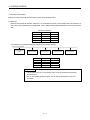 64
64
-
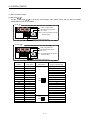 65
65
-
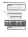 66
66
-
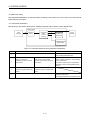 67
67
-
 68
68
-
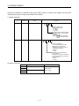 69
69
-
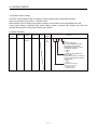 70
70
-
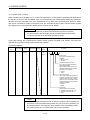 71
71
-
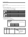 72
72
-
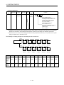 73
73
-
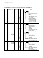 74
74
-
 75
75
-
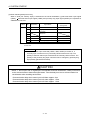 76
76
-
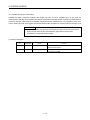 77
77
-
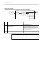 78
78
-
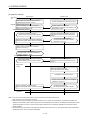 79
79
-
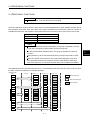 80
80
-
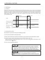 81
81
-
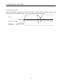 82
82
-
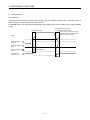 83
83
-
 84
84
-
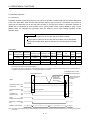 85
85
-
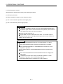 86
86
-
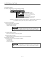 87
87
-
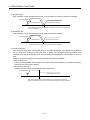 88
88
-
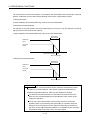 89
89
-
 90
90
-
 91
91
-
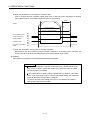 92
92
-
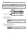 93
93
-
 94
94
-
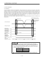 95
95
-
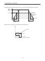 96
96
-
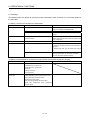 97
97
-
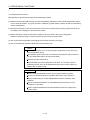 98
98
-
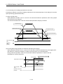 99
99
-
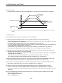 100
100
-
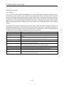 101
101
-
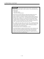 102
102
-
 103
103
-
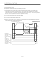 104
104
-
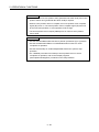 105
105
-
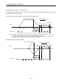 106
106
-
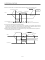 107
107
-
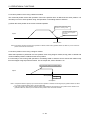 108
108
-
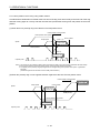 109
109
-
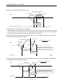 110
110
-
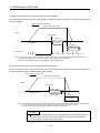 111
111
-
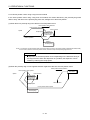 112
112
-
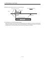 113
113
-
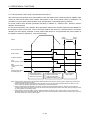 114
114
-
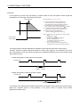 115
115
-
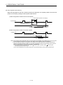 116
116
-
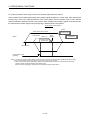 117
117
-
 118
118
-
 119
119
-
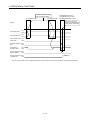 120
120
-
 121
121
-
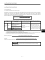 122
122
-
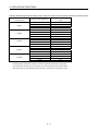 123
123
-
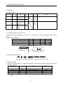 124
124
-
 125
125
-
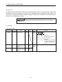 126
126
-
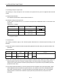 127
127
-
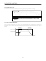 128
128
-
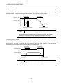 129
129
-
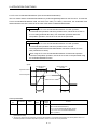 130
130
-
 131
131
-
 132
132
-
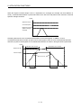 133
133
-
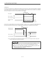 134
134
-
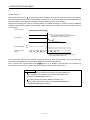 135
135
-
 136
136
-
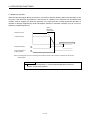 137
137
-
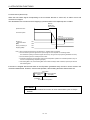 138
138
-
 139
139
-
 140
140
-
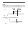 141
141
-
 142
142
-
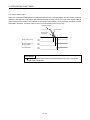 143
143
-
 144
144
-
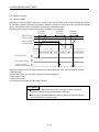 145
145
-
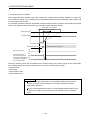 146
146
-
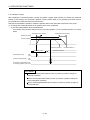 147
147
-
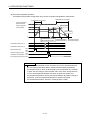 148
148
-
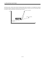 149
149
-
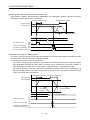 150
150
-
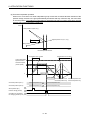 151
151
-
 152
152
-
 153
153
-
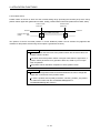 154
154
-
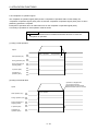 155
155
-
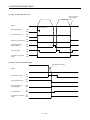 156
156
-
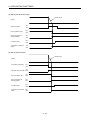 157
157
-
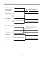 158
158
-
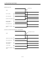 159
159
-
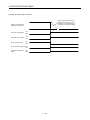 160
160
-
 161
161
-
 162
162
-
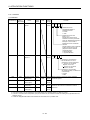 163
163
-
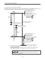 164
164
-
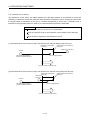 165
165
-
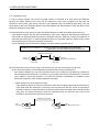 166
166
-
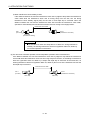 167
167
-
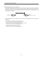 168
168
-
 169
169
-
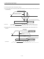 170
170
-
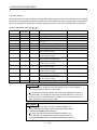 171
171
-
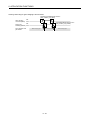 172
172
-
 173
173
-
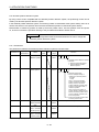 174
174
-
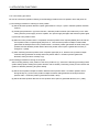 175
175
-
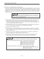 176
176
-
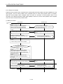 177
177
-
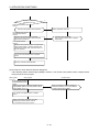 178
178
-
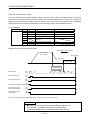 179
179
-
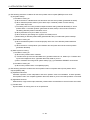 180
180
-
 181
181
-
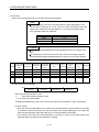 182
182
-
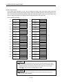 183
183
-
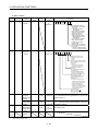 184
184
-
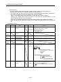 185
185
-
 186
186
-
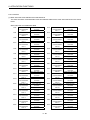 187
187
-
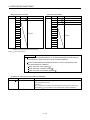 188
188
-
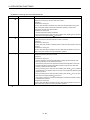 189
189
-
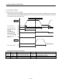 190
190
-
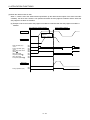 191
191
-
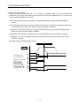 192
192
-
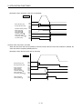 193
193
-
 194
194
-
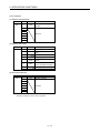 195
195
-
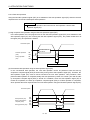 196
196
-
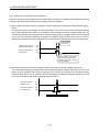 197
197
-
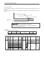 198
198
-
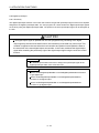 199
199
-
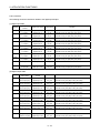 200
200
-
 201
201
-
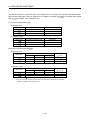 202
202
-
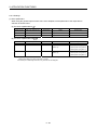 203
203
-
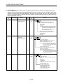 204
204
-
 205
205
-
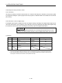 206
206
-
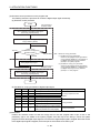 207
207
-
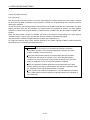 208
208
-
 209
209
-
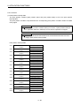 210
210
-
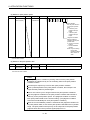 211
211
-
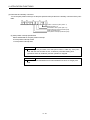 212
212
-
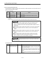 213
213
-
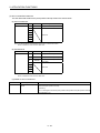 214
214
-
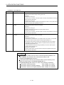 215
215
-
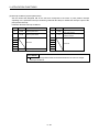 216
216
-
 217
217
-
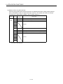 218
218
-
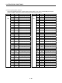 219
219
-
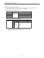 220
220
-
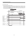 221
221
-
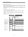 222
222
-
 223
223
-
 224
224
-
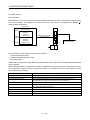 225
225
-
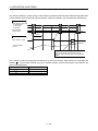 226
226
-
 227
227
-
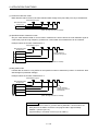 228
228
-
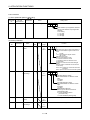 229
229
-
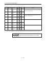 230
230
-
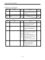 231
231
-
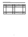 232
232
-
 233
233
-
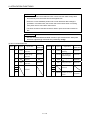 234
234
-
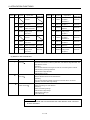 235
235
-
 236
236
-
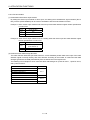 237
237
-
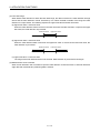 238
238
-
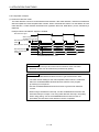 239
239
-
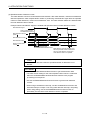 240
240
-
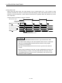 241
241
-
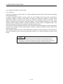 242
242
-
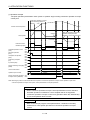 243
243
-
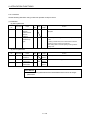 244
244
-
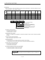 245
245
-
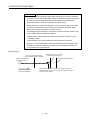 246
246
-
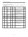 247
247
-
 248
248
-
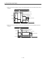 249
249
-
 250
250
-
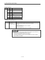 251
251
-
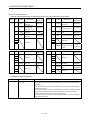 252
252
-
 253
253
-
 254
254
-
 255
255
-
 256
256
-
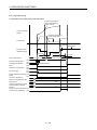 257
257
-
 258
258
-
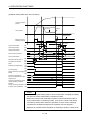 259
259
-
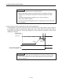 260
260
-
 261
261
-
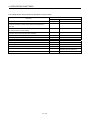 262
262
-
 263
263
-
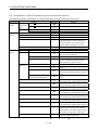 264
264
-
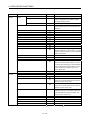 265
265
-
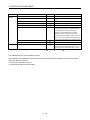 266
266
-
 267
267
-
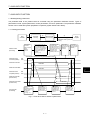 268
268
-
 269
269
-
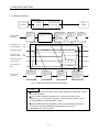 270
270
-
 271
271
-
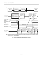 272
272
-
 273
273
-
 274
274
-
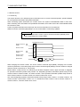 275
275
-
 276
276
-
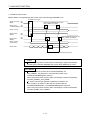 277
277
-
 278
278
-
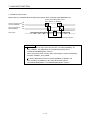 279
279
-
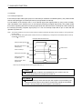 280
280
-
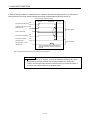 281
281
-
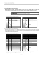 282
282
-
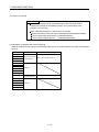 283
283
-
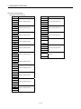 284
284
-
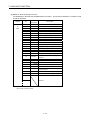 285
285
-
 286
286
-
 287
287
-
 288
288
-
 289
289
-
 290
290
-
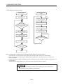 291
291
-
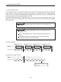 292
292
-
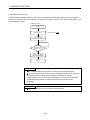 293
293
-
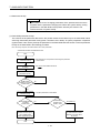 294
294
-
 295
295
-
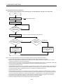 296
296
-
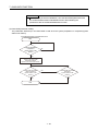 297
297
-
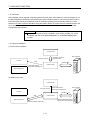 298
298
-
 299
299
-
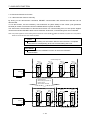 300
300
-
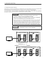 301
301
-
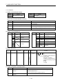 302
302
-
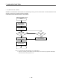 303
303
-
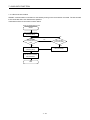 304
304
-
 305
305
-
 306
306
-
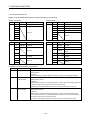 307
307
-
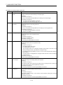 308
308
-
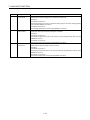 309
309
-
 310
310
-
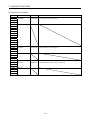 311
311
-
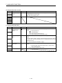 312
312
-
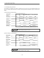 313
313
-
 314
314
-
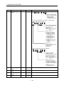 315
315
-
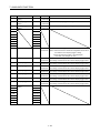 316
316
-
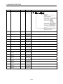 317
317
-
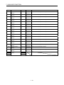 318
318
-
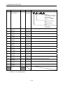 319
319
-
 320
320
-
 321
321
-
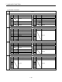 322
322
-
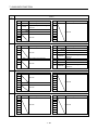 323
323
-
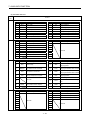 324
324
-
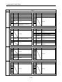 325
325
-
 326
326
-
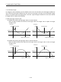 327
327
-
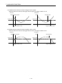 328
328
-
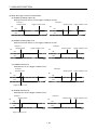 329
329
-
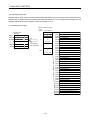 330
330
-
 331
331
-
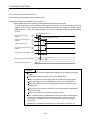 332
332
-
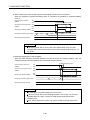 333
333
-
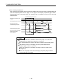 334
334
-
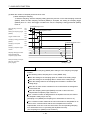 335
335
-
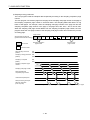 336
336
-
 337
337
-
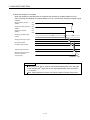 338
338
-
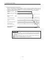 339
339
-
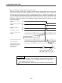 340
340
-
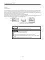 341
341
-
 342
342
-
 343
343
-
 344
344
-
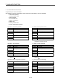 345
345
-
 346
346
-
 347
347
-
 348
348
-
 349
349
-
 350
350
-
 351
351
-
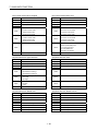 352
352
-
 353
353
-
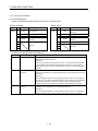 354
354
-
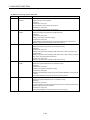 355
355
-
 356
356
-
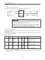 357
357
-
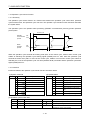 358
358
-
 359
359
-
 360
360
-
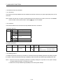 361
361
-
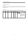 362
362
-
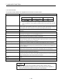 363
363
-
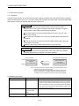 364
364
-
 365
365
-
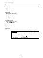 366
366
-
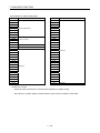 367
367
-
 368
368
-
 369
369
-
 370
370
-
 371
371
-
 372
372
-
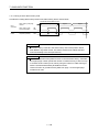 373
373
-
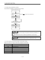 374
374
-
 375
375
-
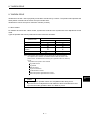 376
376
-
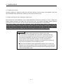 377
377
-
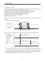 378
378
-
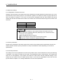 379
379
-
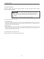 380
380
-
 381
381
-
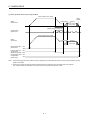 382
382
-
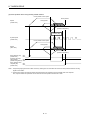 383
383
-
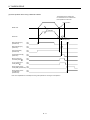 384
384
-
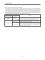 385
385
-
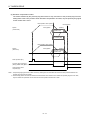 386
386
-
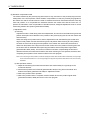 387
387
-
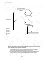 388
388
-
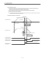 389
389
-
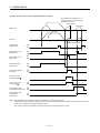 390
390
-
 391
391
-
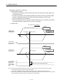 392
392
-
 393
393
-
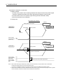 394
394
-
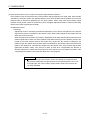 395
395
-
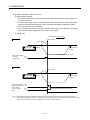 396
396
-
 397
397
-
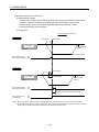 398
398
-
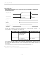 399
399
-
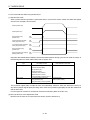 400
400
-
 401
401
-
 402
402
-
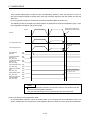 403
403
-
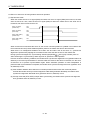 404
404
-
 405
405
-
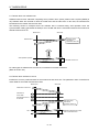 406
406
-
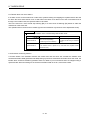 407
407
-
 408
408
-
 409
409
-
 410
410
-
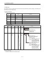 411
411
-
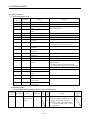 412
412
-
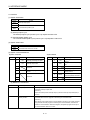 413
413
-
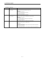 414
414
-
 415
415
-
 416
416
-
 417
417
-
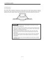 418
418
-
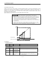 419
419
-
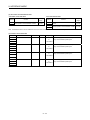 420
420
-
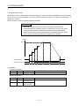 421
421
-
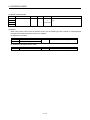 422
422
-
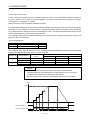 423
423
-
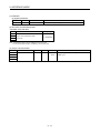 424
424
-
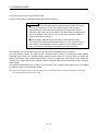 425
425
-
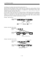 426
426
-
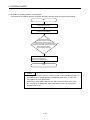 427
427
-
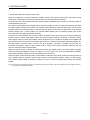 428
428
-
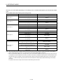 429
429
-
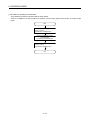 430
430
-
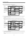 431
431
-
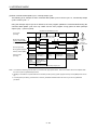 432
432
-
 433
433
-
 434
434
-
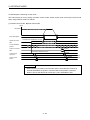 435
435
-
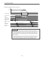 436
436
-
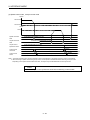 437
437
-
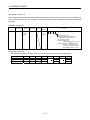 438
438
-
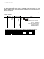 439
439
-
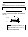 440
440
-
 441
441
-
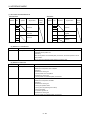 442
442
-
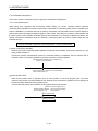 443
443
-
 444
444
-
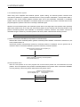 445
445
-
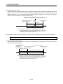 446
446
-
 447
447
-
 448
448
-
 449
449
-
 450
450
-
 451
451
-
 452
452
-
 453
453
-
 454
454
-
 455
455
-
 456
456
-
 457
457
-
 458
458
-
 459
459
-
 460
460
-
 461
461
-
 462
462
-
 463
463
-
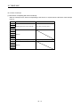 464
464
-
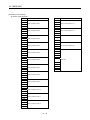 465
465
-
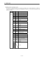 466
466
-
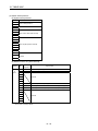 467
467
-
 468
468
-
 469
469
-
 470
470
-
 471
471
-
 472
472
-
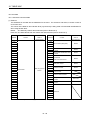 473
473
-
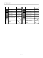 474
474
-
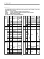 475
475
-
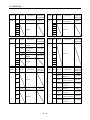 476
476
-
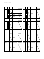 477
477
-
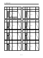 478
478
-
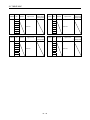 479
479
-
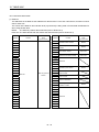 480
480
-
 481
481
-
 482
482
-
 483
483
-
 484
484
-
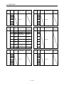 485
485
-
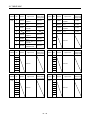 486
486
-
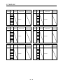 487
487
-
 488
488
-
 489
489
-
 490
490
-
 491
491
-
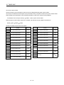 492
492
-
 493
493
-
 494
494
-
 495
495
-
 496
496
-
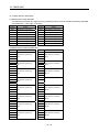 497
497
-
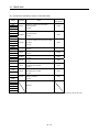 498
498
-
 499
499
-
 500
500
-
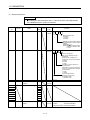 501
501
-
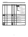 502
502
-
 503
503
-
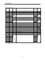 504
504
-
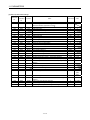 505
505
-
 506
506
-
 507
507
-
 508
508
-
 509
509
-
 510
510
-
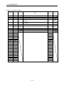 511
511
-
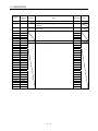 512
512
-
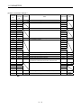 513
513
-
 514
514
-
 515
515
-
 516
516
-
 517
517
-
 518
518
-
 519
519
-
 520
520
-
 521
521
-
 522
522
-
 523
523
-
 524
524
-
 525
525
-
 526
526
-
 527
527
-
 528
528
-
 529
529
-
 530
530
-
 531
531
-
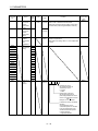 532
532
-
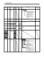 533
533
-
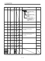 534
534
-
 535
535
-
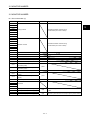 536
536
-
 537
537
-
 538
538
-
 539
539
-
 540
540
-
 541
541
-
 542
542
-
 543
543
-
 544
544
-
 545
545
-
 546
546
-
 547
547
-
 548
548
-
 549
549
-
 550
550
-
 551
551
-
 552
552
-
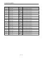 553
553
-
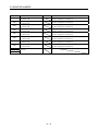 554
554
-
 555
555
-
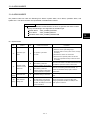 556
556
-
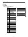 557
557
-
 558
558
-
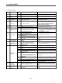 559
559
-
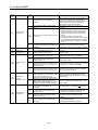 560
560
-
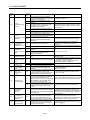 561
561
-
 562
562
-
 563
563
-
 564
564
-
 565
565
-
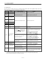 566
566
-
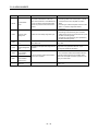 567
567
-
 568
568
-
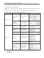 569
569
-
 570
570
-
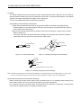 571
571
-
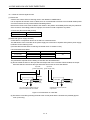 572
572
-
 573
573
-
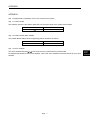 574
574
-
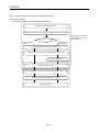 575
575
-
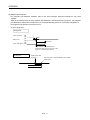 576
576
-
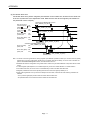 577
577
-
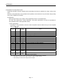 578
578
-
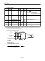 579
579
-
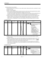 580
580
-
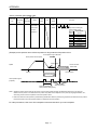 581
581
-
 582
582
-
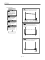 583
583
-
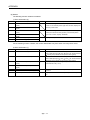 584
584
-
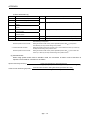 585
585
-
 586
586
-
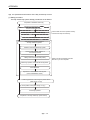 587
587
-
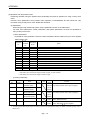 588
588
-
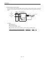 589
589
-
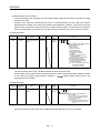 590
590
-
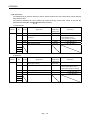 591
591
-
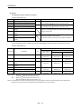 592
592
-
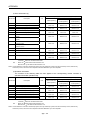 593
593
-
 594
594
-
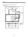 595
595
-
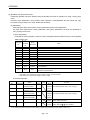 596
596
-
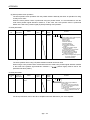 597
597
-
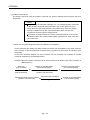 598
598
-
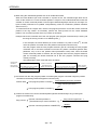 599
599
-
 600
600
-
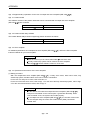 601
601
-
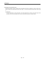 602
602
-
 603
603
-
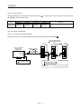 604
604
-
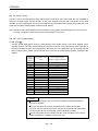 605
605
-
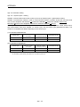 606
606
-
 607
607
-
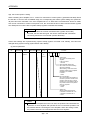 608
608
-
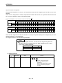 609
609
-
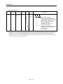 610
610
-
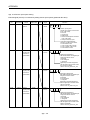 611
611
-
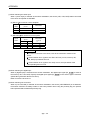 612
612
-
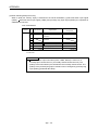 613
613
-
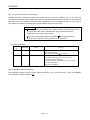 614
614
-
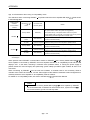 615
615
-
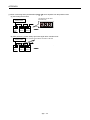 616
616
-
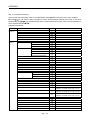 617
617
-
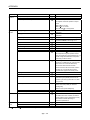 618
618
-
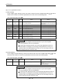 619
619
-
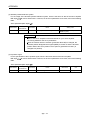 620
620
-
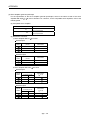 621
621
-
 622
622
-
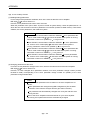 623
623
-
 624
624
-
 625
625
-
 626
626
-
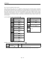 627
627
-
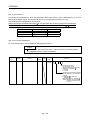 628
628
-
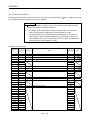 629
629
-
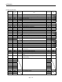 630
630
-
 631
631
-
 632
632
-
 633
633
-
 634
634
-
 635
635
-
 636
636
-
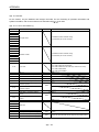 637
637
-
 638
638
-
 639
639
-
 640
640
-
 641
641
-
 642
642
-
 643
643
-
 644
644
-
 645
645
-
 646
646
-
 647
647
-
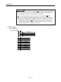 648
648
-
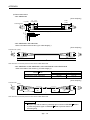 649
649
-
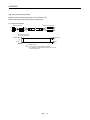 650
650
-
 651
651
-
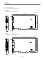 652
652
-
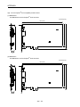 653
653
-
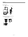 654
654
-
 655
655
-
 656
656
-
 657
657
-
 658
658


Mitsubishi Electronics Sleep Apnea Machine MR-MC211 User manual
- Type
- User manual
Ask a question and I''ll find the answer in the document
Finding information in a document is now easier with AI
Related papers
-
Mitsubishi Electric MR-J2M-P8B User manual
-
-
-
Mitsubishi Q173CPU(N)/Q172CPU(N) User manual
-
 Mitsubishi Electronics Video Gaming Accessories Q170MCPU User manual
-
Mitsubishi MOTION CONTROLLERS Q172DCPU User manual
-
-
-

Other documents
-
Mitsubishi Electric AC Servos Operating instructions
-
-
-
-
Mitsubishi Electric PUY-A-NHA3-BS User manual
-
-
-
-
-