Page is loading ...

Instruction Manual
LIQ_MAN_6081-P
Rev. B
February 2014
6081-P
Wireless pH/ORP Transmitter

Essential Instructions
Read this page before proceeding
Rosemount Analytical designs, manufactures, and tests its products to meet many national and international
standards. Because these instruments are sophisticated technical products, you must properly install, use, and
maintain them to ensure they continue to operate within their normal specications. The following instructions
must be adhered to and integrated into your safety program when installing, using, and maintaining Rosemount
Analytical products. Failure to follow the proper instructions may cause any one of the following situations to
occur: Loss of life; personal injury; property damage; damage to this instrument; and warranty invalidation.
• Read all instructions prior to installing, operating, and servicing the product. If this Instruction Manual is not the
correct manual, telephone 1-800-654-7768 and the requested manual will be provided. Save this Instruction
Manual for future reference.
• If you do not understand any of the instructions, contact your Rosemount representative for clarication.
• Follow all warnings, cautions, and instructions marked on and supplied with the product.
• Inform and educate your personnel in the proper installation, operation, and maintenance of the product.
• Install your equipment as specied in the Installation Instructions of the appropriate Instruction Manual and per
applicable local and national codes. Connect all products to the proper electrical and pressure sources.
• To ensure proper performance, use qualied personnel to install, operate, update, program, and maintain the
product.
• When replacement parts are required, ensure that qualied people use replacement parts specied by
Rosemount. Unauthorized parts and procedures can affect the product’s performance and place the safe
operation of your process at risk. Look alike substitutions may result in re, electrical hazards, or improper
operation.
• Ensure that all equipment doors are closed and protective covers are in place, except when maintenance is
being performed by qualied persons, to prevent electrical shock and personal injury.
NOTICE
The Rosemount 6081 and all other wireless devices should be installed only after the 1420 Wireless Gateway has been in-
stalled and is functioning properly. Wireless devices should also be powered up in order of proximity from the 1420 Wireless
Gateway, beginning with the closest. This will result in a simpler and faster network installation.
NOTICE
Shipping considerations for wireless products (Power Modules):
The unit was shipped to you without the power module installed. Please remove the power modules from the unit prior to
shipping.
Primary lithium power modules are regulated in transportation by the U. S. Department of Transportation, and are also
covered by IATA (International Air Transport Association), ICAO (International Civil Aviation Organization), and ARD (Europe-
an Ground Transportation of Dangerous Goods). It is the responsibility of the shipper to ensure compliance with these or any
other local requirements. Please consult current regulations and requirements before shipping.
The power module with the wireless unit contains two “C” size primary lithium/thionyl chloride power sources.
Each power module contains approximately 5 grams in each pack. Under normal conditions, the power module
materials are self-contained and are not reactive as long as the power modules and the pack integrity are
maintained. Care should be taken to prevent thermal, electrical or mechanical damage. Contacts should be
protected to prevent premature discharge.
Power module hazards remain when cells are discharged.
Power modules should be stored in a clean and dry area. For maximum power module life, storage temperature
should not exceed 30 °C.
CAUTION: SENSOR/PROCESS APPLICATION COMPATIBILITY
If a 375 Universal Hart
®
Communicator is used with these transmitters, the software within the 375 may require modica-
tion. If a software modication is required, please contact your local Emerson Process Management Service Group or Nation-
al Response Center at 1-800-654-7768.

About This Document
This manual contains instructions for installation and operation of 398R and 398RVP TUpH
Retractable pH/ORP Sensors. The following list provides notes concerning all revisions of this
document.
Rev. Level Date Notes
A 11/08
This is the initial release of the product manual. The manual has
been reformatted to reflect the Emerson documentation style and
updated to reflect any changes in the product offering. This manual
contains information on the HART Smart 6081-P.
B 2/14 FM Certication added. Updated document to reect Emerson’s latest
documentations style.

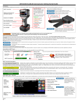
Quick Start Guide
For 6081 Wireless pH Transmitter
1. Refer to Section 2.0 Installation for installation instructions.
2 . Wire the pH or ORP sensor to the transmitter. Refer to the sensor instruction sheet for details.
3. Once the connections are secure and veried, install the Power Module to power to the
transmitter.
4. When the transmitter is powered up for the rst time, Quick Start screens appear. Using Quick
Start is easy.
a. A blinking eld shows the position of the cursor.
b. Use the ◄ or ► key to move the cursor left or right. Use the ▲ or ▼ key to move the
cursor up or down or to increase or decrease the value of a digit. Use the ▲ or ▼ key to
move the decimal point.
c. Press ENTER to store a setting. Press EXIT to leave without storing changes. Pressing
EXIT also returns the display to the previous screen.
5. Choose a local language.
6. Choose measurement: pH, ORP, or Redox.
7. Choose preamplier location. Select Xmtr to use the integral preamplier in the transmitter.
8. Choose Off or On for displayed diagnostics.
9. Select measurement update rate. Select ENTER to choose an update rate of 1 minute or enter
a value from 1 second to 10 minutes.
10. Choose temperature units: °C or °F
11. Choose Yes to Setup the Wireless Network or No if the Network ID and the Join Key have
already been entered.
12. Enter the 5-digit Wireless Network ID. This ID number must match the Network ID of the
1420 Wireless Gateway.
13. Enter the 8-digit Network Join Key number 1 of 4 to match the Model 1420 Wireless Gateway.
See the Note below for clarication.
14. Enter Network Join Key numbers 2, 3, and 4 to match the Model 1420 Wireless Gateway.
15. The transmitter will exit Quick Start and display the live measurement screen.
16. To change the Network ID or Join Key, HART address, or measurement-related settings from
the default values, and to set security codes, press MENU. Select Program and follow the
prompts. Refer to the appropriate menu tree.
17. To return the transmitter to default settings, choose Reset Analyzer in the Program menu.
Note regarding Wireless Device Configuration
In order to communicate with the 1420 Wireless Gateway, and ultimately the Information
System, the transmitter must be congured to communicate with the wireless network. This step
is the wireless equivalent of connecting wires from a transmitter to the information system.
Using a Field Communicator or AMS, enter the Network ID and Join Key so that they match the
Network ID and Join Key of the gateway and other devices in the network. The Network Join Key
consists of four (4) blocks, each with an eight digit code. The code of each block must match its
corresponding block in the 1420 in order for the 6081 to join the network.
If the Network ID and Join Key are not identical, the transmitter will not communicate with the
network. The Network ID and Join Key may be obtained from the 1420 Wireless Gateway on the
Setup>Network>Settings page on the web server.
The nal device network conguration piece is the Update Rate. This by default is one (1) minute.
This may be changed at commissioning, or at any time via AMS or the 1420 Wireless Gateway’s
web server. The Update Rate should be between 1 second and 10 minutes.
When device conguration is completed, remove the power module and replace the rear cover
of the transmitter until the time of actual live installation in the process. Tighten the cover to the
proper tension for safety approvals.

Quick Start
Menu
English Francais
Espanol >>
Deutsch Italiano
Portuguese >>
Measure? pH
Redox ORP
Use Preamp in?
Xmtr Sensor
Diagnostics?
On Off
Measure update
rate: 1min
Temperature in?
°C °F
Setup Wireless
Network? Yes No
Wireless Network
HART Poll Address
Network ID:
00000
Network Join Key
1 of 4: 00000000
Network Join Key
2 of 4: 00000000
Network Join Key
3 of 4: 00000000
Network Join Key
4 of 4: 00000000
Wireless Network
HART Poll Address
HART Polling
Address: 00

Section Title Instruction Manual
February 2014 LIQ_MAN_6081-P
Figure 1-1 Menu Tree for 6081 pH Wireless Transmitter

Instruction Manual Section Title
LIQ_MAN_6081-P February 2014
Contents i
Contents
Section 1: Description and Specifications
1.1 Features and Application ......................................................................................1
1.2 Specications - General ............................................................................ ......... .1
1.3 Specications - Wireless ....................................................................................... 1
1.4 Specications - Functional ....................................................................................2
1.5 Product Certications ...........................................................................................3
1.6 HART Communications ........................................................................................3
1.7 Asset Management Solutions ...............................................................................3
Section 2: Installation
2.1 Considerations ....................................................................................................5
2.2 Unpacking and Inspection ...................................................................................5
2.3 Pre-Installation set up .......................................................................................... 5
2.4 Mechanical Installation ........................................................................................6
2.5 Ground the Transmitter .......................................................................................6
2.6 Power Module Installation ...................................................................................9
Section 3: Wiring
3.1 General Information ........................................................................................... 11
3.2 Sensor Wiring .................................................................................................... 11
Section 4: Intrinsically Safe Installation
4.1 Instrinsically Safe Installation ..............................................................................13
Section 5: Commissioning
5.1 Network Communications ................................................................................. 17
5.2 Device Network Conguration ...........................................................................17
5.3 Verify Operation ................................................................................................ 17
Section 6: Display and Operation
6.1 Display ...............................................................................................................19
6.2 Keypad .............................................................................................................. 20
6.3 Menu – pH ........................................................................................................ 20
6.4 Information Screen Messages ...........................................................................20
6.5 Security ............................................................................................................. 20
Section 7: Operation with 375 Hart Communicator
7.1 Note on 375 HART COmmunicator ....................................................................21
7.2 Connecting the HART Communicator ................................................................21
7.3 Operation ..........................................................................................................22
Section 8: Programming the Transmitter
8.1 General .............................................................................................................. 23
8.2 Changing Start-up Settings ................................................................................ 23
8.3 Choosing and Conguring the Analytical Measurement ..................................... 23
8.4 Choosing Temperature Units and Manual or Auto Temperature Compensation . 24
8.5 Setting a Security Code ..................................................................................... 24
8.6 Making HART-Related Settings ........................................................................... 25
8.7 Resetting Factory Calibration and Factory Default Settings ............................... 25
8.8 Selecting a Default Screen and Screen Contrast ................................................ 25
8.9 Choosing a Display Timeout ............................................................................... 26

Section Title Instruction Manual
February 2014 LIQ_MAN_6081-P
ii Contents
Section 9: Calibration of Temperature
9.1 Introduction ......................................................................................................27
9.2 Calibration - Temperature ................................................................................. 27
Section 10: Calibration –pH and ORP
10.1 Introduction ......................................................................................................29
10.2 Procedure – Auto Buffer Calibration .................................................................30
10.3 Procedure – Manual Two-Point Buffer Calibration ..............................................31
10.4 Procedure – Standardization ............................................................................31
10.5 Procedure – Entering a Known Slope Value .......................................................32
10.6 ORP Calibration ................................................................................................32
Section 11: Maintenance
11.1 Overview ...........................................................................................................33
11.2 Transmitter Maintenance ...................................................................................33
11.3 pH Sensor Maintenance ....................................................................................33
11.4 ORP Sensor Maintenance ...................................................................................34
11.5 Calibration ........................................................................................................35
11.6 Power Module Replacement ..............................................................................35
Section 12: Return of Material
Return of Material .............................................................................................37
Contents (continued)
List of Figures
2-1 Wall Mounting Installation for 6081 ..................................................................................7
2-2 Pipe Mounting Installation for 6081 ................................................................................... 8
2-3 Removing Rear Cover ........................................................................................................ 9
2-4 Power Module Warning Label ............................................................................................ 9
2-5 Installing the Power Module .............................................................................................. 9
2-6 Securing the rear cover .................................................................................................... 10
3-1 6081 Sensor Wiring and Connection Points ..................................................................... 11
4-1 FM IS Installation ............................................................................................................. 13
4-2 CSA IS Installation ............................................................................................................ 14
4-3 ATEX IS Installation ..........................................................................................................15
6-1 Displays During Normal Operation .................................................................................. 19
6-2 6081 Keypad .................................................................................................................. 20
7-1 6081 Sensor Wiring and Connection Points .................................................................... 21
10-1 Calibration Slope and Offset ...........................................................................................30
11-1 Checking the Potential of the Reference Electrode .......................................................... 34

Description and Specications 1
Instruction Manual Description and Specifications
LIQ_MAN_6081-P February 2014
Section 1: Description and Specications
• High accuracy and reliability for monitoring applications
• Self-organizing network for high data reliability and network stability
• Industry Leading wireless Security
• Compatible with 1420 Wireless gateway and Emerson Process Management WirelessHART
TM
networks
• Easy to read two-line display with easy to use menus
• WirelessHART 7 Digital Communications
• SMART Sensor Enabled
• Continuous diagnostics monitor sensor performance and health
1.1 Description and Specifications
The 6081-P transmitter is ideal for monitoring applications, especially in hard-to-reach or cost-
prohibitive locations. The 6081-P measures pH and ORP and is compatible with most Rosemount
Analytical pH and ORP sensors. The transmitter has a rugged, cast aluminum weatherproof
and corrosion-resistant enclosure (NEMA 4X). The transmitter includes a two-line 16-character
display with simple and intuitive menu screens. Plain language prompts in six (6) local languages
guide the user through the programming and calibration procedures. The 6081 is compatible
with non-preamp pH and ORP sensors and SMART pH sensors from Rosemount Analytical.
Installation and start-up of the 6081-P wireless transmitter is simple. Just power the
6081-P and assign it to a wireless network with a 1420 Gateway. The unit will auto-locate the
most efcient path to the host and will begin transmitting measurement data immediately via 2.4
GHz wireless communications. The Self-Organizing Network ensures exceptional data reliability
and network stability. All of Emerson Process Management’s wireless devices employ Encryption,
Authentication, Verication, Anti-Jamming and Key Management to ensure data transmission and
security. Rosemount Analytical devices include intelligent power management to reduce power
consumption and extend power module life while delivering highly reliable measurements with
rich HART data and diagnostic information. HART digital communication allows access to AMS
(Asset Management Solutions) for live process variables, useful diagnostics and troubleshooting
information.
1.2 Specifications - General
Enclosure: Cast aluminum. NEMA 4X.
Dimensions: 6.55” x 5.40” x 5.15” (166mm x 137mm x 131mm)
Conduit Openings: 3/4” FNPT
Ambient Temperature: 32 to 122°F (0 to 50°C)
Storage Temperature: -4 to 158°F (-20 to 70°C)
Relative Humidity: 0 to 95% (non-condensing)
Weight/Shipping Weight: 7 lbs/8 lbs (3.2/3.6 kg)
RFI/EMI: EN-61326
Digital Communications: HART 7 WirelessHART
1.2.1 Specications - Wireless
Output: Wireless enabled HART 7.0
Transmit Rate: User selectable.
Antenna: PBT/PC integrated omni-directional antenna
1.3 Specifications - Wireless
Output: WirelessHART V7
Transmit Rate: User selectable, 1/sec. to 1/60 min (via 1420 wireless Gateway or AMS)
Measurement update rate: 1/sec. to 1/10 min
Antenna: PBT/PC integrated omni-directional antenna

Description and Specifications Instruction Manual
February 2014 LIQ_MAN_6081-P
2 Description and Specications
Radio Frequency: 2.4 GHz DSSS
Transmission distance - line of sight: about 600 ft (ideal RF conditions and power
module condition)
Power: Lithium thionyl chloride long life power module
1.4 Functional Specifications
pH Range: 0 to 14
ORP Range: -1400 to +1400mV
Compatible with Rosemount Analytical SMART pH sensors calibrations/standardization:
The automatic buffer recognition uses stored buffer values and their temperature curves for
the most common buffer standards available worldwide. The transmitter also performs a
stabilization check on the sensor in each buffer.
A manual two-point calibration is made by immersing the sensor in two different buffer
solutions and entering the pH values. The microprocessor automatically calculates the slope
which is used for self-diagnostics. An error message will be displayed if the pH sensor is faulty.
This slope can be read on the display and/or manually adjusted if desired.
An on-line one-point process standardization is accomplished by entering the pH or ORP
value of a grab sample.
The following calibration methods are supported:
- Two point calibration with Low and High buffer (pH only)
- Two point calibration with Automatic Buffer recognition (pH only)
- Single point standardization
- Single point Temperature Adjustment
- Automatic calibration upon live connection to RAI SMART pH sensors and upload of
stored cal data to transmitter
Automatic Temperature Compensation: External 3-wire Pt100 RTD or Pt1000 RTD located in
the sensor, compensates the pH reading for temperature uctuations. Compensation covers
the range -10 to 150 °C (14 to 302 °F). Manual temperature compensation is also selectable.
Accuracy: ±1 mV @ 25 °C ±0.01 pH
Repeatability: ±1 mV @ 25 °C ± 0.01 pH
Information and Status: Information screens display faults and warnings, radio transmission
status, network ID number, Power Module voltage, transmitter model, and software version.
Diagnostics: The internal diagnostics can detect:
RTD Failure
Glass Low Failure
Glass High Failure
Broken Glass Fault
Reference High Failure
CPU Error
High Temperature Warning
Low Temperature Warning
Glass Impedance High Warning
Glass Impedance Low Warning
Reference Impedance High Warning
EEPROM Warning
Sense Line Open Warning
Factory Cal Warning
Keyboard Warning
Once a fault or warning is detected, the display will show a message describing the problem.
Temperature Range: -10 to 150°C (PT100 and PT1000)
Display: 2-line, 16 character display supports display of pH and mV units. Display shows
temperature.
Approvals:
RFI/EMI: EN-61326
NOTE on ESD
“Change due to disturbance caused by electrostatic discharge will be less than 0.2 pH.”

Instruction Manual Description and Specifications
LIQ_MAN_6081-P February 2014
Description and Specications 3
1.5 Product Certifications
Telecommunication Compliance
All wireless devices require certication to ensure that they adhere to regulations regarding the
use of the RF spectrum. Nearly every country requires this type of product certication. Emerson
is working with governmental agencies around the world to supply fully compliant products and
remove the risk of violating country directives or laws governing wireless device usage.
FCC and IC
This device complies with Part 15 of the FCC Rules. Operation is subject to the following
conditions: This device may not cause harmful interference, this device must accept any
interference received, including interference that may cause undesired operation.
This device must be installed to ensure a minimum antenna separation distance of 20 cm from all
persons.
1.6 HART Communications
1.6.1 Overview of HART Communication
HART (highway addressable remote transducer) V.7 supports a wireless digital communication
system.
The HART protocol, originally developed by Fisher-Rosemount, is now overseen by the
independent HART Communication Foundation. The Foundation ensures that all HART devices
can communicate with one another. For more information about HART communications, call
the HART Communication Foundation at (512) 794-0369. The internet address is http://www.
hartcomm.org.
1.6.2 HART Interface Devices
HART communicators allow the user to view measurement data (pH, ORP and temperature),
program the transmitter, and download information from the transmitter for transfer to a
computer for analysis. Downloaded information can also be sent to another HART transmitter.
Either a hand-held communicator, such as the Rosemount Model 375, or a computer can be used.
HART interface devices operate fromthe HART taps inside the rear enclosure.
If your communicator does not recognize the Model 6081 pH/ORP transmitter, the device
description library may need updating. Call the manufacturer of your HART communication
device for updates.
1.7 Asset Management Solutions
Asset Management Solutions (AMS) is software that helps plant personnel better monitor the
performance of analytical instruments, pressure and temperature transmitters, and control
valves. Continuous monitoring means maintenance personnel can anticipate equipment failures
and plan preventative measures before costly breakdown maintenance is required.
AMS uses remote monitoring. The operator, sitting at a computer, can view measurement data,
change program settings, read diagnostic and warning messages, and retrieve historical data
from any HART-compatible device, including the Model 6081-P transmitter. Although AMS
allows access to the basic functions of any HART compatible device, Rosemount Analytical
has developed additional software for that allows access to all features of the Model 6081-P
transmitter.
AMS can play a central role in plant quality assurance and quality control. Using AMS Audit Trail,
plant operators can track calibration frequency and results as well as warnings and diagnostic
messages. The information is available to Audit Trail whether calibrations were done using the
infrared remote controller, the Model 375 HART communicator, or AMS software.
AMS operates in Windows 95. AMS communicates through a HART-compatible modem with
any HART transmitters, including those from other manufacturers. AMS is also compatible with
FoundationÔ Fieldbus, which allows future upgrades to Fieldbus instruments.
Rosemount Analytical AMS windows provide access to all transmitter measurement and
conguration variables. The user can read raw data, nal data, and program settings and can
recongure the transmitter from anywhere in the plant.

4 Description and Specications
Description and Specifications Instruction Manual
February 2014 LIQ_MAN_6081-P
This page left blank intentionally

Instruction Manual Installation
LIQ_MAN_6081-P February 2014
Installation 5
Section 2: Installation
2.1 Considerations
The transmitter can be commissioned before or after installation. It may be useful to commission
it on the bench, before installation, to ensure proper operation and to become familiar with
its functionality. When applicable, make sure the instruments are installed in accordance with
intrinsically safe or non-incendive eld wiring practices. The device will be powered whenever the
power module is installed. To avoid depleting the power module, make sure it is removed when
the device is not in use.
Power module
The 6081 is battery powered. The power module with the wireless unit contains 2 “C” size
primary lithium/thionyl chloride batteries. Each power module contains approximately .5 grams
of lithium. Under normal conditions, the power module materials are self-contained and are not
reactive as long as the power module integrity is maintained. Care should be taken to prevent
thermal, electrical or mechanical damage. Contacts should be protected to prevent premature
discharge. Use caution when handling the power module. The power module may be damaged if
dropped from heights in excess of 20 feet.
Sensor
Make sensor connections through the cable entry in the enclosure. Be sure to provide adequate
clearance for cover removal.
Environmental
Verify that the operating atmosphere of the transmitter is consistent with the appropriate
hazardous locations certications.
2.2 Unpacking and Inspection
Inspect the shipping container. If it is damaged, contact the shipper immediately for instructions.
Save the box. If there is no apparent damage, remove the transmitter. Be sure all items shown on
the packing list are present. If items are missing, immediately notify Rosemount Analytical.
Save the shipping container and packaging. They can be reused if it is later necessary to return
the transmitter to the factory.
2.3 Pre-Installation Set-up
2.3.1 Temperature Element
The 6081-P pH/ORP transmitter is compatible with sensors having Pt 100 and Pt 1000. Sensors
from other manufacturers may have a Pt 1000 RTD. For Rosemount Analytical sensors, the type
of temperature element in the sensor is printed on the tag attached to the sensor cable. For
the majority of sensors manufactured by Rosemount Analytical, the RTD IN lead is red and the
RTD RTN lead is white. The 328A sensor has no RTD. The 320HP system has a readily identiable
separate temperature element. Resistance at room temperature for common RTDs is given in the
table.
If the resistance is... the temperature element is a
about 110 ohms Pt 100 RTD
about 1100 ohms Pt 1000 RTD
2.3.2 Reference Electrode Impedance
The standard silver-silver chloride reference electrode used in most industrial and laboratory pH
electrodes is low impedance. EVERY pH and ORP sensor manufactured by Rosemount Analytical
has a low impedance reference. Certain specialized applications require a high impedance
reference electrode. The transmitter must be re-programmed to recognize the high impedance
reference.

Installation Instruction Manual
February 2014 LIQ_MAN_6081-P
6 Installation
2.3.3 Preamplier Location
pH sensors produce a high impedance voltage signal that must be preamplied before use.
The signal can be preamplied before it reaches the transmitter or it can be preamplied in
the transmitter. To work properly, the transmitter must know where preamplication occurs.
Although ORP sensors produce a low impedance signal, the voltage from an ORP sensor is
amplied the same way as a pH signal.
If the sensor is wired to the transmitter through a junction box, the preamplier is ALWAYS in
either the junction box or the sensor. Junction boxes can be attached to the sensor or installed
some distance away. If the junction box is not attached to the sensor, it is called a remote junction
box. In most junction boxes used with the 6081-P pH/ORP, a at, black plastic box attached to the
same circuit board as the terminal strips houses the preamplier. The preamplier housing in the
381+ sensor is crescent shaped.
If the sensor is wired directly to the transmitter, the preamplier can be in the sensor or in
the transmitter. If the sensor cable has a GREEN wire, the preamplier is in the sensor. If there
is no green wire, the sensor cable will contain a coaxial cable. A coaxial cable is an insulated
wire surrounded by a braided metal shield. Depending on the sensor model, the coaxial cable
terminates in either a BNC connector or in a separate ORANGE wire and CLEAR shield.
2.4 Mechanical Installation
When choosing an installation location and position, take into account the need for access to
the transmitter. For best performance, the antenna should be vertical with some space between
objects in a parallel metal plane such as a pipe or metal framework, as the pipes or framework
may adversely affect the performance of the antenna.
2.5 Ground the Transmitter
The electronics enclosure should be grounded in accordance with local and national installation
codes. This can be accomplished via the process connection, via the internal case grounding
terminal, or via the external grounding terminal.
mV and RTD Inputs
Each process installation has different requirements for grounding. Use the grounding options
recommended by the facility for the specic sensor type, or begin with grounding Option 1 (the
most common).
WARNING
Failure to follow these installation guidelines could result in death or serious injury.
• Make sure only qualied personnel perform the installation.
Explosions could result in death or serious injury.
• Before connecting a 375 Field Communicator in an explosive atmosphere, make sure the instruments
are installed in accordance with intrinsically safe or non-incendive eld wiring practices.
• Verify that the operating atmosphere of the transmitter is consistent with the appropriate hazardous
locations certications.
Process leaks could result in death or serious injury.
Electrical shock could cause death or serious injury.
• Use extreme caution when making contact with the leads and terminals.
This device complies with Part 15 of the FCC Rules. Operation is subject to the following conditions:
This device may not cause harmful interference, this device must accept any interference received,
including interference that may cause undesired operation.
This device must be installed to ensure a minimum antenna separation distance of 20 cm from all
persons.

Instruction Manual Installation
LIQ_MAN_6081-P February 2014
Installation 7
2.4.2 Mounting on a Flat Surface
Figure 2-1. Wall Mounting Installation Model 6081. Use Pipe/Wall Mounting Bracket Kit, PN 23820-00
Note: PN 23820-00 mounting bracket kit includes mounting hardware for pipe mounting only. Wall
mounting hardware to be provided by customer. Only use suitable fasteners and hardware to securely
fasten the bracket and transmitter to the wall surface.

Installation Instruction Manual
February 2014 LIQ_MAN_6081-P
8 Installation
2.4.3 Pipe Mounting
The pipe mounting kit (PN 23820-00/01) accommodates 1–½ to 2 in. pipe.
Figure 2-2. Pipe Mounting Installation Model 6081. Use Pipe/Wall Mounting Bracket Kit, PN 23820-00

Instruction Manual Installation
LIQ_MAN_6081-P February 2014
Installation 9
2.6 Power Module Installation
The section describes the procedure for installation of the power module (PN 701PBKKF or
PN 00753-9220-0001). The power module should stored in a safe place with a controlled
environment until the 6081 is ready for live operation. For rst time installation of the power
module, follow these steps:
1. Unscrew the two long machine screws to remove the rear cover of the 6081. Separate the rear
cover from the central housing by manually prying the sections apart. Do not use screwdrivers
or tools to separate these housing parts. The parts are sealed with an o-ring.
Figure 2-3. Removing rear cover
2. Before installation, note the safety warning, disposal instructions and part information on the
connection-side label of the power module.
Figure 2-4. Power Module Warning Label
3. With the 6081 front display section facing away from you, align the power module pack
with the curved surface of the pack facing towards you and the small protruding connector
facing away from you. Make sure to align the power module and its keyed connector with the
connection receptacle in the middle of the instrument’s terminal block area.
Figure 2-5. Installing the Power Module

10 Installation
Installation Instruction Manual
February 2014 LIQ_MAN_6081-P
4. With gentle pressure, insert the keyed connector on the power module into the receptacle
(labeled Power Module Connection on the drawing). The power module seats in the
connection receptacle with an o-ring.
5. Conrm that the power module is fully inserted in the receptacle and properly aligned with
the surrounding terminal block.
6. Replace the rear cover of the 6081 with the two screws to secure it to the central housing.
Tighten screws and verify operation. Correct installation the rear cover will ensure that the
power modules properly secured to power the transmitter.
Figure 2-6 .Securing the rear cover
To remove the power module, reverse the installation steps.
NOTE
A damaged or degraded o-ring may compromise the NEMA 4X/IP66 rating of the unit even when the rear
cover is correctly installed. Please take care to protect the o-ring when removing and replacing the rear
cover of the transmitter.

Sensor Wiring 11
Instruction Manual Sensor Wiring
LIQ_MAN_6081-P February 2014
Section 3: Sensor Wiring
3.1 General Information
pH and ORP sensors without preamps manufactured by Rosemount Analytical can be wired
directly to the 6081-P wireless transmitter.
3.2 Sensor Wiring
To assist in sensor wiring, please refer to the one of the following resources:
1. Sensor Instruction Sheet – provided with each shipped sensor. Detailed wiring drawings show
terminal block connections for each sensor lead.
2. Online wiring program available at http://www.emersonprocess.com/raihome/liquid/
products/wiring/Xmt displays wiring schematics for all compatible pH sensors.
3. CD-ROM included in every shipped instrument unit contains Rosemount Analytical’s wiring
program.
The following drawing identies each terminal block lead position for pH sensors.
Figure 3-1. Sensor Wiring & Connection Points for 6081
NOTE
For additional wiring information on this product, including sensor combinations not shown here, please
refer to either our online wiring programs or the Manual DVD enclosed with each product.
1056, 1057, 56, 5081, 6081, 54e, and XMT : http://www3.emersonprocess.com/raihome/sp/liquid/wir-
ing/XMT/
1066 and sensors with SMART preamps: http://www2.emersonprocess.com/en-US/brands/rosemountan-
alytical/Liquid/Sensors/Pages/Wiring_Diagram.aspx
1055: http://www3.emersonprocess.com/raihome/sp/liquid/wiring/1055/
NOTE
All sensor wiring must be rated for ≥ 70 °C.

12 Sensor Wiring
Sensor Wiring Instruction Manual
February 2014 LIQ_MAN_6081-P
This page left blank intentionally
/