Page is loading ...

AIR CONDITIONER
v.05 July 2009
USER’S INSTALLATION AND
INSTRUCTION MANUAL
Silent
12000H
GB

SILENT 12000H
2
GB
Via E. Majorana , 49 48022 Lugo (RA) ITALY
“CE” DECLARATION OF CONFORMITY
in compliance with EC Machine Directive 98/37/EC
It is hereby declared that the air conditioner specified below has been designed and built in
compliance with essential safety and health requisites as per the European Directive on
Machine Safety.
This declaration is rendered null and void where the machine is modified without our written
approval.
Machine: AIR CONDITIONER
Model: SILENT 12000H
Serial n°: .........................................
Reference Directives:
Machine Directive 98/37/EC.
Low Voltage Directive (73/23/EEC).
Electromagnetic Compatibility 2004/108/EC
Other harmonised standards applied: EN 292-1; EN 292-2; EN 60204-1.
DATE ........ 10/07/2009..........
THE PRESIDENT

SILENT 12000H
3
GB
INDEX
1 FOREWORD .................................................................................................................. 4
1.1 Purpose of this manual ............................................................................................. 4
1.2 Key to symbols and definition ................................................................................... 4
1.3 General information ................................................................................................. 4
2 IDENTIFYING THE CONDITIONER ............................................................................... 5
2.1 Components (fig.1) ................................................................................................... 5
2.2 ID Plate .................................................................................................................... 5
3 TRANSPORT, HANDLING AND STORAGE ................................................................. 6
3.1 Storage ..................................................................................................................... 6
3.2 Weight ...................................................................................................................... 6
3.3 Handling ................................................................................................................... 6
4 INSTALLATION.............................................................................................................. 6
4.1 Preliminary Information ............................................................................................ 6
4.2 Installation ................................................................................................................ 6
4.2.1 Using the existing ventilation port ...................................................................... 7
4.2.2 Open new hole ................................................................................................... 7
4.2.3 Power lead ......................................................................................................... 8
4.3 Positioning the conditioner ....................................................................................... 9
4.4 Connecting the power lead ....................................................................................... 9
4.5 Installing the diffuser .............................................................................................. 10
5 ISTRUCTION FOR USE ............................................................................................... 10
5.1 Introduction............................................................................................................. 10
5.2 Preliminary checks ................................................................................................. 11
5.3 Control panel .......................................................................................................... 11
5.4 Switching on ........................................................................................................... 11
5.5 Display ................................................................................................................... 12
5.6 Setting fan speed ................................................................................................... 12
5.7 Thermostat ............................................................................................................. 12
5.8 Cooling mode ......................................................................................................... 13
5.9 Heating by heat pump ............................................................................................ 13
5.10 Switching off ......................................................................................................... 13
5.11 Safety regulations ................................................................................................. 13
6 TROUBLESHOOTING ................................................................................................. 14
7 DISPOSAL ................................................................................................................... 14
8 MAINTENANCE ........................................................................................................... 15
8.1 Routine maintenance ............................................................................................. 15
GENERAL TERMS OF WARRANTY ................................................................................ 16
WIRING DIAGRAM SILENT 12000H ................................................................................ 17
DRAWING FOR SPARE PARTS LIST SILENT 12000H .................................................. 18

SILENT 12000H
4
GB
1
FOREWORD
Always consult this manual carefully
before carrying out any work on the
conditioner.
1.1 Purpose of this manual
This manual has been drawn up by the
manufacturer in order to provide all the
information / instructions needed for proper,
safe use and maintenance of the air
conditioner.
The manual is an important part of the air
conditioner: it must be stored safely and kept
in good condition throughout the working life
of the machine and protected from
deterioration. It must accompany the air
conditioner if re-installed on a new vehicle or
sold.
The information contained in this manual is
intended for air conditioner installers and all
those involved in its use and maintenance.
The manual defines the purpose for which the
conditioner has been built and contains all the
information required for its safe, correct use.
Constant observance of the information it
contains will ensure user safety, low running
costs and a longer air conditioner life.
To make consultation easy the manual is
divided into sections, each of which deals with
a specific topic. To find information quickly
refer to the list of contents.
Information of particular importance is
highlighted in bold type and accompanied by
information/warning symbols (see following
key).
You are strongly advised to read the entire
manual and the reference documents: this is
the best way to ensure long-lasting
performance, reliability and prevention of
injury or damage.
Note: the information contained in this
publication was correct at the time of
going to press. Information may be
modified without prior notice.
1.2 Key to symbols and definition
Indicates risk of serious
injury or death and that the utmost care must
be taken.
Situation that might arise
during the working life of a product, system or
plant which could cause harm, injury, damage
to property or environment or result in
additional expenses.
Indicates that it is
necessary to proceed with due care and
attention to prevent serious damage to
material goods such as the product itself.
Indicates important information.
Drawings are illustrative only. You may find
that the illustrations differ from the machine in
your possession: this does not in any way
affect the validity of the general / safety
information given in the manual.
As part of its product development and
upgrade policy, the manufacturer reserves the
right to make modifications without prior
notice.
1.3 General information
SILENT 12000H have been plan to you for
being install to you on the roof of vehicles.
They work with feeding to alternating current
230 V, 50 AC Hz.
Power supply voltage
must never drop below 210 V AC and a
frequency must be stable at 50 Hz.
Using the air conditioner at voltages other
than those indicated could compromise its
efficiency and damage the unit.

SILENT 12000H
5
GB
2 IDENTIFYING THE CONDITIONER
2.1 Components (fig.1)
1 Ventilation grid
2 Top lid
3 ID Plate
4 Diffuser
5 Air expulsion nozzle
6 Air intake grid
7 Fan switch
8 Menu switch
9 Thermostat switch
10 On-Off switch
2.2 ID Plate
1 Model
2 Machine code
3 Serial number
The identification plate illustrated is an
example only.
Only the data shown on the actual
conditioner identification plate is valid.
SILENT 12000H
Refrigerating power
10950 BTU
3,15 kW
N° of fan speeds
3
Power supply
230 V 50Hz
Consumption
6,6 A / 230 V a.c.
Peak current
32 A (0,15 sec.)
Absorbed power
1480 W
Coolant gas
R 407 C
Generator required
2200 W
Air outflow
570 m3/h
Heating power
3,20 kW
Diffuser height
7 cm
Dimensions
(H x L x W)
21x101x61 cm
Weight
44,5 kg
SILENT 12000H
CODE : 03144 S.N.0602320005
Refrigerating yeld :………....…3,15 KW
Voltage :……………..……….230 V a.c.
Frequency :………………………50 Hz
Inlet Power Cooling…………….1480 W
Heater :………….……………3,20 KW
Gas……………...…… gr.550 .. R407C
Weight :………………………..44,5 Kg
8 0 1 5564 0060407
1 2 3

SILENT 12000H
6
GB
3 TRANSPORT, HANDLING AND
STORAGE
3.1 Storage
During transport the air conditioner is
protected by its cardboard packaging. The
conditioner must be stored indoors in a
horizontal position in a dry, ventilated area.
The type of packaging allows up to 5 (five)
conditioners to be stacked on top of each
other.
Do not turn the
package upside-down. The right way up is
indicated by the arrow on the packaging
( ↑ )
Stacking more than five
packaged air conditioners can damage the
conditioners themselves and put
personnel at risk of injury.
3.2 Weight
Weight without packaging:
SILENT 12000H 44,5 kg
3.3 Handling
Packaged air conditioners can be moved
using standard means of lifting and transport.
The packs have spacers for insertion of
transpallet forks.
Always observe safety
and accident prevention regulations when
lifting and transporting. Use only lifting
and transport gear of a load bearing
capacity greater than the weigh to be
lifted.
4 INSTALLATION
4.1 Preliminary Information
Before installing the
conditioner you must read these
instructions thoroughly to prevent errors.
Incorrect installation
can irreparably damage the air conditioner
and compromise user safety.
European Directive 89/392 states that the
manufacturer cannot be held liable for poor air
conditioner performance and/or safety should
the air conditioner fail to be installed in
observance of the information provided in this
manual. Moreover, the manufacturer cannot
be held liable for any resulting injury or
damage.
Installation must only be
carried out by qualified or specially trained
personnel.
4.2 Installation
Before installing the
unit all the electrical connections on the
vehicle must be disconnected.
• Positiv battery lead
• Generator (where available)
• Outdoor power shoket
Failure to observe the
above can lead to power discharges.
Before climbing on top of
the vehicle check that the roof is designed
to be walked on. Check with the vehicle
fitter. If it is not, a scaffolding-like
framework will be required.

SILENT 12000H
7
GB
To ensure proper air conditioner installation it
is essential that you first check whether the
roof is able to support its weight; if it is not the
roof must be reinforced.
Select a fairly flat, horizontal, central area of
the roof and check that there are no interior
obstacles which might obstruct diffuser
attachment (fig. 1 ref. 4) or the outflow of cool
air from the adjustable vents
[fig. 1 ref. 5).
The air conditioner may be installed in one of
two different ways:
• by using a ventilation aperture already on the
vehicle (ventilation port).
• by opening a new hole.
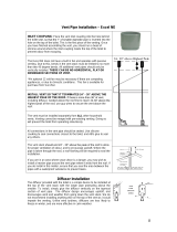
4.2.1 Using the existing ventilation port
This solution is practical as long as the port
size is 395 x 395 mm (fig. 2).
Proceed by removing the screws that fix the
port to the roof and then removing the port
itself. Scrape off all the sealing material left
around the rim of the opening (fig. 3 ref. 1)
and putty screwi holes and joints with silicon
or other products available from specialised
shops (fig. 3 ref. 2).
All waste materials
(glue, silicon, seals) must be placed in
special containers and taken to official
waste disposal centres.
4.2.2 Open new hole
Choose a central area of the roof between
two spars and trace the outline of a 395 mm
square with a felt-tip pen
(fig. 2) (fig. 4 ref. 1).
Cut the new opening in the roof carefully with
a saw: be careful not to cut any electrical
wires (fig. 4 ref. 2).
Use protective
gloves and goggles before using electrical
tools or handsaws.
Fix a reinforcement frame around the opening
(fig. 5).

SILENT 12000H
8
GB
4
1
2
4.2.3 Power lead
To power the air conditioner it is necessary to
lay a 3-pole lead (phase-neutral-earth): each
wire must have a minimum cross-section of
2.5 mm
2
. At one end the lead must be
connected to a magneto-thermal cut-out
switch inside the electrical junction box of the
vehicle; the other end must reach the aperture
on the roof, protruding from the hole on the
reinforcement frame by about 50 cm: this
additional length makes it easier to connect
up to the air conditioner (fig. 6).
Before making any
electrical connections always make sure
the power is disconnected inside the
junction box and that the wire ends are not
live.
It is compulsory for the air conditioner to be
powered via a separate line protected by a 10
A magneto-thermal cut-out switch.
To ensure good insulation under all
possible conditions electrical wiring must
be properly sheathed.
5
6

SILENT 12000H
9
GB
8
4.3 Positioning the conditioner
Before positioning the air conditioner on the
roof it is necessary to lay a sufficient amount
of slow-drying sealant around the rim of the
aperture.
Bring the air conditioner onto the roof (fig. 7
ref. 2) and, without scraping it, position it over
the 395x395 opening previously lined with
sealant. Correct alignment of the air
conditioner on the roof will provide a view -
from inside the camper - of the 4 threaded
fixing seats. The arrow in fig. 7 indicates
direction of forward drive.
The framed support
seal perimeter must be aligned with the
edge of the hole (fig 7 ref. 1).
Working from inside the camper, shift the air
conditioner until the four fixing threads are
aligned with the square opening of the hole on
the roof.
Insert, from inside the camper, the metallic
frame: align the seat of the diffuser with the
rectangular air outflow vent on the upper
section (fig. 8), then fix it in place with the four
screws (fig. 8).
Tighten the screws so that the original
thickness of the seal is reduced by a third.
Do not squeeze the seal
excessively. It must not be squeezed any
shallower than 20 mm (fig 7 ref. 3).
Excessive seal squeezing can damage the
base of the air conditioner, compromise
the airtight seal and cause loud noise
during use.
4.4 Connecting the power lead
Connect the 230 V AC power lead to the one
on the air conditioner. Observe the wire
colours:
blue wire: neutral
brown wire: phase
yellow-green wire: earth ( )
Check that the power lead is not
excessively long as it could obstruct the
intake grille.

SILENT 12000H
10
GB
4.5 Installing the diffuser
Remove the two airflow direction adjuster fins
from the diffuser.
Position the diffuser (fig. 9) momentarily and
mark the 6 hole drilling points that correspond
to the attachment points on the aluminium
duct. Drill the holes with a 3 mm bit.
Connect the panel connector (fig. 10 ref. 1)
and the temperature sensor connector (fig. 10
ref. 2) and fix the diffuser to the aluminum
duct with the 6 self-tapping screws (fig. 11
ref. 1).
Re-insert the two fins.
Note that the air conditioner starts working
3 minutes after being switched on.
5
ISTRUCTION FOR USE
5.1 Introduction
The manufacturer
cannot be held liable for damage caused
by improper use of the air conditioner.
The SILENT air conditioner consists of four
main parts:
• compressor, which circulates the coolant gas
through the system;
• condenser, which cools the coolant by
changing it from a gaseous to a liquid state.
• injector, housed in the evaporator, which
changes the coolant from a liquid to a
gaseous state;
• evaporator, which, cooled by the change of
state of the coolant, cools the air passing
through it. Air temperature is adjusted via a
thermostat and tip in atmosphere.
The SILENT provides cold air during the
summer months and hot air in winter.
If the vehicle has been left in the sun for some
time it is good practice to open windows and
doors before starting the conditioner so as to
9
2
1
10
11
1

SILENT 12000H
11
GB
release the build up of heat in the interior;
once indoor temperature matches outdoor
temperature close the windows and doors and
start the air conditioner. Subsequently, only
open doors and windows when necessary.
5.2 Preliminary checks
Before switching on the air conditioner for the
very first time:
• Check that condensate drainage holes are
unobstructed.
• Check that power voltage and frequency are
as indicated in the previous section.
• Check that air flow through relative ducts and
vents is unobstructed. To ensure maximum
efficiency always keep external ventilation
grilles clear.
5.3 Control panel (fig 12)
Fan speed key (fig. 12 ref. 1)
Thermostat adjuster knob (fig. 12 ref. 2)
On/off switch (fig. 12 ref. 3)
Menu key (fig. 12 ref. 4)
Display (fig. 12 ref. 5)
5.4 Switching on
To switch the air conditioner on
press the on/off key (fig. 12 ref. 3)
and at the same time, the display is
active.
After switching on the
conditioner there is a 3-minute pause
before the compressor is started and cold
air outflow begins.
The conditioner
features an automatic thermostat with a
minimum working temperature of 16°C
(+/- 1°C).
Below this temperature the thermostat
does not enable the compressor: this
prevents ice forming inside the unit. Fans
and the heating function remain enabled.

SILENT 12000H
12
GB
5.5 Display (fig.12 rif.5)
The display shows the temperature setting
(SET). Temperature is set via the thermostat
knob (fig. 12 ref. 2).
Press the menu key
(fig. 12 rif.4) on the display and the
ambient temperature (TA) inside the
vehicle is displayed for a few seconds.
The display then reverts to the
temperature setting.In addition to
temperature, the Display (fig. 12 ref. 5)
also shows the following:
5.6 Setting fan speed
Press the speed key
(fig. 12 rif. 1)
If pressed once the display shows the fan
speed setting: this is shown for a few seconds
before the display reverts to ambient
temperature (TA). To modify fan speed keep
pressing the key: fan speed will be adjusted
according to the following sequence
In which F11, F12 and F13 are the three fixed
speeds and AUT is automatic speed. F11
indicates slow fan speed, F12 medium speed
and F13 high speed.
If one of the three fixed speeds is set the
control panel always activates ventilation at
that same speed. If, instead, fan speed is set
to AUT, the control panel step by step (fig.
12) automatically selects the most appropriate
fan speed in consideration of the temperature
setting and the temperature in the vehicle
interior.
5.7 Thermostat (fig.12 rif.2)
Rotate the thermostat to set the desired
temperature on the display.
The control panel (fig. 12) allows
automatic control of temperature in the
vehicle interior.
If, for example, we set a temperature of
25°C the conditioner will produce cold air
as long as the temperature inside the
vehicle is higher than 25°C.
When the temperature inside the vehicle
(ambient temperature) is lower than the
setting (25°C) the conditioner activates the
incorporated heater to produce hot air.
Correct use of the thermostat is very
important.If you set a temperature much
lower than outdoor temperature (more
than 8°C lower) you run the risk of falling
ill (catching colds etc.) and energy
consumption increases.

SILENT 12000H
13
GB
5.8 Cooling mode
- When this symbol is displayed constantly the
air conditioner is generating cold air.
- When the symbol flashes, the air
conditioner is restoring gas pressures inside
its interior and will start producing cold air
after 3 minutes.
- When neither the symbol not the heating
symbol appear this means that:
a) a) ambient temperature has reached the
set temperature so the compressor is off and
only the ventilation fans are working.
b) temperature is less than 16°C and the
thermostat is set to minimum.
In this case, as long as ambient temperature
remains below the 16°C threshold, only the
fans work; the compressor is shut down.
5.9 Heating by heat pump
When this sysmbol is displayed, the air
conditioner is generating hot air through the
heat pump.
Should the air conditioner be switched off,
during the heating function, the fan will go on
running for some minutes, in order to
eliminate heat accumulated inside the air
conditioner; then it will stop by itself.
The steady symbol indicates that the
compressor is running. The flashing symbol
indicates the stand-by function, during which
the compressor is not running and is going to
be started again.
5.10 Switching off
To switch the air conditioner off press the
on/off key
(fig. 12 ref. 3).
5.11 Safety regulations
• Always use properly earthed power
sockets with differential safety switches.
• Never use the air conditioner near
flammable liquids.
• Do not use the air conditioner for
purposes other than those stated by the
manufacturer.
• Do not modify or tamper with any parts of
the air conditioner.
• Use only original spare parts.
• Maintenance and repairs must only be
carried out by specialised personnel.
• Installation must be carried out by
qualified personnel.
• Keep children/animals away from the air
conditioner unit.
• Do not insert fingers in ventilation
grilles/vents.
• Do not insert objects into ventilation
intakes.
• If the air conditioner receives any hard
knocks have it checked by specialised
personnel before using it again.
• In the event of fire never open the upper
cover of the conditioner: use homologated
fire extinguishers.
• Do not attempt to put out a fire with water.

SILENT 12000H
14
GB
6
TROUBLESHOOTING
In the majority of cases poor air conditioner
performance is caused by incorrect use as
opposed to actual malfunctions. For example:
1. The unit is too small for the volume of air you
wish to condition.
2. The vehicle is poorly insulated.
3. The doors are opened too frequently.
4. There are too many people inside the vehicle.
5. Power supply voltage is less than 230 V.
There follows a list of the most common
problems with relative cause and solution.
Before inspecting for
any other causes of poor air conditioner
performance always check:
• the power supply, which must never be
less than 205 V.
• that intake vents are unobstructed.
• that air outflow vents are open.
1) The air conditioner does not start
• check that the ON/OFF switch is positioned
to ON (fig 12 ref. 3).
• check that the socket is providing power:
check by connecting up any other appliance
or use a voltmeter..
2) The compressor does not start but the
fans are working
• ambient temperature is lower than 16°C.
• set temperature higher than ambient
temperature.
3) The condenser fan is not working
• check that the condenser fan is not structed
by foreign bodies.
4) Heating does not work
• check that set temperature is higher than
ambient temperature.
5) Air conditioner efficiency is poor
•
if the air conditioner is working inefficiently it
is necessary to clean the air filter, condenser
and evaporator using specific detergents. It is
always advisable to clean the air conditioner
when it has remained idle for along period. If,
after cleaning the heat exchangers, the unit
still fails to regain its initial efficiency check for
coolant gas loss.
7
DISPOSAL
Always contact specialised workshops when it
is necessary to dismantle and dispose of the
air conditioner.
Waste materials must not be dispersed
into the environment: always take them to
authorised waste collection centres.

SILENT 12000H
15
GB
8
MAINTENANCE
8.1 Routine maintenance
All tasks requiring removal of air
conditioner covers must – as with
installation - be carried out by expert
personnel.
Before carrying out any work on the air
conditioner it is essential that you
disconnect the 230 V power supply and
wait for all its component parts to cool
down.
• Remove the external cover and spray a
suitable detergent onto the heat
exchangers (evaporator and condenser)
and then rinse to remove impurities.
• Check that the condensate drain holes are
unobstructed.
• Check that the seals are in good condition
and there is no infiltration of water into the
vehicle.
• All traces of oxidation must be removed
and metallic parts coated with a suitable
paint.
• Check that wiring insulation is in good
condition and eliminate any traces of
moisture.
• Check that all screws are properly
tightened.
• If the vehicle is garaged for the winter
disconnect the air conditioner from the
power socket.

SILENT 12000H
16
GB
GENERAL TERMS OF WARRANTY
TELAIR guarantees its products against any construction material and/or
manufacturing faults and defects.
The right to warranty cover for new products is valid for a period of 24
months from the time of handing over to the end user, or for a maximum of
1000 operating hours, whichever limit is reached first. In all cases the
warranty period shall end no later than 26 months (28 months if delivered
outside of Europe) after ex factory delivery.
For electric and hydraulic components, pipes, belts, sealing elements,
injection nozzles, clutches, drives, the warranty term is 12 months from the
time of handing over to the end user, or a maximum of 1000 operating
hours, whichever limit is reached first. In all cases the warranty period
shall end no later than 14 months (16 months if delivered outside of
Europe) after ex factory delivery.
In any case, the costs of lubricants and consumables shall be charged.
Any transport expenses shall have to be covered by the purchaser; the same
applies to any expenses connected with inspections requested by the
customer and accepted by TELAIR.
The manufacturer’s warranty shall only be valid if:
• the customer has carried out all routine maintenance according to the
recommended schedule and has promptly visited the nearest after-sale
centre if required.
• the customer can produce a document showing the date of sale (invoice or
receipt).
Such document will have to be kept with care and be intact when produced
to the TELAIR After-Sales centre on requesting service.
In any case, the purchaser shall not be entitled to:
• terminate the contract;
• claim damages to persons or property;
• ask that the warranty be extended in the event of product defects or
malfunctioning.

SILENT 12000H
17
GB
WIRING DIAGRAM SILENT 12000H
RAM = Relay. Starter Compressor
C2 = Condens.
Starter Compressor
C3
=
Condens. 3uF, evaporating fan
C4 = Condens
. 3uF, condensing fan
C5 = Condens. Compressor On
K1 = COMPRESSOR relay
KC = HOT relay
M1 = COMPRESSOR motor
CN = Connector electrical 11 poli
MVC = Condensing fan motor
MVE = Evaporating fan motor
YC = Solenoid pump heat
PMX= HIGH PRESSURE SWITCH
ST2 = Evaporator thermo sensor
ATV = Automatic evaporating fan speed adjuster
INDEX
Digital
Thermoregulator
Pink
White
Green
Gray
Blue
Red
Brown
Pink
White
Green
Gray
Blue
Red
Brown
Blue

SILENT 12000H
18
GB
DRAWING FOR SPARE PARTS LIST SILENT 12000H

SILENT 12000H
19
GB

SILENT 12000H
20
GB
/