5
2 Mounting
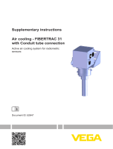
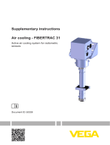
Air cooling - MINITRAC 31 • Active air cooling system for radiometric sensors
50337-EN-201120
2 Mounting
Mounting preparations
Take note of the operating instructions manuals of the corresponding
radiometric sensors and the source holder.
Warning:
During all mounting and dismounting work, the source container must
be in switch position "OFF" and secured by a lock.
Carry out all work within the shortest possible time and at the largest
possible distance. Provide suitable shielding.
Avoid risk to other persons by taking suitable measures (e.g. safety
fence, etc.).
Mountingmayonlybecarriedoutbyauthorized,qualiedpersonnel
who are monitored for radiation exposure according to local laws or
thehandlingpermit.Takenoteofthespecicationsinthehandling
permit. Also take the local conditions into account.
Caution:
The cooling system is used in areas with high temperatures. There-
fore, use temperature-resistant cable and install it in such a way that
contact with hot components is avoided.
Information:
When the sensor is ordered with cooling, the sensor and the air cool-
ing system are shipped pre-assembled.
If the air cooling system is ordered later, you have to mount it on the
sensor yourself.
Required tools:
•
Fork wrench SW13 mm (2 pieces) - for the housing cooling
•
Fork wrench SW19 mm (2 pcs.) - for the connections of the vortex
coolers
Take note of the following general mounting instructions:
•
First of all, mount the fastening bracket and the housing cooling,
and then the sensor
•
The small lid of the instrument housing must point to the front after
mounting the fastening bracket (x)
•
The sensor together with the air cooling system is very heavy. Use
a suitable lifting device for mounting, e.g. a hoisting sling
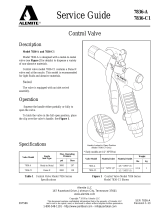
1. Place the isolating sleeves (4) between the housing cooling (5)
and the fastening bracket (1).
Operating instructions
General mounting
instructions
Mount the fastening
bracket