Page is loading ...

ACH550
Installation, Operation and Maintenance Manual (I, O & M)
ACH550-UH HVAC Drives (1
…550 HP)
ACH550-BCR/BDR/VCR/VDR E-Clipse Bypass Drives (1
…400 HP)
ACH550-PCR/PDR Packaged Drives with Disconnect (1
…550 HP)

2 ACH550 Installation, Operation and Maintenance Manual
Safety
Safety
Use of warnings and notes
There are two types of safety instructions throughout this manual:
• Notes draw attention to a particular condition or fact, or give information on a
subject.
• Warnings caution you about conditions which can result in serious injury or death
and/or damage to the equipment. They also tell you how to avoid the danger. The
warning symbols are used as follows:
Electricity warning warns of hazards
from electricity which can cause
physical injury and/or damage to the
equipment.
• WARNING! The ACH550 adjustable speed
AC drive should ONLY be installed by a
qualified electrician.
• WARNING! Even when the motor is
stopped, dangerous voltage is present at the
power circuit terminals U1, V1, W1 (L1, L2,
L3) and U2, V2, W2 (T1, T2 T3) and,
depending on the frame size, UDC+ and
UDC-, or BRK+ and BRK-.
• WARNING! Dangerous voltage is present
when input power is connected. After
disconnecting the supply, wait at least 5
minutes (to let the intermediate circuit
capacitors discharge) before removing the
cover.
• WARNING! Even when power is switched
off from the input terminals of the ACH550,
there may be dangerous voltage (from
external sources) on the terminals of the
relay outputs.
• WARNING! When the control terminals of
two or more drives are connected in parallel,
the auxiliary voltage for these control
connections must be taken from a single
source which can either be one of the drives
or an external supply.
• WARNING! Disconnect the internal EMC
filter when installing the drive on an IT
system (an ungrounded power system or a
high-resistance-grounded [over 30 ohm]
power system).
• WARNING! Do not attempt to install or
remove EM1, EM3, F1 or F2 screws while
power is applied to the drive’s input
terminals.
General warning warns about
conditions, other than those caused
by electricity, which can result in
physical injury and/or damage to the
equipment.
• WARNING! Do not control the motor with
the disconnecting device (disconnecting
means); instead, use the control panel keys
or commands via the I/O board of the drive.
The maximum allowed number of charging
cycles of the DC capacitors (i.e. power-ups
by applying power) is five in ten minutes.
• WARNING! Never attempt to repair a
malfunctioning ACH550; contact the factory
or your local Authorized Service Center for
repair or replacement.
• WARNING! The ACH550 will start up
automatically after an input voltage
interruption if the external run command is
on.
• WARNING! The heat sink may reach a high
temperature.
Note: For more technical information, contact
the factory or your local ABB representative.

ACH550 Installation, Operation and Maintenance Manual 3
ACH550-UH
Contents
This manual is the Operation and Maintenance Manual for the ACH550 Drives.
Complete technical details and programming information are available in the
ACH550 User’s Manual, publication number 3AUA0000081823.
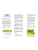
1. To determine the type of your drive, refer to its construction code on either:
• Serial number label attached on upper part of
the chokeplate between the mounting holes.
• Type code label attached on the heat sink – on
the side of the enclosure.
2. According to the construction code, proceed to your drive’s installation, operation,
diagnostics and maintenance information:
• UH – Below.
• VCR, VDR, BCR, BDR (E-Clipse Bypass) – page 39.
• PCR, PDR (Packaged Drives with Disconnect) – page 79.
ACH550-UH
Installation
Study these installation instructions carefully before proceeding. Failure to observe
the warnings and instructions may cause a malfunction or personal hazard.
WARNING! Before you begin read Safety on page 2.
Note: Keep a minimum of 50 mm (2") of free space on each side and 200 mm (8") of
free space above and below all units from non-heat producing sources. Double
these distances from heat producing sources.
S/N
ACH550-UH-059A-2
2030700001
SW:
V.2.06B
2030700001
Input
Voltage (U1)
Current (I1n)
3 PH 48…63 Hz
200…240 Vac
59.4 A
1 PH 4…63 Hz
200…240 Vac
59.4 A
Output
Voltage (U2)
Current (I2n)
3 PH 0…500 Hz
0…U1 Vac
59.4 A
3 PH 0…500 Hz
0…U1 Vac
28 A
ACH550-UH-059A-2
Power (Pn)
Mfg. Date: 01-December-2005
Org. Firmware: V.2.06B
ABB Inc.
Made in USA of foreign parts
10 HP20 HP
kAIC
S/N
2030700001
Construction
code

4 ACH550 Installation, Operation and Maintenance Manual
ACH550-UH
1. Prepare for installation
Lifting R1…R6
Lift the drive only by the metal chassis.
Lifting R7…R8
WARNING! Handle and ship floor mounted enclosures only in the upright position.
These units are not designed to be laid on their backs.
1. Use a pallet truck to move the transport package/enclosure to the installation site.
2. Remove the cabinet side panels for access to the cabinet/pallet mounting bolts.
(6 torx screws hold each cabinet side panel in place. Leave the side panels off until
later.)
3. Remove the 4 bolts that secure the cabinet to the shipping pallet.
WARNING! Use the lifting lugs/bars at the top of the unit to lift R7/R8 drives.
4. Use a hoist to lift the drive. (Do not place drive in final position until mounting site is
prepared.)
Unpack the drive
1. Unpack the drive.
2. Check for any damage and notify the shipper immediately if damaged components
are found.
3. Check the contents against the order and the shipping label to verify that all parts
have been received.
Tools required
To install the ACH550 you need the following:
• Screwdrivers (as appropriate for the mounting hardware used)
• Wire stripper
• Tape measure
•Drill
• Frame sizes R5…R8 with UL type 12 enclosure: Punch for conduit mounting
holes
• Frame sizes R7/R8: pallet truck and hoist
• For installations involving frame size R6…R8: The appropriate crimping tool for
power cable lugs.

ACH550 Installation, Operation and Maintenance Manual 5
ACH550-UH
• Mounting hardware: screws or nuts and bolts, four each. The type of hardware
depends on the mounting surface and the frame size:
• For installations involving frame size R7…R8: Hoist.
WARNING! Before installing the ACH550, ensure the input power supply to the drive
is off.
WARNING! Metal shavings or debris in the enclosure can damage electrical
equipment and create a hazardous condition. Where parts, such as conduit plates
require cutting or drilling, first remove the part. If that is not practical, cover nearby
electrical components to protect them from all shavings or debris.
Flange Mounting Instructions
2. Prepare the mounting location
1. Mark the position of the mounting holes.
Note: Frame sizes R3 and R4 have four holes along the top. Use only two. If
possible, use the two outside holes (to allow room to remove the fan for
maintenance).
Note: ACH400 drives can be replaced using the original mounting holes. For R1 and
R2 frame sizes, the mounting holes are identical. For R3 and R4 frame sizes, the
inside mounting holes on the top of ACH550 drives match ACH400 mounts.
Frame Size Mounting Hardware Note
R1…R4 M5 #10
R5 M6 1/4 in
R6 M8 5/16 in
R7…R8 M10
7/16 Secures free standing cabinets if required.
Frame size
IP21 / UL type 1 IP54 / UL type 12
Kit Code (English) Kit Code (English)
R1 FMK-A-R1 100000982 FMK-B-R1 100000990
R2 FMK-A-R2 100000984 FMK-B-R2 100000992
R3 FMK-A-R3 100000986 FMK-B-R3 100000994
R4 FMK-A-R4 100000988 FMK-B-R4 100000996
R5 AC8-FLNGMT-R5 ACS800-PNTG01U-EN - -
R6 AC8-FLNGMT-R6 - -

6 ACH550 Installation, Operation and Maintenance Manual
ACH550-UH
Note: Frame sizes R7 and R8 have mounting holes inside the enclosure base.
Where it is not possible to use either mounting hole at the back of the base, use an
L-bracket at the top of the enclosure to secure the cabinet to a wall or to the back of
another enclosure. Bolt the L-bracket to the enclosure using the lifting lug bolt hole
on the top of the enclosure.
2. Drill holes of appropriate size in the mounting location.
3. Remove front cover
R1…R6, UL type 1
1. Remove the control panel, if attached.
2. Loosen the captive screw at the top.
3. Pull near the top to remove the cover.
R1…R6, UL type 12
1. If hood is present: Remove screws (2) holding the hood in place.
2. If hood is present: Slide hood up and off of the cover.
3. Loosen the captive screws around the edge of the cover.
4. Remove the cover.
R7…R8, Cabinet Door
1. To open the cabinet door, loosen the quarter-turn screws that hold the cabinet door
closed.
R7…R8, Side Panels
The side panels were removed to take the cabinet off the pallet. Installation access is
easier if these panels are kept off throughout the installation.
4. Mount the drive
R1…R6, UL type 1
1. Position the ACH550 onto the mounting screws
or bolts and securely tighten in all four corners.
Note: Use mounting hardware that permits fan
replacement without removal.
Note: Lift the ACH550 by its metal chassis.
2. Non-English speaking locations: Add a warning
sticker in the appropriate language over the existing warning on the top of the
module.
IP2002
1
2

ACH550 Installation, Operation and Maintenance Manual 7
ACH550-UH
R1…R6, UL type 12
For the UL type 12 enclosures, rubber plugs are required in the holes provided for
access to the drive mounting slots.
1. As required for access, remove the rubber plugs.
Push plugs out from the back of the drive.
2. R5 & R6: Align the sheet metal hood (not shown)
in front of the drive’s top mounting holes. (Attach
as part of next step.)
3. Position the ACH550 onto the mounting screws
or bolts and securely tighten in all four corners.
Note: Lift the ACH550 by its metal chassis
(frame size R6 by the lifting holes on both sides
at the top).
4. Re-install the rubber plugs.
5. Non-English speaking locations: Add a warning sticker in the appropriate language
over the existing warning on the top of the module.
R7…R8
1. Use a hoist to move the cabinet into position.
Note: If the cabinet location does not provide access to the cabinet sides, be sure to
re-mount side panels before positioning cabinet.
2. Install and tighten mounting bolts.
5. Install wiring
WARNING! Ensure the motor is compatible for use with the ACH550. The ACH550
must be installed by a competent person. If in doubt, contact your local ABB sales or
service office.
Conduit kit
Wiring R1…R6 drives with the UL type 1 Enclosure requires a conduit kit with the
following items:
• conduit box
•screws
• cover
The kit is included with UL type 1 Enclosures.
2
1, 3
FM

8 ACH550 Installation, Operation and Maintenance Manual
ACH550-UH
Connection diagrams
The following diagrams show:
• The terminal layout for frame size R3, which, in general, applies to frame sizes
R1
…R6, except for the R5/R6 power and ground terminals.
• The R5/R6 power and ground terminals.
• The terminal layout for R7/R8.
WARNING! To avoid danger, or damage to the drive, on IT systems and corner
grounded TN systems, see section Disconnecting the internal EMC filter on
page 10.
Panel Connector
Power LED (Green)
Fault LED (Red)
Optional Module 1
X1 – Communications
Optional Module 2
GND
Power Output to Motor
Power Input
EM1
X1 – Analog Inputs and Outputs
X1 – Digital Inputs
X1 – Relay Outputs
(and 10 V Ref. Voltage Output)
(and 24 V Aux. Voltage Output)
EM3
PE
(U1, V1, W1)
(U2, V2, W2)
X0003
(RS485)
R5/R6 differ.
See next page.
Frame Sizes
R1…R4 (Diagram shows the R3 frame.)
J2 – DIP Switches
J2
ON
off position on position
for RS485 Termination
J2
ON
Terminals Not Used
J1 – DIP Switches for Analog Inputs
AI1: (in Voltage Position)
AI2: (in Current Position)
ON
ON
The switch is one of two types:
Alternate
Original
Illustration of available switch
positions; not default settings
Illustration of available switch
positions; not default settings

ACH550 Installation, Operation and Maintenance Manual 9
ACH550-UH
WARNING! To avoid danger, or damage to the drive, on IT systems and corner
grounded TN systems, see section Disconnecting the internal EMC filter on
page 10.
GND
Power Input
PE
(U1, V1, W1)
X0011
F1
F2
Power Input
PE
(U1, V1, W1)
F1
F2
X0013
Power Output to Motor
(U2, V2, W2)
R6
GND
GND
Power Output to Motor
(U2, V2, W2)
Terminals Not Used
Terminals Not Used
R5

10 ACH550 Installation, Operation and Maintenance Manual
ACH550-UH
Disconnecting the internal EMC filter
On certain types of systems, you must disconnect the internal EMC filter, otherwise
the system will be connected to ground potential through the EMC filter capacitors,
which might cause danger, or damage the drive.
Note: When the internal EMC filter is disconnected, the drive is not EMC compatible.
The following table shows the installation rules for the EMC filter screws in order to
connect or disconnect the filter, depending on the system type and the frame size.
For more information on the different system types, see Floating networks on page
12 and Unsymmetrically grounded networks on page 11.
The locations of screws EM1 and EM3 are shown in the diagram on page 8. The
locations of screws F1 and F2 are shown in the diagram on page 9.
Frame
sizes
Screw
Symmetrically
grounded TN systems
(TN-S systems)
Corner grounded
TN systems
IT systems (ungrounded
or high-resistance-
grounded [> 30 ohm])
R1…R3
EM1 x x
EM3 x
R4
EM1 x x –
EM3 x ––
R5…R6
F1 x x –
F2 x x –
x = Install the screw. (EMC filter will be connected.)
= Replace the screw with the provided polyamide screw. (EMC filter will be disconnected.)
–
= Remove the screw. (EMC filter will be disconnected.)
EM1 and EM3 screws are M4 x 12
F1 and F2 screws are M4 x 16
Ground Lug
Bar
ACH550
R7 (R8 Similar)
Motor
Terminals
Input Power
Terminals
Control Wires
(X1)
Terminal Strip
Only on
ACH550-UH

ACH550 Installation, Operation and Maintenance Manual 11
ACH550-UH
Ground connections
For personnel safety, proper operation and to reduce electromagnetic emission/pick-
up, the drive and the motor must be grounded at the installation site.
• Conductors must be adequately sized as required by safety regulations.
• Power cable shields must be connected to the drive PE terminal in order to meet
safety regulations.
• Power cable shields are suitable for use as equipment grounding conductors only
when the shield conductors are adequately sized as required by safety
regulations.
• In multiple drive installations, do not connect drive terminals in series.
Unsymmetrically grounded networks
WARNING! Do not attempt to install or remove EM1 or EM3 screws while power is
applied to the drive’s input terminals.
Unsymmetrically grounded networks are defined in the following table. In such
networks, the internal connection provided by the EM3 screw (on frame sizes
R1…R4 only) must be disconnected by removing EM3. If the grounding
configuration of the network is unknown, remove EM3.
Note: ACH550-UH drives are shipped with the screw removed (but included in the
conduit box).
Unsymmetrically Grounded Networks – EM3 Must Be Out
Grounded at the
corner of the
delta
Grounded at the
mid point of a
delta leg
Single phase,
grounded at an
end point
Three phase
“Variac” without
solidly grounded
neutral
L1
L2
L3
L1
L2
L3
L1
N
L1
L1
L2
L2
L3
L3

12 ACH550 Installation, Operation and Maintenance Manual
ACH550-UH
EM3 (an M4x16 screw) makes an internal ground connection
that reduces electro-magnetic emission. Where EMC (electro-
magnetic compatibility) is a concern, and the network is
symmetrically grounded, EM3 may be installed. For
reference, the diagram at right illustrates a symmetrically
grounded network.
Floating networks
WARNING! Do not attempt to install or remove EM1, EM3, F1 or F2 screws while
power is applied to the drive’s input terminals.
For floating networks (also known as IT, ungrounded, or impedance/resistance
grounded networks):
• Disconnect the ground connection to the internal RFI filters:
– Frame sizes R1…R4: Remove the EM1 screw (unit is shipped with EM3
removed, see Connection diagrams on page 8).
– Frame sizes R5…R6: Remove both the F1 and F2 screws (see page 9).
• Where EMC requirements exist, check for excessive emission propagated to
neighboring low voltage networks. In some cases, the natural suppression in
transformers and cables is sufficient. If in doubt, use a supply transformer with
static screening between the primary and secondary windings.
• Do NOT install an external RFI/EMC filter. Using an RFI filter grounds the input
power through the filter capacitors, which could be dangerous and could damage
the unit.
Checking motor and motor cable insulation
WARNING! Check the motor and motor cable insulation before connecting the drive
to input power. For this test, make sure that motor cables are NOT connected to the
drive.
1. Complete motor cable connections to the motor, but NOT to the drive output
terminals (U2, V2, W2).
2. At the drive end of the motor cable, measure the insulation
resistance between each motor cable phase and Protective
Earth (PE): Apply a voltage of 1 kV DC and verify that
resistance is greater than 1 Mohm.
L1
L2
L3
PE
M
ohm

ACH550 Installation, Operation and Maintenance Manual 13
ACH550-UH
R1…R6, wiring UL type 1 enclosure
1. Open the appropriate knockouts in the
conduit box. (See Conduit kit on page 7.)
2. Install thin-wall conduit clamps (not supplied).
3. Install conduit box.
4. Connect conduit runs for input power, motor
and control cables to the box.
5. Route input power and motor wiring through
separate conduits.
6. Strip wires.
7. Connect power, motor, and ground wires to
the drive terminals.
Note: For R5 frame size, the minimum power cable size is 25 mm
2
(4 AWG). For R6
frame size, refer to Power terminal considerations – R6 Frame size on page 16.
8. Route the control cables through the conduit
(not the same conduit as either input power or
motor wiring).
9. Use available secure points and tie strap
landings to permanently secure control wiring
at a minimum distance of 6 mm (1/4") from
power wiring.
10. Strip the control cable sheathing and twist the
copper screen into a pig-tail.
11. Connect the ground screen pig-tail for digital
and analog I/O cables at X1-1. (Ground only
at drive end.)
12. Connect the ground screen pig-tail for RS485
cables at X1-28 or X1-32. (Ground only at
drive end.)
13. Strip and connect the individual control wires to the drive terminals.
14. Install the conduit box cover (1 screw).
2
X0007
3
X0005
4
IP2004
7
7
5
10
8
IP2005
12

14 ACH550 Installation, Operation and Maintenance Manual
ACH550-UH
R1…R6, wiring UL type 12 enclosure
1. Step depends on Frame Size:
• Frame Sizes R1…R4: Remove and discard the
cable seals where conduit will be installed. (The
cable seals are cone-shaped, rubber seals on
the bottom of the drive.)
• Frame Sizes R4 and R5: Use punch to create
holes for conduit connections as needed.
2. For each conduit run (input power, motor and
control wiring must be separate), install liquid tight
conduit connectors (not supplied).
3. Route the power wiring through conduit.
4. Route the motor wiring through conduit (not the
same conduit as input power wiring run).
5. Strip the wires.
6. Connect the power, motor, and ground wires to
the drive terminals.
Note: For R5 frame size, the minimum power cable size is 25 mm
2
(4 AWG). For R6
frame size, refer to Power terminal considerations – R6 Frame size on page 16.
7. Route the control cables through the conduit (not
the same conduit as either input power or motor
wiring runs).
8. Use available secure points and tie strap landings to
permanently secure control wiring at a minimum
distance of 6 mm (1/4") from power wiring.
9. Strip the control cable sheathing and twist the
copper screen into a pig-tail.
10. Connect the ground screen pig-tail for digital and
analog I/O cables at X1-1. (Ground only at drive
end.)
11. Connect the ground screen pig-tail for RS485 cables
at X1-28 or X1-32. (Ground only at drive end.)
12. Strip and connect the individual control wires to the drive
terminals.
13. Install the conduit box cover (1 screw).
IP50131
R1…R4
IP5023
1
R5, R6
2
IP5006
3
IP5007
6
4
7
IP5008
9…11

ACH550 Installation, Operation and Maintenance Manual 15
ACH550-UH
R7…R8, wiring (both enclosure types)
The figures show connections in the R7 cabinet, the R8 cabinet is similar.
1. Remove the conduit connection plate from the top of the left bay.
2. Route the input power, motor and control
cables to the top of the cabinet. Each cable
type (input power, motor, and control) must
be in separate conduit.
3. Use punch to create holes for conduit
connections as needed.
4. UL type 12 Enclosure: For each conduit
run (input power, motor and control wiring
must be separate), install liquid tight
conduit connectors (not supplied).
5. Connect input power and motor cables to
the bus terminals.
6. Connect grounds to ground bar.
7. Use available secure points and tie strap
landings to permanently secure control
wiring at a minimum distance of 6 mm
(1/4") from power wiring.
8. Strip the control cable sheathing and twist
the copper screen into a pig-tail.
9. Connect the ground screen pig-tail for
digital and analog I/O cables at X1-1.
(Ground only at drive end.)
10. Connect the ground screen pig-tail for
RS485 cables at X1-28 or X1-32. (Ground
only at drive end.)
11. Strip and connect the individual control wires to the drive terminals.
BP0054
Input Power
Gnd
Cable
Terminal Strip
Only on
ACH550-UH
BP0054
Motor
Gnd
Cable

16 ACH550 Installation, Operation and Maintenance Manual
ACH550-UH
Drive’s power connection terminals
The following table provides specifications for the drive’s power connection terminals.
1. Do not use aluminum cable with frame sizes R1…R4.
2. See the following section for smaller wire sizes on frame size R6.
Power terminal considerations – R6 Frame size
WARNING! For R6 power terminals, if compression lugs are supplied, they can only
be used for wire sizes that are 95 mm
2
(3/0 AWG) or larger. Smaller wires will loosen
and may damage the drive, and require ring lugs as described below.
On the R6 frame size, if the cable size used is less than 95 mm
2
(3/0 AWG) or if no
compression lugs are supplied, use ring lugs.
Drive’s control connection terminals
The following table provides specifications for the drive’s control terminals
Control terminal descriptions
The following full-page diagram provides a general description of the control
terminals on the drive.
Note: Terminals 3, 6, and 9 are at the same potential.
Note: For safety reasons the fault relay signals a “fault” when the ACH550 is
powered down.
Frame
Size
U1, V1, W1
U2, V2, W2
BRK+
, UDC+ Terminals
Earthing PE Terminal
Min. Wire Size Max. Wire Size Torque Max. Wire Size Torque
mm
2
AWG mm
2
AWG Nm lb-ft mm
2
AWG Nm lb-ft
R1
Note 1
0.75 18 16 61.311661.31
R2
Note 1
0.75 18 16 61.311661.31
R3
Note 1
2.5 14 25 32.722532.72
R4
Note 1
10 8501/0 5.6 4501/0 5.6 4
R5 16 6702/0 15 11 70 2/0 15 11
R6 95
Note 2
3/0 185 350 MCM 40 30 185 350 MCM 40 30
R7 16
6185350 MCM 40 30 Attach appropriate ring lugs to
ground wires and mount with,
up to five 13/32 bolts.
R8 16 62x2402x500 MCM 57 42
Frame Size
Control
Maximum Wire Size Torque
mm
2
AWG Nm lb-ft
All 1.5
16 0.4 0.3

ACH550 Installation, Operation and Maintenance Manual 17
ACH550-UH
1 Digital input impedance 1.5 k. Maximum voltage for digital inputs is 30 V.
2 Default values depend on the macro used. Values specified are for the HVAC default macro.
X1 Drive Control Terminal Description
1 SCR Terminal for signal cable screen. (Connected internally to chassis ground.)
2 AI1 Analog input channel 1, programmable. Default
2
= external reference. Resolution
0.1%, accuracy ±1%.
J1:AI1 OFF: 0(2)…10 V (R
i
=312k)
J1:AI1 ON: 0(4)…20 mA (R
i
=100)
3 AGND Analog input circuit common (connected internally to chassis gnd. through 1 M).
4 +10 V Potentiometer reference source: 10 V ±2%, max. 10 mA (1k <
R < 10k).
5 AI2 Analog input channel 2, programmable. Default
2
= PID feedback. Resolution 0.1%,
accuracy ±1%.
J1:AI2 OFF: 0(2)…10 V (R
i
=312k)
J1:AI2 ON: 0(4)…20 mA (R
i
=100)
6 AGND Analog input circuit common (connected internally to chassis gnd. through 1 M).
7 AO1 Analog output, programmable. Default
2
= frequency. 0…20 mA (load < 500 ).
Accuracy ±3% full scale.
8 AO2 Analog output, programmable. Default
2
= current. 0…20 mA (load < 500 ).
Accuracy ±3% full scale.
9 AGND Analog output circuit common (connected internally to chassis gnd. through 1 M).
10 +24V Auxiliary voltage output 24 VDC / 250 mA (reference to GND), short circuit
protected.
11 GND Auxiliary voltage output common (connected internally as floating).
12 DCOM Digital input common. To activate a digital input, there must be 10 V
(or -10 V) between that input and DCOM. The 24 V may be provided by the
ACH550 (X1-10) or by an external 12…24 V source of either polarity.
13 DI1 Digital input 1, programmable. Default
2
= start/stop.
14 DI2 Digital input 2, programmable. Default
2
= not configured.
15 DI3 Digital input 3, programmable. Default
2
= constant (preset) speed.
16 DI4 Digital input 4, programmable. Default
2
= safety interlock.
17 DI5 Digital input 5, programmable. Default
2
= not configured.
18 DI6 Digital input 6, programmable. Default
2
= not configured.
19 RO1C Relay output 1, programmable. Default
2
= Ready
Maximum: 250 VAC / 30 VDC, 2 A
Minimum: 500 mW (12 V, 10 mA)
20 RO1A
21 RO1B
22 RO2C Relay output 2, programmable. Default
2
= Running
Maximum: 250 VAC / 30 VDC, 2 A
Minimum: 500 mW (12 V, 10 mA)
23 RO2A
24 RO2B
25 RO3C Relay output 3, programmable. Default
2
= Fault (-1)
Maximum: 250 VAC / 30 VDC, 2 A
Minimum: 500 mW (12 V, 10 mA)
26 RO3A
27 RO3B
Analog I/O
ON
ON
12
or, for OFF
ON
12
for ON
ON
ON
ON
12
or, for OFF
ON
12
for ON
ON
Digital Inputs
1
Relay Outputs

18 ACH550 Installation, Operation and Maintenance Manual
ACH550-UH
You can wire the digital input terminals in either a PNP or NPN configuration.
Serial communications
Terminals 28
…32 provide RS485 serial communication connections used to control
or monitor the drive from a fieldbus controller.
6. Check installation
Before applying power, perform the following checks.
7. Re-install cover
Check
Installation environment conforms to the drive’s specifications for ambient conditions.
The drive is mounted securely.
Space around the drive meets the drive’s specifications for cooling.
The motor and driven equipment are ready for start.
For floating networks (R1…R6): The internal RFI filter is disconnected (screws EM1 & EM3 or
F1 & F2).
The drive is properly grounded.
The input power voltage matches the drive nominal input voltage range.
The input power connections at U1, V1, and W1 are connected and tightened as specified.
The input power branch circuit protection is installed.
The motor connections at U2, V2, and W2 are connected and tightened as specified.
The input power, motor and control wiring are routed through separate conduit runs.
NO power factor compensation capacitors are in the motor cable.
The control connections are connected and tightened as specified.
NO tools or foreign objects (such as drill shavings) are inside the drive.
NO alternate power source for the motor (such as a bypass connection) is connected – no
voltage is applied to the output of the drive.
NPN connection (sink)PNP connection (source)
10 +24V
11 GND
12 DCOM
13 DI1
14 DI2
15 DI3
16 DI4
17 DI5
18 DI6
10 +24V
11 GND
12 DCOM
13 DI1
14 DI2
15 DI3
16 DI4
17 DI5
18 DI6
X1
X1

ACH550 Installation, Operation and Maintenance Manual 19
ACH550-UH
8. Apply power
Always re-install the covers before turning power on.
WARNING! The ACH550 will start up automatically at power up, if the external run
command is on.
Apply input power. When power is applied to the ACH550, the green LED comes on.
Note: Before increasing motor speed, check that the motor is running in the desired
direction. To change rotation direction, switch motor leads as shown below.
9. Before Start-up
The ACH550 has default parameter settings that are sufficient for many situations.
However, review the following situations. Perform the associated procedures as
appropriate.
Spin motor
When first installed and started the control panel displays a welcome screen with the
following options.
• Press Exit to commission the drive as described in section Start-up by changing
the parameters individually on page 23.
• Press Enter to move to the following options:
– Select “Commission Drive” to commission the drive as described in section
Start-Up by Start-up by using the Start-Up Assistant on page 23.
– Select “Spin Motor” to operate the motor prior to commissioning. This option
U1 V1 W1 U2 V2 W2
L1
L2
L3
Motor
Drive
Input
FM
U1 V1 W1 U2 V2 W2
L1
L2
L3
Motor
Drive
Input
To change rotation direction,
switch motor leads
GND
GND
GND
GND

20 ACH550 Installation, Operation and Maintenance Manual
ACH550-UH
operates the motor without any commissioning, except entry of the motor data
as described below. Spin Motor is useful, for example, to operate ventilation
fans prior to commissioning.
Note: When using Spin Motor, the motor speed is limited to the range 1/3…2/3 of
maximum speed. Also, no interlocks are activated. Finally, once the drive is
commissioned, the welcome screen and this option no longer appear.
Motor data
The motor data on the ratings plate may differ from the defaults in the ACH550. The
drive provides more precise control and better thermal protection if you enter the
rating plate data.
1. Gather the following from the motor ratings plate:
•Voltage
• Nominal motor current
• Nominal frequency
• Nominal speed
• Nominal power
2. Edit parameters 9905…9909 to the correct values.
• Assistant Control Panel: The Start-Up Assistant walks you through this data entry.
• Basic Control Panel: Refer to ACH550 User’s Manual, for parameter editing
instructions.
Fault and alarm adjustments
The ACH550 can detect a wide variety of potential system problems. For example,
initial system operation may generate faults or alarms that indicate set-up problems.
1. Faults and alarms are reported on the control panel with a number. Note the number
reported.
2. Review the description provided for the reported fault/alarm:
• Use the fault and alarm listings on pages 24 and 29 respectively, or
• Press the help key (Assistant Control Panel only) while fault or alarm is displayed.
3. Adjust the system or parameters as appropriate.
/