Page is loading ...

User Guide
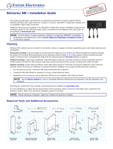
Retractor SM
Architectural Connectivity
TeamWork “Show Me” Cable Retraction Modules
68-2663-01 Rev. A
04 15
SMP 351 User Guide

Safety Instructions • English
WARNING: This symbol, , when used on the product, is intended to
alert the user of the presence of uninsulated dangerous voltage within the
product’s enclosure that may present a risk of electric shock.
ATTENTION: This symbol, , when used on the product, is intended
to alert the user of important operating and maintenance (servicing)
instructions in the literature provided with the equipment.
For information on safety guidelines, regulatory compliances, EMI/EMF
compatibility, accessibility, and related topics, see the Extron Safety and
Regulatory Compliance Guide, part number 68-290-01, on the Extron website,
www.extron.com.
Instructions de sécurité • Français
AVERTISSEMENT : Ce pictogramme, , lorsqu’il est utilisé sur le
produit, signale à l’utilisateur la présence à l’intérieur du boîtier du produit
d’une tension électrique dangereuse susceptible de provoquer un choc
électrique.
ATTENTION : Ce pictogramme, , lorsqu’il est utilisé sur le produit,
signale à l’utilisateur des instructions d’utilisation ou de maintenance
importantes qui se trouvent dans la documentation fournie avec le
matériel.
Pour en savoir plus sur les règles de sécurité, la conformité à la réglementation,
la compatibilité EMI/EMF, l’accessibilité, et autres sujets connexes, lisez les
informations de sécurité et de conformité Extron, réf. 68-290-01, sur le site
Extron, www.extron.com.
Sicherheitsanweisungen • Deutsch
WARNUNG: Dieses Symbol auf dem Produkt soll den Benutzer
darauf aufmerksam machen, dass im Inneren des Gehäuses dieses
Produktes gefährliche Spannungen herrschen, die nicht isoliert sind
und die einen elektrischen Schlag verursachen können.
VORSICHT: Dieses Symbol auf dem Produkt soll dem Benutzer in der
im Lieferumfang enthaltenen Dokumentation besonders wichtige Hinweise
zur Bedienung und Wartung (Instandhaltung) geben.
Weitere Informationen über die Sicherheitsrichtlinien, Produkthandhabung,
EMI/EMF-Kompatibilität, Zugänglichkeit und verwandte Themen finden Sie in
den Extron-Richtlinien für Sicherheit und Handhabung (Artikelnummer
68-290-01) auf der Extron-Website, www.extron.com.
Instrucciones de seguridad • Español
ADVERTENCIA: Este símbolo, , cuando se utiliza en el producto,
avisa al usuario de la presencia de voltaje peligroso sin aislar dentro del
producto, lo que puede representar un riesgo de descarga eléctrica.
ATENCIÓN: Este símbolo, , cuando se utiliza en el producto, avisa
al usuario de la presencia de importantes instrucciones de uso y
mantenimiento recogidas en la documentación proporcionada con el
equipo.
Para obtener información sobre directrices de seguridad, cumplimiento
de normativas, compatibilidad electromagnética, accesibilidad y temas
relacionados, consulte la Guía de cumplimiento de normativas y seguridad de
Extron, referencia 68-290-01, en el sitio Web de Extron, www.extron.com.
Инструкция по технике безопасности • Русский
ПРЕДУПРЕЖДЕНИЕ: Данный символ, , если указан
на продукте, предупреждает пользователя о наличии
неизолированного опасного напряжения внутри корпуса
продукта, которое может привести к поражению
электрическим током.
ВНИМАНИЕ: Данный символ, , если указан на продукте,
предупреждает пользователя о наличии важных инструкций
по эксплуатации и обслуживанию в руководстве,
прилагаемом к данному оборудованию.
Для получения информации о правилах техники безопасности,
соблюдении нормативных требований, электромагнитной
совместимости (ЭМП/ЭДС), возможности доступа и других
вопросах см. руководство по безопасности и соблюдению
нормативных требований Extron на сайте Extron: www.extron.com,
номер по каталогу - 68-290-01.
安全说明 • 简体中文
警告: 产品上的这个标志意在警告用户该产品机壳内有暴露的危险 电压,
有触电危险。
注意: 产品上的这个标志意在提示用户设备随附的用户手册中有
重要的操作和维护(维修)说明。
关于我们产品的安全指南、遵循的规范、EMI/EMF 的兼容性、无障碍
使用的特性等相关内容,敬请访问 Extron 网站 www.extron.com,参见
Extron 安全规范指南,产品编号 68-290-01。
安全記事 • 繁體中文
警告: 若產品上使用此符號,是為了提醒使用者,產品機殼內存在著
可能會導致觸電之風險的未絕緣危險電壓。
注意 若產品上使用此符號,是為了提醒使用者,設備隨附的用戶手冊中有重
要的操作和維護(維修)説明。
有關安全性指導方針、法規遵守、EMI/EMF 相容性、存取範圍和相關主題的詳
細資訊,請瀏覽 Extron 網站:www.extron.com,然後參閱《Extron 安全性與
法規遵守手冊》,準則編號 68-290-01。
安全上のご注意 • 日本語
警告: この記号 が製品上に表示されている場合は、筐体内に絶縁されて
いない高電圧が流れ、感電の危険があることを示しています。
注意: この記号 が製品上に表示されている場合は、本機の取扱説明書
に 記 載さ れている重 要 な 操 作と保 守( 整 備 )の 指 示についてユーザーの 注
意を喚起するものです。
安全上のご注意、法規厳守、EMI/EMF適合性、その他の関連項目に
つ い て は 、エ ク スト ロ ン の ウ ェ ブ サ イト www.extron.com よ り 『 Extron Safety
and Regulatory Compliance Guide』 ( P/N 68-290-01) をご覧ください。
안전 지침 • 한국어
경고: 이 기호 가 제품에 사용될 경우, 제품의 인클로저 내에 있는
접지되지 않은 위험한 전류로 인해 사용자가 감전될 위험이 있음을
경고합니다.
주의: 이 기호 가 제품에 사용될 경우, 장비와 함께 제공된 책자에 나와
있는 주요 운영 및 유지보수(정비) 지침을 경고합니다.
안전 가이드라인, 규제 준수, EMI/EMF 호환성, 접근성, 그리고 관련 항목에
대한 자세한 내용은 Extron 웹 사이트(www.extron.com)의 Extron 안전 및
규제 준수 안내서, 68-290-01 조항을 참조하십시오.
Safety Instructions
Safety Instructions and Notices

Conventions Used in this Guide
Notifications
The following notifications are used in this guide:
DANGER:
• Will result in serious injury or death.
• Entraînera des blessures graves ou la mort.
CAUTION: Risk of minor personal injury.
ATTENTION : Risque de blessuremineure.
ATTENTION:
• Risk of property damage.
• Risque de dommages matériels.
NOTE: A note draws attention to important information.
Specifications Availability
Product specifications are available on the Extron website, www.extron.com.
Extron Glossary of Terms
A glossary of terms is available at http://www.extron.com/technology/glossary.aspx.

NOTE: For information on safety guidelines, regulatory compliances, EMI/EMF compatibility, accessibility,
and related topics, see the “Extron Safety and Regulatory Compliance Guide” on the Extron website.
Copyright
© 2015 Extron Electronics. All rights reserved.
Trademarks
All trademarks mentioned in this guide are the properties of their respective owners.
The following registered trademarks
®
, registered service marks
(SM)
, and trademarks
(TM)
are the property of
RGBSystems, Inc. or Extron Electronics:
Registered Trademarks
(®)
AVTrac, Cable Cubby, CrossPoint, eBUS, EDID Manager, EDID Minder, Extron, Flat Field, Global Configurator, GlobalViewer, Hideaway, Inline,
IPIntercom, IPLink, KeyMinder, LockIt, MediaLink, PlenumVault, PoleVault, PowerCage, Pure3, Quantum, SoundField, SpeedMount, SpeedSwitch,
SystemINTEGRATOR, TeamWork, TouchLink, V-Lock, VersaTools, VN-Matrix, VoiceLift, WallVault, WindoWall, XTP, and XTP Systems
Registered Service Mark
(SM)
: S3 Service Support Solutions
Trademarks
(
™
)
AAP, AFL (Accu-RateFrameLock), ADSP(Advanced Digital Sync Processing), Auto-Image, CableCover, CDRS(ClassDRippleSuppression),
DDSP(Digital Display Sync Processing), DMI (DynamicMotionInterpolation), DriverConfigurator, DSPConfigurator, DSVP(Digital Sync Validation
Processing), DTP, eLink, EQIP, FastBite, FlexOS, FOX, FOXBOX, IP Intercom HelpDesk, LinkLicense, MAAP, MicroDigital, NetPA, ProDSP,
QS-FPC(QuickSwitch Front Panel Controller), Room Agent, Scope-Trigger, ShareLink, SIS, SimpleInstructionSet, Skew-Free, SpeedNav, Triple-Action
Switching, WebShare, XTRA, ZipCaddy, ZipClip
Copyrights
Trademarks

vRetractor SM • Contents
Contents
Introduction .................................................... 1
About this User Guide ........................................ 1
About the Retractor SM Module ......................... 1
Features ............................................................. 1
Getting Started ............................................... 3
Planning ............................................................. 3
Determine Under-table Clearances ..................... 4
Retractor SM Cable Cubby 1200/1400
Mounting ....................................................... 5
Retractor SM Cable Cubby 500/700
Mounting ....................................................... 6
Pigtails ............................................................ 6
Prepare the Retractors ....................................... 7
Installation ...................................................... 8
Retractor SM installation Overview ..................... 8
Cable Cubby 1200 and Cable Cubby 1400
Enclosures ......................................................... 9
Retractor SM Cable Cubby Mount – Quad ..... 9
Retractor SM Cable Cubby Mount – Triple .... 10
Cable Cubby 1400 ....................................... 11
Cable Cubby 500 and Cable Cubby 700
Enclosures ....................................................... 12
Retractor SM Filler Module ............................... 13
Horizontal Mounting Bracket ............................ 14
Locking Screw .................................................. 15
Connect the Cables .......................................... 15
Initial Adjustments ............................................. 16
Operation ...................................................... 17
Extend a Cable ................................................ 17
Retract a Cable ................................................ 17
Maintenance and Adjustments .................... 18
Pulley System Adjustment ................................ 18
Speed Control .................................................. 20
Speed Control Coarse Adjustment................ 20
Speed Control Fine Adjustment .................... 20
Reference Information ................................. 21
Retractor SM Part Numbers ............................. 21
Optional Accessories ........................................ 21
Contents

Retractor SM • Contents vi

Introduction
• About this User Guide
• About the Retractor SM Module
• Features
About this User Guide
This guide provides instructions and information for an experienced technician to install,
adjust, and operate the Extron Retractor SM “Show Me” Cable Retraction Modules
for HDMI, DisplayPort, and VGA in an Extron TeamWork Collaboration System and in
compatible Cable Cubby Series/2 enclosures.
In this guide, the terms “system”, and “retraction system” are used to refer to the TeamWork
“Show Me” Cable Retraction Modules for HDMI, DisplayPort, and VGA in a TeamWork
enclosure. The term “retractor”, “retractor module”, and “module” refer to an individual
retractor in the system. Where differences in preparation, installation, operation, or
maintenance occur, they are called out.
About the Retractor SM Module
The TeamWork “Show Me” Cable Retraction Module is a cable retracting device installed
into, but not limited to, Extron Electronics TeamWork “Show Me” systems. The cable
retraction system can be mounted into all current TeamWork enclosures.
The module allows extended cables to be retracted back into the enclosure for storage
without force or gravity. It also prevents cables from tangling underneath the table as
commonly seen with traditional gravity-fed systems. The retractor is a compact multi-pulley
assembly that provides a smooth consistent return motion with the push of a button.
Each retractor comes pre-loaded with Extron tested and approved cable, optimized for
the specific cable diameter and flexibility. The Retractor SM allows up to three feet of
cable to be extended from the top of the enclosure and provides up to six feet of pigtail for
connection of devices under the table.
Features
• Provides the user interface for digital or analog signals in a TeamWork collaboration
system
• Convenient, easy to install cable retraction system designed for use with most Cable
Cubby Series/2 cable access enclosures
• Also works with TMK 120 R Under Table Mount Kit
• Simple, intuitive operation: Extend – Connect – Share
• ”Share” button lights as it switches the connected source to the main presentation
display
• Cables extend up to three feet (90 cm) — Also provides 6 feet (1.8 m) of pigtail for
connecting to other AV products located beneath the mounting surface.
Retractor SM • Introduction 1

• Holds cable securely in place at a user-defined length
• Simple push-button release retracts cable into Cable Cubby enclosure after use.
• Adjustable cable retraction speed for smooth operation in horizontal or vertical mounting
orientations — Cable extension and retraction mechanisms operate independently for
greater reliability and longer cable life.
• Engineered for long life and reliability in high-utilization environments.
• Retractor SM HDMI —
• Male to male HDMI cable with 3-conductor pigtail for contact closure and tally
• Supports computer and video signals up to 1920x1200, including 1080p/60 Deep
Color and 2K
• Ultra-flexible cable conforms to HDMI High Speed cable specifications
• Retractor SM DP-HDMI and Retractor SM MDP-HDMI —
• DisplayPort or Mini DisplayPort male to HDMI male cables with 3-conductor pigtail
for contact closure and tally
• Provides connectivity between a dual-mode DisplayPort enabled source and an
HDMI switcher
• Supports computer and video signals up to 1920x1200, including 1080p/60 Deep
Color and 2K
• Retractor SM VGA —
• Male to male VGA cable with 3-conductor pigtail for contact closure and tally
• Supports analog computer-video signals up to 1920x1200 and 1080p/60
• Retractor SM Filler Module fills unused spaces in Retractor SM Cable Cubby Mounts —
Includes a Blank Cover Plate and Cable Pass-through Plate that accommodates audio,
network, or USB cables to support Retractor SM modules
Retractor SM • Introduction 2

Retractor SM • Getting Started
3
Getting Started
In this section the following topics are covered:
• Planning
• Determine Under-table Clearances
• Prepare the Retractors
Planning
Retractor SM modules can be mounted in a horizontal, vertical, or angular orientation
depending upon under-table clearance and accessibility.
Horizontal mounting is recommended to provide maximum legroom and to protect the
Retractors against accidental damage.
Vertical mounting is used where insufficient under-table space exists for horizontal
mounting or where under-table access is limited.
Angular mounting is used where insufficient under-table space exists for horizontal
mounting and tabletop to floor clearance prevents vertical mounting. The enclosure has
additional mounting holes that enable mounting at a fixed angle between vertical and
horizontal.
• For horizontal mounting, a Retractor SM Horizontal Bracket Kit is required.
• A Retractor SM Filler Module is required to occupy unused Retractor space.
• For Cable Cubby 1200 and Cable Cubby 1400 enclosures, a Retractor SM Cable
Cubby Mount - Triple or Retractor SM Cable Cubby Mount - Quad kit is required.
• For Cable Cubby 500 and Cable Cubby 700 enclosures, a Retractor SM Mount - Triple
kit is required.
Mounting kits, the bracket kit, the filler module, and accessories are available at
www.extron.com (see Optional Accessories on page21).
For new installations, to determine the best location for the enclosure, keep in mind the
under-table space required for the retraction system. See the enclosure installation guide to
mount the enclosure.
NOTE: Before starting an installation, determine if additional hardware is needed.

Retractor SM • Getting Started 4
Determine Under-table Clearances
Follow the installation instructions provided in your TeamWork and Cable Cubby Series/2
enclosure user guide to determine a suitable mounting location.
The diagrams that follow show the space required for a Retractor SM module installation in
a compatible enclosure.
NOTES:
• To prevent objects from impeding cable retraction, ensure the exposed cable clears
nearby obstructions.
• Excess cabling may cause clearance issues. Use zip ties to secure under-table
cabling to prevent accidental contact or entanglement with users.
The Retractor SM module is mounted from below the enclosure.
Horizontal Mounting: Be certain the Horizontal Mounting Bracket can be fastened
under the table or on a table support without bending the pulley system or forcing it from
perpendicular with the enclosure.
Horizontal
Bracket
Top View
US
B CH
ARGER
Figure 1. Retractor SM Module, Horizontal Mounting
Vertical Mounting: Ensure the Retractor SM modules hang freely without touching the
floor and are not obstructed by anything under the table. The standard system requires
approximately 28inches (70cm) from the top of the furniture to clear the floor.
Angular Mounting: Angular mounting is necessary where the enclosure size and
installation location makes the Retractor SM modules too long for vertical mounting and
there is not adequate under-table clearance for horizontal mounting. An additional mounting
hole allows installation at an angle providing extra floor clearance (see the mounting
diagrams on the next pages).

Retractor SM • Getting Started 5
Retractor SM Cable Cubby 1200/1400 Mounting
The following diagrams indicate the required clearances under a table for proper Retractor
SM installation and operation in a Cable Cubby 1200 enclosure. The side-to-side clearance
dimensions are identical for the Cable Cubby 1400 enclosure.
Retractor SM Cable Cubby Mount - Quad
25.7 in.
(65.3 cm)
8.7 in.
(22.0 cm)
30
14.8 in.
(37.6 cm)
Table Surface
27.4 in.
(69.6 cm)
14.4 in.
(36.6 cm)
13.3 in.
(33.8 cm)
17.7 in.
(45.0 cm)
25.7 in.
(65.3 cm)
8.3 in.
(21.1 cm)
30
Horizontal Mounting Vertical Mounting Angular Mounting
Cable Cubby
1200/1400
Cable Cubby
1200/1400
Cable Cubby
1200/1400
1.8 in.
(4.6 cm)
Figure 2. Cable Cubby 1200/1400 Quad Bracket Clearance
Retractor SM Cable Cubby Mount - Triple
The following diagrams indicate the required clearances under a table for proper
RetractorSM installation and operation in a Cable Cubby 1200 enclosure. The front and rear
clearance dimensions are identical for the Cable Cubby 1400 enclosure.
27.4 in.
(69.6 cm)
14.4 in.
(36.6 cm)
13.3 in.
(33.8 cm)
17.7 in.
(45.0 cm)
25.7 in.
(65.3 cm)
8.3 in.
(21.1 cm)
30
Horizontal Mounting Vertical Mounting Angular Mounting
1.6 in.
(4.1 cm)
Cable Cubby
1200/1400
Cable Cubby
1200/1400
Cable Cubby
1200/1400
Figure 3. Cable Cubby 1200/1400 Triple Bracket Clearance

Retractor SM • Getting Started 6
Retractor SM Cable Cubby 500/700 Mounting
The Cable Cubby 500 and Cable Cubby 700 enclosures require a Retractor SM Cable
Cubby Mount - Triple for Retractor SM installation. Up to three retractors can be installed.
Filler modules are required for unused retractor spaces.
Cable Cubby 700
14.8 in.
(37.6 cm)
13.4 in.
(34.1 cm)
8.7 in.
(22.0 cm)
27.4 in.
(69.5 cm)
25.7 in.
(65.3 cm)
1.8 in.
(4.6 cm)
Figure 4. Cable Cubby 500 Clearance
The Cable Cubby 700 enclosure is wider; however, the clearance dimensions for the
Retractor SM from each side are the same.
Pigtails
For connections to devices under the table, the Retractor SM modules have 6feet (1.8m)
of pigtail from the exit of the cable retainer as shown below.
6 ft. (1.8 m) Std.
Figure 5. Retractor SM Pigtail

Retractor SM • Getting Started 7
Prepare the Retractors
The Retractor SM modules are delivered ready to mount vertically. No further modifications
are required. Confirm proper tension adjustment using the cable tension adjustment
instructions on the product label. If the “Share” button is not seated fully against the cable
release assembly, confirm proper tension adjustment using the instructions on the product
label.
To mount a Retractor SM horizontally or at an angle:
Remove two enclosure screws
(one on each side) from this position
for horizontal and angular mounting.
Install the two enclosure screws removed
in step 1 (one on each side) in the angular
mounting location.
Cable Stop Assembly
For angular mounting, move the
cable stop assembly upward until
the angular mounting hole is visible.
Go to
3
.
1
2
3
Rotate the cable stop to
the horizontal position
for installation.
4
Angular Mounting
Hole
“Share” Button
Figure 6. Retractor SM Horizontal Mounting
To mount the Retractor SM at an angled position for increased
under-table clearance:
Remove two enclosure screws
(one on each side) from this position
for horizontal and angular mounting.
Install the two enclosure screws removed
in step 1 (one on each side) in the angular
mounting location.
Cable Stop Assembly
For angular mounting, move the
cable stop assembly upward until
the angular mounting hole is visible
.
Go to
3
.
1
2
3
Rotate the cable stop to
the horizontal position
for installation.
4
Angular Mounting
Hole
“Share” Button
Figure 7. Retractor SM Angular Mounting

Retractor SM • Installation 8
Installation
This section provides details of the retractor system installation, cable connection, and
verification of operation.
• Retractor SM installation Overview
• Cable Cubby 1200 and Cable Cubby 1400 Enclosures
• Cable Cubby 500 and Cable Cubby 700 Enclosures
• Retractor SM Filler Module
• Horizontal Mounting Bracket
• Locking Screw
• Connect the Cables
• Initial Adjustments
By now you should be certain the Retractor SM modules have adequate under-table
clearance for installation and that proper legroom is provided to avoid accidental contact
with the system. You should have the required accessories for mounting the retraction
system and to configure the enclosure (see Planning on page3).
DANGER:
• Disconnect the power from the Cable Cubby enclosure before beginning a
Retractor system installation.
• Débranchez l’alimentation du boîtier CableCubby avant de commencer
l’installation d’un système de Rétracteur.
Retractor SM installation Overview
1. Follow the enclosure installation guide for new installations, or prepare an existing
enclosure to mount the Retractor SM modules.
2. Refer to the bracket installation examples that follow, and install the Retractor SM
modules.
3. For horizontal mounting, proceed to Horizontal Mounting Bracket on page 14.
4. For vertical and angular mounting, proceed to Locking Screw on page15 for final
installation details.
5. Connect Retractor SM cables to devices under the table.
6. Perform initial adjustments (see Initial Adjustments on page16).

Retractor SM • Installation 9
Cable Cubby 1200 and Cable Cubby 1400 Enclosures
To install a Retractor SM module in a Cable Cubby 1200 or Cable Cubby 1400 enclosure, a
Cable Cubby Mount - Quad, or a Cable Cubby Mount - Triple is required.
Retractor SM Cable Cubby Mount – Quad
Each Quad Bracket can mount up to two Retractor SM modules on either side of a centrally
located Power Module.
Mounting
Screws
(2 places)
g
)
Pin
Clip
2
Slide the bracket
into the enclosure
as shown.
1
4
Raise the modules
into the bracket.
3
Cable Cubby 1200
Enclosure
Secure the Quad Bracket
on two sides with the
included mounting screws
and washers (2 places).
Quad
Bracket
Secure the modules
with the included
mounting pin and clip.
2
5
If necessary, secure
the retractors with
a horizontal mounting
bracket.
Quad
Bracket
Figure 8. Retractor SM Mounting with Quad Bracket

Retractor SM • Installation 10
Retractor SM Cable Cubby Mount – Triple
A Triple Bracket can mount up to three Retractor SM modules on either side of a Cable
Cubby 1200 enclosure.
2
Slide the bracket
into the enclosure
as shown
(either side).
1
4
Raise the modules into
the Triple Bracket.
3
Cable Cubby 1200
Enclosure
Secure the Triple
Bracket with the
included screws
and washers (4 places).
Triple
Bracket
Secure the modules
with the included
mounting pin and clip.
If necessary, secure
the retractors with
a horizontal mounting
bracket.
5
Figure 9. Retractor SM Mounting with Triple Bracket

Retractor SM • Installation 11
Cable Cubby 1400
Up to six Retractor SM modules can be mounted in the Cable Cubby 1400 enclosure
using the Triple Brackets. Up to eight Retractor SM modules can be installed using the
Quad Brackets. The brackets install in the Cable Cubby 1400 the same as in a Cable
Cubby 1200. When two Triple Brackets are installed, they must be mounted diagonally and
opposite as shown below.
Figure 10. Multiple Retractor SM Mounted in Cable Cubby 1400
NOTE: Cable Cubby 1400 enclosures support vertical and angular mounting.
User Access
Cable Cubby 1400
User Access

Retractor SM • Installation 12
Cable Cubby 500 and Cable Cubby 700 Enclosures
The Retractor SM modules require a bracket for installation in a Cable Cubby 500 or Cable
Cubby 700 enclosure. Each bracket installs up to three modules.
The enclosure must be installed and properly configured before beginning a Retractor SM
module installation.
Place the Retractor Trim in
the mounting position.
[Slide clamp not shown for clarity]
Secure the modules with
the included pin and clip.
5
1
Pin
Retractor Trim
(included with the
Cable Cubby enclosure)
Triple
Bracket
Clip
Cable Cubby 500
NOTE: The bracket tab must be
located inside the trim.
Push the bracket up into
the enclosure and against
the trim.
3
4
A
lign the bracket mounting
holes with the enclosur
e holes
and secur
e with the included
scr
ews and washers (3 places).
Secure the trim using the
provided mounting scr
ews (2 places).
2
Figure 11. Cable Cubby 500/700 Enclosure Mounting

Retractor SM • Installation 13
Retractor SM Filler Module
The Retractor SM Filler Module is required to occupy unused space in Retractor SM
installations. The kit includes the filler module, a cable pass-through plate, hole plugs (for
unused pass-through holes), a blank cover plate, and hardware for mounting the plates.
A blank cover plate or pass-through plate must be fastened to the Filler Module prior to it
being installed in the enclosure.
Hole plug
(2 sizes)
Insert the cable into the
pass-through plate.
Î
Snap an included hole
plug into unused
pass-through holes.
Secure the pass-through plate
or blank cover plate onto the
Filler Module using the provided
screws (2 places).
Ï
Ð
Scr
ews
(2 places)
Locking
screw
Filler Module
with pass-through plate.
Pin
Clip
3
Quad Mounting
Bracket
Cable Cubby
Ensure the Retractor bracket is mounted
in the enclosure before starting.
2
Slide the Filler Module
and Retractor SM into
the bracket as shown.
4
Secure the Filler Module
and Retractor SM with the
mounting pin and clip.
Q
uad
Q
B
rac
k
B
C
abl
e
E
n
s
i
n
t
2
Filler Module
(shown with blank
cover plate)
Figure 12. Retractor SM Filler Module Installation

Retractor SM • Installation 14
Horizontal Bracket
Mounting Holes
Slotted Hole
End Caps
Pin
Clip
1
With the Retractor SM modules installed
in the enclosure, attach the Horizontal Bracket
to the Retractor end caps using the included
pin and clip.
2
3
4
5
6
Ensure the bracket is flush with the surface
and trace a line around the bracket perimeter.
Raise the Retractor SM modules with attached
bracket to the desired mounting location.
Lower the assembly and remove the horizontal
bracket from the Retractor SM modules.
Position the bracket inside the lines
drawn in step 3 and fasten with the
supplied screws.
Raise the Retractor SM modules up into
the installed bracket, run the pin through
the bracket and end caps, and secure
with the supplied clip.
ATTENTION:
• Ensure the supplied screws do not
pierce through the top of the table. Use
appropriate screws based on the table
material and thickness.
• Assurez vous que les vis fournies ne
transpercent pas la surface de la table.
Utilisez des vis plus appropriées en
fonction du matériau de la table et de son
épaisseur.
NOTE: Be certain the system is perpendicular to the enclosure
(see the Top View Diagram on page 11) to prevent
binding of the pulley system.
Figure 13. Horizontal Mounting Bracket Installation
7
See Locking Screw on page15 for final
installation details.
Horizontal Mounting Bracket
/