Page is loading ...


This document was prepared and written by the Technical Documentation department at:
Crestron Electronics, Inc.
15 Volvo Drive
Rockleigh, NJ 07647
1-888-CRESTRON

Crestron BB-1600 Back Box
Installation Guide - DOC. 5835A Contents •• i
Contents
Back Box: BB-1600 1
Description ..........................................................................................................................1
Installation...........................................................................................................................3
Construction Method..............................................................................................3
Post-Construction Method ......................................................................................5
Further Inquiries................................................................................................................... 9
Future Updates.....................................................................................................................9
Cutout Detail of Supplied Template....................................................................................10
Return and Warranty Policies ............................................................................................. 11
Merchandise Returns / Repair Service................................................................... 11
CRESTRON Limited Warranty............................................................................. 11


Crestron BB-1600 Back Box
Installation Guide - DOC. 5835A Back Box: BB-1600 •• 1
Back Box: BB-1600
Description
The back box, BB-1600, is the optional mounting hardware that secures a
Crestron Series 1600 Lectern/Wall Mount Touchpanel to a wall or other
suitable mounting surface.
Supplied Components
DESCRIPTION PART NUMBER QUANTITY
Metal Electrical Box with 4 knockouts AY17434-1 1
Metal Mounting Bracket MTBK02542-1 2
Metal Mounting Plate MTPL02541-1 2
Screw, 6-32 x 1"L, pan, phillips, black SR06-32-1R000-3 4
Screw, 6-32 x 3/8"L, socket hex SR06-32-0R3750-3 4
Template OV40047-1 1
Three views with dimensions for the metal pieces of the BB-1600 are
shown below and on the next page.
BB-1600 Physical Views and Dimensions (Top View)

Back Box Crestron BB-1600
2 •• Back Box: BB-1600 Installation Guide - DOC. 5835A
BB-1600 Physical Views and Dimensions (Side View)
BB-1600 Physical Views and Dimensions (Back View)

Crestron BB-1600 Back Box
Installation Guide - DOC. 5835A Back Box: BB-1600 •• 3
Installation
There are at least two different methods of installing the BB-1600. The
construction method is preferred during the construction process. Use this
method to wall mount a Crestron Series 1600 Lectern/Wall Mount
Touchpanel to a wall stud. At this time the rooms in which the panel is to
be installed are framed and the gypsum board has not been hung. The
post-construction method is preferred for wall mounting when the rooms
are complete and the gypsum board has already been hung. The post-
construction method is also desirable when lectern mounting the panel.
Construction Method
This method requires two #6 mounting screws (or equivalent) and a drill
with bit for two #6 mounting screws. Other tools required include a #2
Phillips tip screwdriver, a socket screwdriver (length should not exceed
4.5"), a 5/16” drill bit, a #20 drill bit, and a gypsum board saw (or
equivalent). Complete the following installation procedure in the order
provided.
1. Remove necessary knockout(s) from metal electrical box.
2. Use four socket hex head screws (3/8” length), supplied, to
loosely secure two metal brackets to the back box.
3. Position the metal electrical box to the stud. If
5
/
8
" gypsum board
is used, be sure that ½" of the box protrudes from the stud as
illustrated in the metal electrical box cut away shown on the next
page.

Back Box Crestron BB-1600
4 •• Back Box: BB-1600 Installation Guide - DOC. 5835A
Securing Metal Electrical Box to Stud
SCREW
HOLES
0.50 in
(1.27 cm)
CUT AWAY
METAL
ELECTRICAL
BOX
STUD
4. Use two #6 screws, not supplied, to secure metal electrical box to
the stud.
5. Pull Cresnet wire through open knockout(s) in metal electrical
box.
NOTE: Wait for gypsum board to be hung before continuing with
remainder of construction method installation.
6. Fasten template, supplied, to mounting surface; cut out and
remove the traced shape.
7. Drill four 5/16” holes as marked on template. Only drill through
gypsum board. Use caution and do not drill through metal bracket
that rests behind gypsum board. Refer to "Cutout Detail of
Supplied Template" on page 10 for an illustrative reference.
8. Drill eight holes marked “A” on template with #20 bit. Only drill
through gypsum board. Use caution and do not drill through
metal bracket that rests behind gypsum board. Refer to "Cutout

Crestron BB-1600 Back Box
Installation Guide - DOC. 5835A Back Box: BB-1600 •• 5
Detail of Supplied Template" on page 10 for an illustrative
reference.
9. Position one metal mounting plate along the top horizontal edge
so that it covers the two center holes marked “A”.
10. Use two pan head screws (1” length) supplied, to loosely secure
the bracket and plate to the mounting surface.
11. Position one metal mounting plate along the bottom horizontal
edge so that it covers the two center holes marked “A”.
12. Use two pan head screws (1” length) supplied, to loosely secure
the bracket and plate to the mounting surface.
13. Tighten four screws installed in steps 10 and 12 with a Phillips
screwdriver. Be careful not to crack gypsum board.
14. Verify that the rim of the back box is recessed approximately
1/8" from the mounting surface and use fingers to tighten four
socket hex head screws. Using a socket screwdriver, tighten each
screw an additional 1/8-turn.
15. If touchpanel is available, secure touchpanel to BB-1600 using
four pan head screws, supplied with the touchpanel.
Post-Construction Method
The only tools required are a gypsum board saw (or equivalent), a socket
screwdriver (length should not exceed 4.5"), a #2 Phillips tip screwdriver,
a drill, a 5/16” drill bit, and a #20 drill bit. Complete the following
installation procedure in the order provided.
1. Locate an area on the wall or other suitable mounting surface that
is clear of studs, wires, and other obstructions.
2. Make a small hole near the middle of the designated site; verify
location is suitable.
3. Fasten cutout template (40047, supplied) to mounting surface;
verify that the template is level.
4. Cut out and remove the traced shape of mounting surface.
5. Drill four 5/16” through holes. Refer to "Cutout Detail of
Supplied Template" on page 10 for an illustrative reference.

Back Box Crestron BB-1600
6 •• Back Box: BB-1600 Installation Guide - DOC. 5835A
6. Drill eight holes marked “A” with #20 drill. Refer to "Cutout
Detail of Supplied Template" on page 10 for an illustrative
reference.
7. Slide one metal mounting bracket through the opening and
position it inside along the top horizontal edge.
8. Position one metal mounting plate along the top horizontal edge
so that it covers the two center holes marked “A”.
9. Use two pan head screws, supplied, to secure the bracket and
plate to the mounting surface. Tighten by hand; do not fully
tighten screws.
Securing Bracket/Plate Assembly to Top and Bottom Edges of
Opening
DRYWALL
METAL
MOUNTING
BRACKET
METAL
MOUNTING
PLATE
(MOUNTS
BRACKET
AND PLATE
IN TWO
CENTER
TAPPED
HOLES)
TWO PAN
HEAD
SCREWS
10. Repeat steps 7 through 9 for the bottom horizontal edge of the
opening.
11. Remove necessary knockout(s) from metal electrical box.
12. Pull Cresnet wire through open punch in metal electrical box.

Crestron BB-1600 Back Box
Installation Guide - DOC. 5835A Back Box: BB-1600 •• 7
13. Slide the electrical back box through the opening until the rim of
the back box is flush with the mounting surface. Refer to the
illustration below.
NOTE: Do not slide the back box too far into the opening or it may fall
in between the gypsum board (e.g., if installation is into an exterior wall).
Positioning Back Box into Opening
METAL
ELECTRICAL
BOX
DRYWALL
14. Use screwdriver to tighten four pan head screws installed in steps
9 and 10. Be careful not to crack gypsum board.
15. Use four socket screws, supplied, to loosely secure the back box
to the bracket plate assembly.

Back Box Crestron BB-1600
8 •• Back Box: BB-1600 Installation Guide - DOC. 5835A
Securing Back Box to Bracket/Plate Assembly
DRYWALL
0.125 in
(0.317 cm)
SOCKET
SCREWS
16. Verify that the rim of the back box is recessed approximately
1/8" from the mounting surface before using fingers to tighten the
four socket screws. Using a socket screwdriver, tighten each
screw an additional 1/8-turn.
17. If touchpanel is available, secure touchpanel to BB-1600 using
four pan head screws, supplied with the touchpanel. Tighten
screws by hand being careful not to crack the gypsum board.

Crestron BB-1600 Back Box
Installation Guide - DOC. 5835A Back Box: BB-1600 •• 9
Further Inquiries
If after reviewing this Operations Guide for the BB-1600, you cannot
locate specific information or have questions, please take advantage of
Crestron's award winning customer service team by calling:
• In the US and Canada, call Crestron’s corporate headquarters at
1-888-CRESTRON [1-888-273-7876] or 1-201-767-3400.
• In Europe, call Crestron International at +32-15-50-99-50.
• In Asia, call Crestron Asia at +852-2341-2016.
• In Latin America, call Crestron Latin America at +525-260-4336.
For local support from exclusive Crestron factory-trained personnel call:
• In Australia, call Soundcorp at +613-9488-1555.
• In New Zealand, call Amber Technologies at +649-410-8382.
Future Updates
As Crestron improves functions, adds new features, and extends the
capabilities of the BB-1600, additional information may be made
available as manual updates. These updates are solely electronic and
serve as intermediary supplements prior to the release of a complete
technical documentation revision.
The Downloads page of the Crestron website (www.crestron.com) directs
the reader to the location and description of each update. Check the site
periodically for update availability and its subjective value.

Back Box Crestron BB-1600
10 •• Back Box: BB-1600 Installation Guide - DOC. 5835A
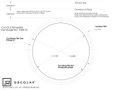
Cutout Detail of Supplied Template
Use the alphanumeric codes in the illustration and table to obtain the
cutout dimensions for the BB-1600. However, Crestron recommends that
the supplied template be used to avoid error.
CRESTRON
A A A A
BACK BOX CUTOUT
AAA A
VERTICAL MEASUREMENTS
V1 = 0.058 in (0.147 cm) typ.
V2 = 0.148 in (0.376 cm) typ.
V3 = 5.385 in (13.678 cm)
HORIZONTAL MEASUREMENTS
H1 = 7.440 in (18.898 cm)
H2 = 0.803 in (2.040 cm)
H3 = 5.835 in (14.821 cm)
H4 = 3.120 in (7.925 cm)
H5 = 1.200 in (3.048 cm)
H6 = 1.803 in (4.580 cm)
H7 = 3.835 in (9.741 cm)

Crestron BB-1600 Back Box
Installation Guide - DOC. 5835A Back Box: BB-1600Back Box: BB-1600 •• 11
Return and Warranty Policies
Merchandise Returns / Repair Service
1. No merchandise may be returned for credit, exchange, or service without prior
authorization from CRESTRON. To obtain warranty service for CRESTRON
products, contact the factory and request an RMA (Return Merchandise
Authorization) number. Enclose a note specifying the nature of the problem, name
and phone number of contact person, RMA number, and return address.
2. Products may be returned for credit, exchange, or service with a CRESTRON Return
Merchandise Authorization (RMA) number. Authorized returns must be shipped
freight prepaid to CRESTRON, Cresskill, N.J., or its authorized subsidiaries, with
RMA number clearly marked on the outside of all cartons. Shipments arriving freight
collect or without an RMA number shall be subject to refusal. CRESTRON reserves
the right in its sole and absolute discretion to charge a 15% restocking fee, plus
shipping costs, on any products returned with an RMA.
3. Return freight charges following repair of items under warranty shall be paid by
CRESTRON, shipping by standard ground carrier. In the event repairs are found to
be non-warranty, return freight costs shall be paid by the purchaser.
CRESTRON Limited Warranty
CRESTRON ELECTRONICS, Inc. warrants its Cresnet products, denoted by a "CN" prefix
model number, to be free from manufacturing defects in materials and workmanship for a
period of three (3) years from the date of shipment to purchaser. Disk drives and any other
moving or rotating mechanical parts are covered for a period of one (1) year. CRESTRON
warrants all its other products for a period of one year from the defects mentioned above,
excluding touchscreen display components which are covered for 90 days. Incandescent
lamps are completely excluded from Crestron's Limited Warranty. CRESTRON shall, at its
option, repair or replace any product found defective without charge for parts or labor.
Repaired or replaced equipment and parts supplied under this warranty shall be covered only
by the unexpired portion of the warranty.
CRESTRON shall not be liable to honor warranty terms if the product has been used in any
application other than that for which it was intended, or if it has been subjected to misuse,
accidental damage, modification, or improper installation procedures. Furthermore, this
warranty does not cover any product that has had the serial number altered, defaced, or
removed.
This warranty shall be the sole and exclusive remedy to the purchaser. In no event shall
CRESTRON be liable for incidental or consequential damages of any kind (property or
economic damages inclusive) arising from the sale or use of this equipment. CRESTRON
makes no other warranties nor authorizes any other party to offer any warranty, expressed or
implied, including warranties of merchantability for this product. This warranty statement
supersedes all previous warranties.
Trademark Information
All brand names, product names, and trademarks are the sole property of their respective owners.
Windows is a registered trademark of Microsoft Corporation. Windows95, Windows98 and
WindowsNT are trademarks of Microsoft Corporation.

Crestron Electronics, Inc. Operations Guide – DOC. 5835A
15 Volvo Drive Rockleigh, NJ 07647 12.00
Tel: 888.CRESTRON
Fax: 201.767.7576 Specifications subject to
www.crestron.com change without notice.
/