Page is loading ...

Turbo Ace MATRIX
1
Turbo Ace MATRIX
Quadcopter User Manual
V11
© 2013 Turbo Ace

Turbo Ace MATRIX
2
Table of Contents
INTRODUCTION ......................................................................................................... 4
1.1 Welcome to the World of Quadcopters ........................................................... 4
1.2 Important Instructions ...................................................................................... 4
1.3 Quick Start ....................................................................................................... 7
1.4 Features ............................................................................................................ 8
1.5 Specifications ................................................................................................... 8
1.6 Flight Controller Specifications ....................................................................... 8
1.7 Packing List ..................................................................................................... 9
1.8 Caution & Safety.............................................................................................. 9
1.9 DOA Claim .................................................................................................... 11
DIAGRAMS AND PARTS ......................................................................................... 12
2.1 Top View ....................................................................................................... 12
2.2 Profile View ................................................................................................... 13
2.3 Part Specifications ......................................................................................... 13
2.4 Technical Parameters ..................................................................................... 14
2.5 Parts List ........................................................................................................ 15
MATRIX SETUP......................................................................................................... 16
3.1 Unpacking the MATRIX ............................................................................... 16
3.2 Skid Landing Leg Assembly .......................................................................... 16
3.3 Mounting Propellers....................................................................................... 17
3.4 Battery Requirements & Installation ............................................................. 17
ELECTRONICS SETUP & ADJUSTMENT for Walkera Devo 10 Transmitter ....... 19
4.1 ESC Programming for Transmitter (A Must Setup For ARF) ....................... 19
4.2 Transmitter Calibration for Transmitter (Required Setup For ARF) ............. 21
4.3 Transmitter & Receiver Compatibility Table (For ARF Only) ..................... 26
4.4 Receiver, Flight Controller & Auto-stabilization Setup ................................ 27
4.5 Transmitter Settings (For ARF Only) ............................................................ 29
4.6 Transmitter Flight Control & Gain Adjustments (For ARF Only) ................ 30
4.7 MATRIX Wiring Connection Chart for Devo 10 & RX1002 ....................... 31
ELECTRONICS SETUP & ADJUSTMENT for Spektrum DX 8 Transmitter .......... 32
4.1 ESC Programming for Spektrum DX 8 Transmitter (A Must Setup For ARF)
.............................................................................................................................. 32
4.2 Transmitter Calibration for Spektrum DX 8 Transmitter (A Must Setup For
ARF) .................................................................................................................... 34
4.3 Transmitter & Receiver Compatibility Table (For ARF Only) ..................... 39
4.4 Receiver, Flight Controller & Auto-stabilization Setup ................................ 40
4.5 Transmitter Settings (For ARF Only) ............................................................ 42

Turbo Ace MATRIX
3
4.6 Transmitter Flight Control & Gain Adjustments (For ARF Only) ................ 43
4.7 MATRIX Wiring Connection Chart for Spektrum DX 8 & AR8000 ........... 45
ELECTRONICS SETUP & ADJUSTMENT for Futaba 14SG Transmitter............... 46
4.1 ESC Programming for Futaba 14SG Transmitter (A Must Setup For ARF) . 46
4.2 Transmitter Calibration for Futaba 14SG Transmitter (A Must Setup For
ARF) .................................................................................................................... 48
4.3 Transmitter & Receiver Compatibility Table (For ARF Only) ..................... 53
4.4 Receiver, Flight Controller & Auto-stabilization Setup ................................ 54
4.5 Transmitter Settings (For ARF Only) ............................................................ 56
4.6 Transmitter Flight Control & Gain Adjustments (For ARF Only) ................ 57
4.7 MATRIX Wiring Connection Chart for Futaba 14SG & R7008SB .............. 58
TESTING & OPERATIONS ....................................................................................... 59
5.1 Tie-Down Flight Test ..................................................................................... 59
5.2 Actual Flight Test & Training........................................................................ 60
5.3 LED Light Description for NAZA-Lite ......................................................... 62
5.4 LED Light Description for NAZA-V2 .......................................................... 63
5.5 Battery Tips .................................................................................................... 63
CAMERA MOUNT SETUP........................................................................................ 65
6.1 Gyrox Brushless Gimbal Setup ...................................................................... 65
6.2 MATRIX CAMERA MOUNT SERVO CONTROL SETUP ....................... 66
6.3 Flight Control Adjustment for Auto-Stabilization ......................................... 68
6.4 Basic Gain and Attitude Gain Adjustment for Stabilization .......................... 69
MAINTENANCE & REPAIR ..................................................................................... 70
7.1 Replacing Motors (For Repairs Only) ........................................................... 70
7.2 Replacing ESC (For Repairs Only)................................................................ 71
7.3 Replacing Extension Arms (For Repairs Only) ............................................. 72
FIXED ID BIND for Walkera Devo 10 ....................................................................... 74

Turbo Ace MATRIX
4
INTRODUCTION
1.1 Welcome to the World of Quadcopters
The MATRIX is spawning a new era in super quadcopter design. Its larger &
powerful motors, propellers and batteries offer up to three times the flight time and
payload of a traditional quad. The extra payload and flight time allow you to carry a
variety of cameras to produce unmatched cinematic quality video. Sporty low-profile
architecture, its triple carbon fiber deck supports an extra wide 1000mm wingspan
that folds down to fit inside an optional aluminum carrying case (no dismounting and
remounting of propellers, landing skids or gimbal required). The MATRIX's ideally
positioned camera mount on the nose offers wide angle views unobstructed by
propeller shadows, reflections and landing skids. Its well-balanced center of gravity,
with battery and gimbal position flexibility, greatly reduces swinging and improves
the video quality of the traditional under-mounted battery/gimbal design.
Quadcopters are loosely classified into several categories - from toys for amusement
to complex units for professional video, science & research. Now, a new class of
quadcopter is emerging for commercial applications. The Turbo Ace MATRIX is the
clear leader in this group with a list of outstanding features: advanced PC interface (so
you can update or customize the flight controller), cutting edge auto-stabilizing mode
for videographers, anti-vibration mounts, dynamically balanced motors for high
definition video production, and a host of other upgrades to improve reliability.
Unlike most quadcopters, the MATRIX is fully assembled and tested in the USA for
outdoor flight and it is ready to produce high quality video right out of the box. If you
are starting from scratch, the MATRIX RTF package even includes a paired
transmitter that is fully programmed and calibrated. If you already have a transmitter,
all you need is an ARF package. For additional cross-training, you can choose from
our optional professional Phoenix flight simulator, an easy-to-fly helicopter, and/or a
mini Walkera QR X350 quad. As with all Wow Hobbies’ featured RC helicopters,
MATRIX parts, upgrades and accessories are fully supported online and locally in the
USA.
1.2 Important Instructions
* Read the entire Matrix Instruction Manual on your included USB flash drive before you
operate the Matrix.

Turbo Ace MATRIX
5
* Follow the instruction manual for a tied down flight test on a bench. This is the safest way
to make sure the Matrix quadcopter has not been damaged during shipping.
* Foldable Matrix aluminum arms operate on guiding carbon tracks with keyed circular locks
on each end. To release the arm from the folded or operating ends of the track, please
unscrew the arm bolt counter-clockwise for a height of 1/8” before the lock will release.
If the bolt is not unscrewed to a sufficient height, you may risk scratching the carbon track.
* Prior to each takeoff, make sure the GPS antenna/compass is erected from the folded
position and screwed down.
* When mounting a propeller, use loctite and make sure the propeller clamp sits flat against
the top of the propeller. Even new propellers may need to be balanced if vibration shows on
video. Use a blade balancer with heavy gauge tape adhered to the underside of the blade for
balance. In bright sunlight, the GoPro 3 may show rolling shutter jello. Use ND8 filter if
necessary to slow down its shutter speed.
* Battery must be positioned by moving it backward and forward until the front and back
weights are balanced from the center point of the Naza flight controller. You can lift the
matrix up with a finger on each side of the matrix to check the balance (see manual for
details). The battery can be placed either on top or bottom of the Matrix.
* Camera must be balanced like a seesaw on a brushless gimbal, otherwise the gimbal motors
will be stressed and vibrate.
Maintaining the Matrix’s LiPo Batteries
* Matrix batteries are made up of 6 cells and each cell must be maintained between 3.7V to
4.2V. The total voltage for Matrix batteries should be maintained between 22.2V (3.7Vx6)
and 25.2V (4.2Vx6) without load. It’s very important to keep each cell above 3.7V. A cell is
at risk of being damaged or life shortened at 3.67V per cell without load.
* Each Matrix battery includes a yellow charging/discharging plug and a white balancing
plug. Both plugs must be plugged in to charge the battery. The yellow plug with thicker gauge
wires enables a faster charge rate, while the white plug with 1 small red wire and 6 small
black wires enables the charger to balance charge 6 individual cells. When all 6 cells reach
approximately 4.2V each for a total of 25.2V, the charger will automatically stop.
* A battery meter is one of the easiest way to monitor voltage for any LiPo battery.
There are seven pins on the battery meter. One of the pins is marked with a “-” symbol, which
should line up with the black wire of the battery’s white balancing plug. The first number
displayed is the total voltage of the battery, followed by each individual cell.

Turbo Ace MATRIX
6
Before & After Each Flight
* Attitude mode is the most reliable way to fly for experienced pilots, as it is not susceptible
to GPS interference. GPS mode is commonly used by beginners, but once more experience is
acquired, attitude mode is highly recommended (you can still use GPS mode as a backup).
When orientation is lost, do not panic. Just flip to GPS mode and let go of the cyclic stick,
and GPS will take over. Do not to attempt to recover the craft with the cyclic stick. There is a
certain time of the year in which solar flare may interfere with GPS. To recover the craft in
such a case, switch to manual (not attitude) mode. Please be aware that if the Matrix has
passed through airport X-ray screening, near a magnet or has been relocated more than 30
miles from where it was originally calibrated, the GPS may need to be recalibrated depending
on the geographic latitude at which you are located (see manual).
* Before each flight, always turn on the transmitter first, then plug in the Matrix battery.
Then, you need to allow enough time for the flight controller and GPS to warm up and
initialize. The Naza Lite takes approximately 2 minutes to warm up. The yellow LED light
will turn off when the Naza Lite is ready for use.
* After each flight, always unplug the Matrix battery first, then turn off the transmitter. If
you forget, the quadcopter and/or transmitter will continue to drain power and the battery will
be damaged.
Dos
* Do initialize the Matrix & takeoff from a large, leveled surface.
* Do implement a pre-flight checklist & use it consistently before takeoff.
* Do unplug the Matrix battery when maintaining or upgrading the quadcopter.
* Do dismount propellers if battery is plugged in while updating the flight controller.
Don’ts
* Don’t operate near people or pets & do not allow people to approach an operating
quadcopter.
* Don’t use magnets (e.g. magnetized screwdrivers & tools) in close proximity to the GPS
antenna/compass.
* Don’t attempt to catch a quadcopter.
1.3 Quick Start
The MATRIX has a convenient foldable arm / landing skid design. When you first
remove it from the box, please make sure that the GPS antenna (See diagram 2.5) is

Turbo Ace MATRIX
7
erected and properly tightened by turning the top locking cylinder in a clock-wise
direction. Next, loosen the arm screws located on top of the folding track. These
screws are keyed so they must be loosened and raised by about 1/8 of an inch in order
for the arms to fold, unfold the arms, and tighten them back in a clock-wise manner.
Make sure the round key located on the bottom of the screw is securely locked into
the circular key on the track. When it is properly locked in, it will prevent the arms
from accidentally folding during flight. Next, if you wish to fold the landing skid, you
may loosen the 2 side screws on each of the 4 legs. Pull the leg down to lengthen it.
Tighten the 2 screws back on each of the landing skid legs. Refer to section 5
TESTING & OPERATIONS (Please DO NOT install the propellers during the testing
procedure). Attach the battery to either on top or bottom of the Matrix. Lift the Matrix
up with one finger on each side from the center of Naza flight controller. Move the
battery until the Matrix is leveled like a see-saw with equal weight on both sides. See
Figure 3.4.4. It is important to note that the Matrix will not fly properly and may lose
control and crash if the center of gravity is not balanced at the middle of the Naza
flight control. Turn on the transmitter and within 2 seconds plug in the MATRIX
battery to bind. If your unit comes with DJI NAZA, please observe the blinking
yellow LED light located behind the quad, which indicates the controller is in warm
up stage. Wait for about 2 minutes until the yellow light stops flashing. Please check
the LED light description at section 5.3 and 5.4. Attitude mode is the most reliable
way to fly for intermediate to advance level pilots as all GPS is susceptible to
interference and sun spots activities. However, GPS remains to be the easiest and the
safest way to fly for beginners. Select the attitude mode from your transmitter, if you
are a trained pilot and use the GPS mode as a backup. Move both sticks of the
transmitter together in one action down to the lower right or left corner to start the
motors. Release right stick and immediately give the left stick about 10% throttles so
the motors will not cease. It will not lift off until the throttle stick passes 50%. Have
an experienced pilot test fly it on a bench while tied down. No defective claim is
allowed if the unit is crashed, so please be very careful.
1.4 Features
Extra wide 15-inch propellers for optimum flight time
High payload
High efficiency voltage with 6 cells Li-Po battery
Unobstructed front positioned camera mount
Center of gravity rolling camera compensation
Quick foldable design for easy portability

Turbo Ace MATRIX
8
Advanced Multi-Counter-Rotating Rotor System designed for outstanding
stability & performance
Intelligent Programmable Flight Controller
Built-in Altitude Hold when throttle stick is released at 50% Throttle
Flight Controller with PC software interface
Dual Flight Mode: Sport Flying Mode & Auto Leveling Aerial Video Mode
Advanced Gyro with 6-DOF Motion & MEMS Sensor Technology
Full Compatibility with Standard 2.4GHz Systems
4 Dynamically Balanced C4234 Brushless Motors with outstanding power and
minimal vibration
4 Independent 40A ESCs for Outstanding Performance, Reliability & Ease of
Maintenance
Square Anti-Twist Mount Impact-Resistant Propellers with low noise operation
High Payload suited for professional camera & video equipment
Optional Single Axis Quadruple Anti-Shock Camera Mount (available)
Optional High Capacity 8000mAh Batteries for extended flight (available)
Optional FPV Integration (available)
Optional Sports Mode for faster flight capability
1.5 Specifications
Three models: MATRIX Lite, MATRIX Silver, and MATRIX Black
Dimensions including propellers: 1000 mm × 392 mm × 135 mm
Motor: 4 x 42mm Outrunner Brushless Motors
ESC: 4 x 40A Electronic Speed Controllers
Propellers: 2 x CW and 2 x CCW, 15 inches carbon
Receiver & Transmitter Requirements: 2.4GHz 6 to 14 Channel RX/TX Pair
Standard Battery: LiPo 6S (22.2v) 5300mAh 20C 1P. Flight time 15 min
Optional Battery: LiPo 6S (22.2v) 8000mAh 20C 1P. Flight time 25 min
Weight Without Battery & Camera mount:3.5 lbs
Maximum Payload: 3.5 lbs. For proper operation and stability please limit the
payload to 2.5 lbs.
Wind Tolerance: Class 5
1.6 Flight Controller Specifications
Supported Multi-rotor
Quad-rotor I4, X4 / Hex-rotor I6, X6, IY6, Y6
Supported ESC output
400Hz refresh frequency
Recommended Transmitter
PCM or 2.4GHz with a minimum of 4 channels

Turbo Ace MATRIX
9
Working Voltage Range
MC:4.8V~5.5V
VU: 7.2V ~ 26.0 V (recommend 2S ~ 6S LiPo)
Power Consumption
MAX1. 5W (0.3A@5V)
Normal:0.6W (0.12A@5V)
Operating Temperature
-10°C ~ 50°C
Assistant Software System Requirement
Windows XP sp3 / Windows 7
Max Yaw Angular Velocity
200°/s
Max Tilt Angle
45°
Ascent / Descent
±6m/s
Weight
MC:25g
VU:20g
GPS:21.3g
Dimensions
MC: 45.5mm x 31.5mm x 18.5mm
VU: 32.2mm x 21.1mm x 7.7mm
GPS & Compass 46mm(diameter)x9mm
Built-In Functions
Three Modes Autopilot
Enhanced Fail-safe
Low Voltage Protection
S-Bus Receiver Support
2-axle Gimbal Support
1.7 Packing List
USB 8GB Flash Drive with test flight video, application software and the
MATRIX User Manual
1 x Turbo Ace MATRIX Quad Flyer (3 x Body Plates – Top Cover, Middle,
Bottom, 4 x Motors, 4 x ESC, Flight Controller)
2 x CCW Propellers (1555 Type) & 2 x CW Propellers (1555R Type)
Programming USB-to-Micro USB Cable to link to your PC
2 x Velcro Battery Strap (on Matrix) 1 x Velcro Battery Strap
Batteries: Included with RTF Package but not included with ARF Package
Receiver: Included with RTF Package but optional on ARF Package
1.8 Caution & Safety
As the operator of the Turbo Ace MATRIX, it is your responsibility to follow all
proper procedures, protocols and precautions to ensure the safe operation of the
MATRIX. The operator must wear safety glasses and any bystanders must be
protected in a safe area. Do not operate the MATRIX in the proximity of

Turbo Ace MATRIX
10
children, pets, cars and other vulnerable property. The owner and the operator
of the MATRIX assumes all liability for any damages caused in the operation of
the MATRIX, including but not limited to personal injury, equipment and
property damage.
If your package includes a transmitter radio, do not pull on the transmitter’s
antenna when removing it from the foam packaging tray. Remove the
transmitter by pulling on the neck strap holder.
Since the MATRIX propellers are dismounted for shipping purposes, you must
first follow the setup instructions in this user manual to mount the propellers. Any
attempt to skip procedures will end in a bad crash.
Do not be tempted to fly a new and large RC aircraft, such as the MATRIX,
out of the box, especially after shipping. Prior to its maiden flight, please tie
the MATRIX down to a stationary workbench for 3 battery test flights. Any
crashed aircraft is not eligible for dead-on-arrival or any other defective
equipment claims. If you are new to RC equipment, please seek the help of an
experienced RC equipment operator to prevent damage and injury.
If you have purchased a MATRIX ARF package, you must first program the
end points of each ESC then calibrate your transmitter to the MATRIX (See
Section 4.2). If you are using your own transmitter you must reprogram each
ESC independently. (See Section 4.1). Any attempt to fly without proper
transmitter calibration and ESC programming will result in a crash and it will
invalidate any DOA claim. If you have purchased an RTF (ready-to-fly) unit with
transmitter, please ignore these steps.
Additional Velcro should be added on the flight battery to prevent the battery
sliding from side to side.
Operator must tie down MATRIX and remove all propellers when it is
hooked up to a computer. Any incorrect settings or values may trigger an
accidental motor startup. Turbo Ace, its distributors and dealers are not liable for
any damages caused by mishandling of the MATRIX and its associated
equipment.
Operator should use Loctite to secure all necessary screws on the MATRIX,
excluding propeller locking screws. Blue Loctite can be applied directly to the
screw and should not come in contact with any plastic propellers or parts which
will crack during flight. Please do not use red Loctite, as it can only be removed
with extreme heat.

Turbo Ace MATRIX
11
1.9 DOA Claim
Even though the main assembly with attached electronics has been assembled and
tested in the USA before it is shipped to you. If your package includes a receiver or
transmitter, the whole package will be tested as a complete set. If your order does not
include a transmitter, you will be required to program the end points of each ESC and
calibrate your transmitter.
DOA (Dead-On-Arrival) must be claimed within 24 hours of receipt.
Do not return any products without authorization. If you need to return a product
for service, you will need to acquire a Return Merchandise Authorization (RMA
Number) through e-mail ([email protected]) or our website. If we don’t
have a record of your request, your returned product will be rejected.
No DOA claims can be made when you pick up your MATRIX from our store
because it will be test flown live before you take it home.
No DOA claims can be made once the device has been crashed, including, but
not limited to, blades tipping on the ground or any equipment failure after
shipping that was not uncovered by skipping the 3 battery test flights with the
tie-down bench test.
There is no warranty, return or exchange on all RC products.

Turbo Ace MATRIX
12
DIAGRAMS AND PARTS
2.1 Top View

Turbo Ace MATRIX
13
2.2 Profile View
2.3 Part Specifications
No.
Part
Specifications
QTY
Units
Remarks
1
Chassis
Carbon Fiber
1
SET
2
Arm
High Strength
Aluminum Tubing
4
PCS
3
Skid Landing
Carbon Fiber
4
SET
4
Motor
C4234 400KV
Brushless Motor
4
PCS
5
Propeller
1555 (Normal),1555R
(Reverse)
15-inch Carbon Fiber with
high fiber & low resin content
4
PCS
6
Head Hangers
Elastic Damping, Shock
Absorber Suspension
1
SET
7
ESC
6S 40A high-Speed Electronic
Controller
4
PCS
8
Flight Control
System
DJI NAZA- LITE / DJI
NAZA V2
1
PCS

Turbo Ace MATRIX
14
2.4 Technical Parameters
Width
Diameter From Outer Edges of Motors
765 mm
±3mm
Extended
Width
Diameter From Extended Propellers
1111 mm
Motors Center
to Center
Diameter From Center of Motor to Center
of Motor on Opposite Side
724 mm
±3mm
Height
Bottom of Skid Landing to Top of Motor
Cover (including GPS Compass)
132 mm
(200 mm)
Propeller
2 x CW & 2 x CCW
381 mm
Battery
LiPo 6S
22.2V
Single Weight
No battery, receiver, load
3.3 lbs
±10g
Flight Distance
Limited by Sight & the
Receiver/Transmitter
Flight Time
6S 5300mAh, 1P Battery, receiver
20 minutes
No wind hover
Wind strength
≤5
Class

Turbo Ace MATRIX
15
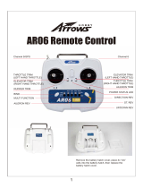
2.5 Parts List

Turbo Ace MATRIX
16
MATRIX SETUP
3.1 Unpacking the MATRIX
Remove all MATRIX contents from the box. To avoid damaging the transmitter
antenna, do not pull on it to remove the transmitter out of the box. Instead, pull on the
neck strap to safely remove the transmitter from the box.
3.2 Skid Landing Leg Assembly
Figure 3.2-1 Four sets of Skid Landings disassembled
(1) Please skip this section if your unit comes fully assembled. Take two 15mm
3.0mm posts (Female/Female) and screw on both sides of the skid landing plates
on the bottom two holes (as indicated in Figure 3.2-2).
(2) Take one inner skid bracket and screw on both sides of the skid landing plates on
the top hole (as indicated in Figure 3.2-2).
(3) Repeat steps 1 – 2 for the remaining three Skid Landings.
15 mm post
15 mm post
Inner skid bracket
Figure 3.2-2 Four sets of Skid Landings assembled
Figure 3.2-3 One Skid Landing Leg

Turbo Ace MATRIX
17
3.3 Mounting Propellers
There are a total of 4 propellers in your package.
(1) Unscrew and remove the propeller screws from the motor and remove the motor
cover.
(2) Due to the precision needed to reduce vibration, the propellers are design to fit
tightly on the motors. Using the figure below, insert labeled propeller to
corresponding motor. Motors #1 & #3 use Counter Clockwise propellers and
motors #2 and #4 use Clockwise propellers. Failure to mount the correct
propeller(s) on the designated motor will result in a crash.
(3) Over tightening the motor cover screw may damage the motor aluminum threads.
Repeat this for all 4 propellers.
3.4 Battery Requirements & Installation
(1) Standard Battery: 6-S LiPo, 22.2V, 5300mAh, 35C, 1P
(2) Optional Extended Flight Battery: 6-S LiPo 22.2V, 8000mAh, 25/50C, 1P
(3) Release the two wide Velcro battery straps on the tail of the MATRIX bottom
plate. Make sure a Velcro strip is added to the battery and the body of the Matrix
to prevent it from sliding. Secure it with the two wide Velcro battery straps.
(4) Move battery forward/backward until weight is equal from center of the Naza
flight controller. You can balancing the Matrix like a see-saw by lifting it up

Turbo Ace MATRIX
18
with fingers on each side of the Naza Flight controller until it is leveled. Your
camera, propellers and all devices must be installed before balancing. See
diagram 3.4-1
(5) Do not plug in the battery at this time.
Figure 3.4-1 Balance at center of gravity

Turbo Ace MATRIX
19
ELECTRONICS SETUP & ADJUSTMENT for
Walkera Devo 10 Transmitter
If you have purchased an RTF package, please skip Section 4.1 through 4.5
because all settings are already complete and your MATRIX and transmitter have
been paired and test flown as a set. Unless you are familiar with the settings, any
changes might override the factory’s setting and disable the aircraft, affecting its
performance and flight reliability.
If you have purchased an ARF package, you must complete Section 4.1 ESC
Programming and Section 4.2 Transmitter Calibration. MATRIX ESCs needs to
reprogram independently. Also, in order for a flight controller to work properly, your
specific transmitter has to be calibrated to work with each new MATRIX. Crashes
will be imminent if you skip these one-time procedures to match a MATRIX with a
transmitter.
4.1 ESC Programming for Transmitter (A Must Setup For ARF)
Video Instruction:
How to calibrate the ESC for MATRIX:
https://www.dropbox.com/s/zcf72jgoeng92c9/How%20to%20calibrate%20the%20ES
C.MP4
Please skip this ESC programming step if you have purchased RTF unit, since all
ESC have been re-programmed. Please follow the steps below very carefully, as they
will only take a few minutes.
(1) Very important: Remove all 4 propellers from the motors for safety.
(2) Double check to make sure all ESC connectors are marked/labeled (#1
through #4 matching the connectors on the flight controller #1 through #4)
so that you will be able to keep track of the corresponding connectors when
you need to put them back later.
(3) Disconnect all 4 ESC connectors from the NAZA flight controller so they
may not interfere with each other’s programming.
(4) Move the throttle stick all the way down. Now turn on the transmitter.

Turbo Ace MATRIX
20
(5) Disconnect X3 on NAZA flight controller and plug into AUX1 on the
receiver.
(6) Insert one of the labeled ESC connectors into the receiver’s throttle channel
port while watching for the correct polarity. Black/dark brown wires are
usually on the edge of the receiver. Please verify polarity in your receiver
manual if you are not using the stock Walkera receiver.
(7) Move the throttle stick all the way up.
(8) Within 3 seconds, connect the battery to the MATRIX’s battery plug (The
MATRIX battery plug is still connected to all 4 ESCs but only one ESC
should be connected to the receiver at a time.)
(9) When the ESC makes 1 beeping sounds, immediately move the throttle stick
all the way down. The ESC will then make 2 beeping. (If you did not hear
the 1 beeping sounds when entering programming mode or you did not hear
2 beeping after the ESC have completed its programming then you need to
move throttle all the way down and disconnect the battery from the
MATRIX battery plug and repeat from step #6 to #9 for the ESC.) If you did
not experience any problems, then you have completed programming on this
ESC which now retains the high and low end point data in its memory.
Disconnect the battery from the MATRIX’s battery connector then
disconnect the ESC connector from the receiver.
(10) Repeat this process for each ESC from Step#6 through Step#9. Please make
sure you have programmed all 4 ESCs by starting from the #1 labeled ESC
and finishing with #4 labeled ESC. Your transmitter power should remain in
the power on position throughout the entire process of programming all 4
ESCs.
(11) After you have successfully re-programmed all 4 ESCs, unplug the battery
from the MATRIX battery plug then turn off the transmitter.
(12) Insert the 4 ESC connectors, labeled #1 through #4 back to corresponding
M1 through M4 ports on your NAZA flight controller. The black/dark
brown wire (-) for each of the ESC connectors are closest to the red NAZA
label of the flight controller.
/