Page is loading ...

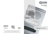
T200EN
rev.0204
295 Series
Audio
door entry system
Kits
4+'n' wires installation
Instructions manual
Golmar se reserva el derecho a cualquier modificación sin previo aviso.
Golmar se réserve le droit de toute modification sans préavis.
Golmar reserves the right to make any modifications without prior notice.
golmar@golmar.es
www.golmar.es

First of all we would like to thank and congratulate you for the purchase of this product
manufactured by Golmar.
The commitment to reach the satisfaction of our customers is stated through the ISO-9001
certification and for the manufacturing of products like this one.
Its advanced technology and exacting quality control will do that customers and users enjoy with the
legion of features this system offers. To obtain the maximum profit of these features and a properly wired
installation, we kindly recommend you to expend a few minutes of your time to read this manual.
O
O
O
To make a call the visitor should press the push button corresponding to the apartment he wishes
to contact. An acoustic tone will be heard confirming the call as the push button is pressed. At
this moment the call will be received at the telephone in the dwelling.
To establish communication pick up the telephone handset.
To open the door, press the door release push button at any moment.
O
O
O
Do not use excessive force when tightening the transformer connector screws.
Install the equipment without the power connected. Disconnect from power before any system
modification. Check that the input voltage is lower than 230Va.c.
Before to connect the system, check the connections between door panel and telephones, and
the transformer connection. Do always follow the enclosed information.
O
O
O
O
Audio system with 4 + N wires installation.
Just 1 TF-104 transformer (12Va.c., 1.5A).
Electronic call with acoustic acknowledgement signal.
a.c. lock releases activation.
OUp to three telephones in the same apartment.
1
INTRODUCTION
SYSTEM CHARACTERISTICS
SYSTEM OPERATION
STARTING RECOMMENDATIONS
2DOOR PANEL INSTALLATION
mbedding box positioning.
E
1650
1850
1450
The upper part of the door panel should be placed at 1,65m. height roughly. The hole dimensions
will depend on the number of door panel modules.
The door panel has been designed to be placed under most of the environmental conditions.
However it's recommended to take additional cautions like rainproof covers.
1
140
235
57
Modules
W
H
D
2
280
235
57
3
420 mm.
235 mm.
57 mm.
reparing the cables entry.
P
Break the bottom flange to pass the cables through. In case of door panels
with more than one embedding box, break the side flanges and
attach the embedding boxes using UC junctions.

4
3
DOOR PANEL INSTALLATION DOOR PANEL INSTALLATION
old the door panel on the embedding box.
H
Insert the hinge in the embedding box lockers.
Press the hinge ends to insert them in the door panel
lockers as shown.
oor panel wiring.
D
Open the terminal connector cover and connect
the wires as shown on the installation diagram.
In case of door panels with more than one module
link the main module with the push buttons modules
through the UC junctions and wire them as shown
on page 7.
lace the embedding box.
P
Pass the wiring through the hole made in the bottom part
of the embedding box. Level and flush the embedding
box. Once the embedding box is placed, remove the
protective labels from the attaching door panel holes.
Telephone Door panel
lace the nameplate labels.
P
inal adjustments.
F
If after starting the system it's considered that
the audio volume isn't correct, proceed
with the necessary adjustments as shown.
lose the door panel.
C
Fix the door panel to the embedding box
by using the supplied vandal resistant screws
and the special screwdriver.

POWER SUPPLY INSTALLATION
LOCK RELEASE INSTALLATION
5
nstalling the TF-104 transformer.
I
To install the transformer directly on the wall,
insert the fixing flanges.
Drill two holes of Ø6mm. and
insert the wallplugs.
Fix the transformer with the specified
screws.
The transformer can be installed on a DIN guide (3 units) simply pressing it.
To disassemble the transformer from the DIN guide, use a plain screwdriver to lever
the flange as shown on the picture.
The transformer must be installed in a dry and
protected place. It's recommended to protect
the transformer by using a thermo-magnetic
circuit breaker.
DIN 46277
ock release installation.
L
If the lock release will be installed in a metal door, use a
Ø3,5mm. drill and tap the hole. In case of wood door,
use a Ø3mm. drill.M 4 x 8
f3,5 x 25
DIN-7972
DIN-963
TELEPHONE INSTALLATION
6
a.
b.
c.
d.
e.
f.
g.
Telephone handset.
Speaker grille.
Microphone hole.
Subjection hole.
Telephone cord connectors.
Door release push button.
Hook switch.
a
d
c
e
e
g
f
b
To open the telephone insert
a plain screwdriver into the slots and
rotate it as shown.
Avoid to place the telephone near to heating sources,
in dusty locations or smoky environments.
The telephone can be fixed using an electrical embedding
box or directly on the wall, as shown on the picture.
If the telephone will be installed directly over the wall,
drill two holes of Ø6mm. on the specified positions,
using 6mm. wallplugs and Ø3,5 x 25mm. screws.
Pass the installation wires through
the corresponding hole and
connect them as shown on the
installation diagrams.
Close the telephone as shown on the picture.
Once the telephone is closed, connect the handset
using the telephone cord and put it on the craddle.
escription of the T-900 telephone.
D
f3,5 x 25
DIN-7971
f3,5 x 25
DIN-7971

INSTALLATION DIAGRAM 7INSTALLATION DIAGRAM
8
Tel. 1 Tel. 1 Tel. 2
Tel. 1 Tel. 1 Tel. 2
Tel. 2 Tel. 3 Tel. 4
Tel. 2 Tel. 3 Tel. 4
Tel. 3 Tel. 5 Tel. 6
Tel. 3 Tel. 5 Tel. 6
Tel. 4 Tel. 7 Tel. 8
CN1
CN1
CN1
CN1
N8 N8
N8 N8
N7 N7
N7 N7
N6 N6
N6 N6
N5 N5
N5 N5
0 0 0
0 0 0
0 0 0
N4 N4
N4 N4
N3 N3
N3 N3
0 0 0
0 0 0
N2 N2
N2 N2
N1 N1
N1 N1
0 0 0
0 0 0
CN2 CP
-
~1 ~2 CN2 CP
-
~1 ~2
CN2
CV CPP
-
~1 ~2
PE-295/3 PE-295/6 ~ CA-295/6
PE-295/4 PE-295/8 ~ CA-295/8
N1
N3
N5
N1 N2
N4
N6
N3
N5
N1 N1 N2
N4
N6
N8
N3 N3
N5 N5
N7 N7
inking the push buttons modules.
L
ush buttons wiring.
P
In case of door panels with more than one module, wire the push buttons modules
with the main module as shown below.
IMPORTANT NOTICE: the enclosed pictures draw the correspondence between each push
button and its corresponding terminal on the CN1 connector. Terminals without arrow
are not connected.
Main module 1st push buttons module 2nd push buttons module
SECTIONS CHART
ind. 1
ind. 2
0
0
10
10
5
5
3
3
P1
P1
TF-104
SEC
~~
PRI ~~
Main
CN2
CV CPP
-
~1 ~2
PE-295/xx panel
ne access door.
O
ections chart.
S
0, ind, 5, , 10, , P, P1 0,25mm² 0,50mm²
0,50mm² 1,00mm²
1,00mm² 2,50mm²
Terminal 100m.
Maximum distance
300m.
–, 3
~1, ~2, CV
For longer distances than the specified contact with your distributor.

TROUBLESHOOTING HINTS
9
CV CPP
-
~1 ~2
ind.
0 010 105 53 3P1 P1
arallel telephones installation.
PThe maximum number of telephones placed
in the same apartment is three.
For each telephone placed in parallel
the section corresponding to the call wire
must be doubled.
OPTIONAL CONNECTIONS
xternal lock release activation.
E
The lock release can be activated at any moment by using
an external push button, that must be connected between
'–' y 'P' terminals of the main module.
This function will allows to exit from the building
being not necessary the use of a key.
ONothing operates.
wCheck the output transformer voltage between SEC terminals: it should have 12 to 17Va.c. If
not, disconnect the transformer from the installation and measure again. If it's correct now,
it means there is a short circuit in the installation: disconnect the transformer from mains
and check the installation.
OInappropriate audio level.
wAdjust the level volumes as shown on page 4. In case of feedback, reduce the audio levels
until feedback fade out.
ODoor open function no operates.
wDisconnect the lock release from the main module and short-circuit terminals ' ' and 'P': at
that moment the output voltage between terminals 'CV' and '~2' of the main module
should be 12Va.c. If it's so check the lock release, its wiring and the wiring of the terminal
'P' from the main module to the telephones. If these tests don't solve the problem, replace
the main module.
ONo telephones receive the call or acknowledgement call signal is not reproduced.
wCheck that the call wires are connected to a valid terminals. In case of door panels with push
buttons modules, check the 'CP' terminal connection to the main module. Both procedures
are described on page 7.
–

Golmar se reserva el derecho a cualquier modificación sin previo aviso.
Golmar se réserve le droit de toute modification sans préavis.
Golmar reserves the right to make any modifications without prior notice.
golmar@golmar.es
www.golmar.es
/

