Page is loading ...

2070 x 600
50/50
2070 x 600
70/30
2250 x 600 Tall
50/50
2250 x 600 Tall
70/30
For Internal Use: FI.WR.INS.041 | WKIN00141_TOWER_600_2DrFridgeFreezer_Rev4.indd
TOWER UNIT
600 2 Door
Fridge/Freezer
Assembly Guide

BEFORE YOU START
INSTALLATION
SHOULD BE
PERFORMED BY A
COMPETENT
PERSON ONLY.
THIS PRODUCT COULD
BE DANGEROUS
IF INCORRECTLY
INSTALLED
REQUIRED TOOLS
NOT to be used
with CAM DOWEL
& CAM LOCK
Panel B
x2 End Panel
Panel C
x2 Base Panel
Panel E
x2 Rail
Appliance Shelf
x1
Legs
x5
Frontal (packed separately)
x2
70/30 OPTION
50/50 OPTION
Sml L Bracket
(FF) x4
Hinge Mounting Plate
x4 Inc Screws
Hinge
x4 Inc Screws
(U) x2
Fixing Plate
(F) x16
Wooden Dowel
(L) x24
15mm
Screw
(G) x16
Cam Dowel
(Expanding)
(H) x12
Cam lock
(M) x4
Cover Cap
(K) x10
30mm
Screw
(N) x2
Door Buer
Lge L Bracket
x2
(Z) x24
Shelf Peg
Plastic
For Internal Use: FI.WR.INS.041 | WKIN00141_TOWER_600_2DrFridgeFreezer_Rev4.indd
Page 1
TOWER UNIT
600 2 Door
Fridge/Freezer
Assembly Guide

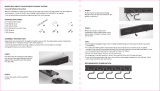
Step 1.
Seat dowel (F) into holes in
both end panels (B) as shown.
Step 2.
Seat cam dowel (G) into
holes in both end panels (B)
as shown.
DOWEL (F)
& CAM DOWEL (G)
LOCATION DETAIL
Step 3.
Attach panels (C) and (E) to panels (B),
using cam dowel (G) and also using Dowels (F) (in orange)
in positions as shown.
NB. All CAM LOCK (H) are to be positioned facing
the outside of the unit carcass, for ease of tightening.
Step 4.
Join panels (C) & (E) to (B).
Insert cam lock (H).
Do NOT tighten until Step 6.
Do not use power tools with
cam dowel (G) or cam lock (H)
G
F
F G
G F F G
B
GFFG
GFFG
B
G
F
F
G
F
F
G
F
F
G
F
F
Seat (G)
cam dowel
into hole as
shown.
B
B
C
C
View from underside
View from underside
H
G
G
H
B
E
E
C
B
C
For Internal Use: FI.WR.INS.041 | WKIN00141_TOWER_600_2DrFridgeFreezer_Rev4.indd
Page 2
TOWER UNIT
600 2 Door
Fridge/Freezer
Assembly Guide

B
B
Step 5.
Secure each of the legs
into place with
2 x 15mm screws (L) per leg
Step 7
Push leg rmly down into leg base.
Adjust legs to 155mm before turning carcass
upright. Once in situ level accordingly.
Step 6.
Lightly hit centre peg of leg base with hammer
until ush with the leg base.
Ensure legs are rotated as shown so that part
of it is supporting the end panels (B).
Front legs should have at edge to the front.
Front
Front
C
C
B
B
C
L
L
C
B
C
B
Leg position diagram
For Internal Use: FI.WR.INS.041 | WKIN00141_TOWER_600_2DrFridgeFreezer_Rev4.indd
Page 3
TOWER UNIT
600 2 Door
Fridge/Freezer
Assembly Guide

Step 8.
Attach hinge plates onto end panels (B) In
locations shown using 8 x 15mm screws (L)
hinge side to be mounted in accordance
to customer kitchen plan.
N.B.
For appliance shelf, secure to panel (B)
using 4 x brackets (FF) locate according to
customer appliance requirements.
70/30
HINGE
POSITION
See Customer Kitchen Plan for siding.
Dimensions relevant for left and right scenario.
50/50
HINGE
POSITION
Example
locations
ONLY
70/30
1826mm 1826mm
846mm
1086mm
626mm
866mm
126mm 126mm
1794mm 1794mm
814mm
1054mm
594mm
834mm
94mm 94mm
50/50
Example
locations
ONLY
B B
L
L
L
L
L
L
L
L
FF FF
FF FF
From Base From Base
For Internal Use: FI.WR.INS.041 | WKIN00141_TOWER_600_2DrFridgeFreezer_Rev4.indd
Page 4
TOWER UNIT
600 2 Door
Fridge/Freezer
2070
Assembly Guide

Step 8.
Attach hinge plates onto end panels (B) In
locations shown using 8 x 15mm screws (L).
Hinge side to be mounted in accordance to
customer kitchen plan.
N.B.
For appliance shelf, secure to panel (B)
using 4 x brackets (FF) locate according to
customer appliance requirements.
70/30
HINGE
POSITION
50/50
HINGE
POSITION
Example
locations
ONLY
Example
locations
ONLY
70/30
2006mm 2006mm
846mm
1026mm
626mm
806mm
126mm
126mm
1974mm 1974mm
814mm
994mm
594mm
774mm
94mm
94mm
50/50
B B
L
L
L
L
L
L
L L
FF FFFF FF
See Customer Kitchen Plan for siding.
Dimensions relevant for left and right scenario.
From Base From Base
For Internal Use: FI.WR.INS.041 | WKIN00141_TOWER_600_2DrFridgeFreezer_Rev4.indd
Page 5
TOWER UNIT
600 2 Door
Fridge/Freezer
2250
Assembly Guide

Secure tower to the wall using L brackets.
Use 2 x 15mm screws (L) to secure each of the L brackets
to the cabinets at either side. Then screw through into the
wall as shown.
Screws for xing to walls are not provided as these
vary depending on your wall material and construction.
Ensure appropriate xings for wall constructions are
used.
Secure tower to the wall using screws through rail panel (E) into the
wall as shown.
Screws for xing to walls are not provided as these vary depending on
your wall material and construction. Ensure appropriate xings for wall
constructions are used.
Securing to Adjacent Units
Screw into any side units using
the 30mm screws (K) provided to secure to unit.
Screw just to the rear of the Hinge Mounting Plate,
at the top and bottom of both sides of the unit,
place a cover cap on the head to conceal it.
L
L
E
E
K
For Internal Use: FI.WR.INS.041 | WKIN00141_TOWER_600_2DrFridgeFreezer_Rev4.indd
Page 6
TOWER UNIT
600 2 Door
Fridge/Freezer
Assembly Guide

Fixing plates
See Customer Specic Kitchen Plan
For Tower Frontals
Fixing plates
Step 9.
Insert hinge where required
in holes as shown.
Step 10.
Secure hinges by tightening
2 x screws with hinge dowels
attached. These are already
positioned within the hinges.
Step 12.
Adjust hinge to suit. As shown below.
U
U
Step 11.
Align doors to join together
using 2 x xing plates (U)
to the back of both frontals
ensure a 3mm gap is
maintained between each
frontal once xed together.
Screw in place using 4 x 15mm
screws per xing plate.
Hinge cover caps
The top and bottom
hinges MUST be
adjusted to the SAME
STRENGTH.
View from Inside of Carcass
To adjust hinge using a screw
driver, tighten or loosen as
required at points 1 & 2.
Point 1 - In - Out
Point 2 - side - side
1
2
FRONTAL HINGE
ADJUSTMENT
To Release door
Pull catch as shown,
to release hinge
from the hinge
plate.
Step 13.
Fit cover caps to hinge.
Adjust Softclose to suit.
For Internal Use: FI.WR.INS.041 | WKIN00141_TOWER_600_2DrFridgeFreezer_Rev4.indd
Page 7
TOWER UNIT
600 2 Door
Fridge/Freezer
Assembly Guide
/