TANDBERG D1392602: Conquer Connectivity Challenges with Ease
This remarkable device, the TANDBERG D1392602, is a versatile tool that empowers you to effortlessly manage and monitor your TANDBERG Video Portal system. With a user-friendly command interface accessible via RS-232 or Telnet, you can harness the full potential of your video conferencing system.
Key capabilities include system configuration, status monitoring, and troubleshooting. Configure network settings, adjust audio/video preferences, and manage user accounts with ease.


-
 1
1
-
 2
2
-
 3
3
-
 4
4
-
 5
5
-
 6
6
-
 7
7
-
 8
8
-
 9
9
-
 10
10
-
 11
11
-
 12
12
-
 13
13
-
 14
14
-
 15
15
-
 16
16
-
 17
17
-
 18
18
-
 19
19
-
 20
20
-
 21
21
-
 22
22
-
 23
23
-
 24
24
-
 25
25
-
 26
26
-
 27
27
-
 28
28
-
 29
29
-
 30
30
-
 31
31
-
 32
32
-
 33
33


TANDBERG D1392602: Conquer Connectivity Challenges with Ease
This remarkable device, the TANDBERG D1392602, is a versatile tool that empowers you to effortlessly manage and monitor your TANDBERG Video Portal system. With a user-friendly command interface accessible via RS-232 or Telnet, you can harness the full potential of your video conferencing system.
Key capabilities include system configuration, status monitoring, and troubleshooting. Configure network settings, adjust audio/video preferences, and manage user accounts with ease.
Ask a question and I''ll find the answer in the document
Finding information in a document is now easier with AI
Related papers
-
 TANDBERG D1320203 User manual
-
 TANDBERG Hub User manual
-
TANDBERG 3G GATEWAY 1 User manual
-
 TANDBERG Gatekeeper User manual
-
 TANDBERG Network Router 6213 User manual
-
 TANDBERG D1320202 User manual
-
 TANDBERG Video Portal Administrator's Manual
-
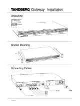 TANDBERG Gateway Installation guide
-
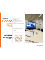 TANDBERG Codec 6000 MXP Reference guide
-
 TANDBERG Network Card D13639 User manual


Other documents
-
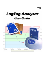 LogTag Recorders LogTag Analyzer Temperature Recorder User manual
-
LogTag Analyzer User manual
-
Cisco TelePresence X8.1.1 Administrator's Manual
-
Avaya 1000 Series Video Conferencing Systems User manual
-
-
Cisco Systems CTSSX2012XK9PRM User manual
-
 Perfectone Net Ware iP 300 User manual
-
-
Eltex TAU-72.IP Operating instructions
-
Gateway AG-168V User manual

