StarTech.com 110VDSLEXT2 User manual
- Category
- Network extenders
- Type
- User manual
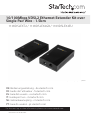
StarTech.com 110VDSLEXT2 extends your existing Ethernet network over existing copper phone lines, using VDSL2 technology to achieve data transfer speeds of up to 100Mbps over distances of up to 1.5 kilometers. Ideal for connecting remote buildings, surveillance cameras, or any other Ethernet-enabled device to your network.
StarTech.com 110VDSLEXT2 extends your existing Ethernet network over existing copper phone lines, using VDSL2 technology to achieve data transfer speeds of up to 100Mbps over distances of up to 1.5 kilometers. Ideal for connecting remote buildings, surveillance cameras, or any other Ethernet-enabled device to your network.


-
 1
1
-
 2
2
-
 3
3
-
 4
4
-
 5
5
-
 6
6
-
 7
7
-
 8
8
-
 9
9
-
 10
10
-
 11
11


StarTech.com 110VDSLEXT2 User manual
- Category
- Network extenders
- Type
- User manual
StarTech.com 110VDSLEXT2 extends your existing Ethernet network over existing copper phone lines, using VDSL2 technology to achieve data transfer speeds of up to 100Mbps over distances of up to 1.5 kilometers. Ideal for connecting remote buildings, surveillance cameras, or any other Ethernet-enabled device to your network.
Ask a question and I''ll find the answer in the document
Finding information in a document is now easier with AI
Related papers
-
 StarTech.com RK619WALLGB User manual
-
StarTech.com IREXT2 User manual
-
 StarTech.com RJ11EXT25 Datasheet
-
StarTech.com IES8100POEGB User manual
-
-
 StarTech.com 10/100 VDSL2 Ethernet Extender Kit over Single Pair Wire – 1km Owner's manual
-
StarTech.com ST121WHDST User manual
-
 StarTech.com 4 Port 10/100 VDSL2 Ethernet Extender Kit over Single Pair Wire - 1km User manual
-
StarTech.com ST121HDBT5 User manual
-
StarTech.com 410VDSLEXT2 User manual


Other documents
-
Repotec RP-VC111T Owner's manual
-
Allied Telesis MMC6006 Installation guide
-
CTC Union VDTU2-B110 User manual
-
Korenix JetCon 2502 User manual
-
Moxa IEX-402 Series User manual
-
-
MicroNet SP3501B Series User manual
-
Planet VC-201 User manual
-
Allnet ALL126AS2 User guide
-
SMC Networks SMC7800A/VCP User manual