Page is loading ...

Product Manual
BreezeMAX
®
PRO 6000
Release Number: 1.5
July 2012
P/N 216035

ii
Document History
BreezeMAX PRO 6000 Product Manual
Document History
Changed Item Description Date
This is the document’s first publication. May 2012
Accessing the Web
Management Interface
Section 3.2.1
Corrected IP addresses July 2012
Service Line
Section 9.4
Default for Enable DSCP spoofing is not
selected (DSCP spoofing disabled).
Certain configuration rules are applicable only
when working with DSCP Spoofing enabled.

iii
Legal Rights
BreezeMAX PRO 6000 Product Manual
Legal Rights
© Copyright 2012 Alvarion Ltd. All rights reserved.
The material contained herein is proprietary, privileged, and confidential and owned by Alvarion or its
third party licensors. No disclosure thereof shall be made to third parties without the express written
permission of Alvarion Ltd.
Alvarion Ltd. reserves the right to alter the equipment specifications and descriptions in this publication
without prior notice. No part of this publication shall be deemed to be part of any contract or warranty
unless specifically incorporated by reference into such contract or warranty.
Trade Names
Alvarion
®
, BreezeCOM
®
, WALKair
®
, WALKnet
®
, BreezeNET
®
, BreezeACCESS
®
, BreezeMAX
®
,
BreezeLITE
®
, 4Motion
®
, and/or other products and/or services referenced here in are either registered
trademarks, trademarks or service marks of Alvarion Ltd.
All other names are or may be the trademarks of their respective owners.
“WiMAX Forum” is a registered trademark of the WiMAX Forum. “WiMAX”, the WiMAX Forum logo,
“WiMAX Forum Certified”, and the WiMAX Forum Certified logo are trademarks of the WiMAX Forum.
Statement of Conditions
The information contained in this manual is subject to change without notice. Alvarion Ltd. shall not be
liable for errors contained herein or for incidental or consequential damages in connection with the
furnishing, performance, or use of this manual or equipment supplied with it.
Warranties and Disclaimers
All Alvarion Ltd. (“Alvarion”) products purchased from Alvarion or through any of Alvarion's authorized
resellers are subject to the following warranty and product liability terms and conditions.
Exclusive Warranty
(a) Alvarion warrants that the Product hardware it supplies and the tangible media on which any
software is installed, under normal use and conditions, will be free from significant defects in materials
and workmanship for a period of fourteen (14) months from the date of shipment of a given Product to
Purchaser (the “Warranty Period”). Alvarion will, at its sole option and as Purchaser's sole remedy, repair
or replace any defective Product in accordance with Alvarion' standard R&R procedure.
(b) With respect to the Firmware, Alvarion warrants the correct functionality according to the attached
documentation, for a period of fourteen (14) month from invoice date (the “Warranty Period”). During
the Warranty Period, Alvarion may release to its Customers firmware updates, which include additional
performance improvements and/or bug fixes, upon availability (the “Warranty”). Bug fixes, temporary
patches and/or workarounds may be supplied as Firmware updates.
Additional hardware, if required, to install or use Firmware updates must be purchased by the Customer.
Alvarion will be obligated to support solely the two (2) most recent Software major releases.
ALVARION SHALL NOT BE LIABLE UNDER THIS WARRANTY IF ITS TESTING AND EXAMINATION DISCLOSE
THAT THE ALLEGED DEFECT IN THE PRODUCT DOES NOT EXIST OR WAS CAUSED BY PURCHASER'S OR
ANY THIRD PERSON'S MISUSE, NEGLIGENCE, IMPROPER INSTALLATION OR IMPROPER TESTING,
UNAUTHORIZED ATTEMPTS TO REPAIR, OR ANY OTHER CAUSE BEYOND THE RANGE OF THE INTENDED
USE, OR BY ACCIDENT, FIRE, LIGHTNING OR OTHER HAZARD.

iv
Legal Rights
BreezeMAX PRO 6000 Product Manual
Disclaimer
(a) THE SOFTWARE IS SOLD ON AN “AS IS” BASIS. ALVARION, ITS AFFILIATES OR ITS LICENSORS MAKE
NO WARRANTIES, WHATSOEVER, WHETHER EXPRESS OR IMPLIED, WITH RESPECT TO THE SOFTWARE
AND THE ACCOMPANYING DOCUMENTATION. ALVARION SPECIFICALLY DISCLAIMS ALL IMPLIED
WARRANTIES OF MERCHANTABILITY AND FITNESS FOR A PARTICULAR PURPOSE AND
NON-INFRINGEMENT WITH RESPECT TO THE SOFTWARE. UNITS OF PRODUCT (INCLUDING ALL THE
SOFTWARE) DELIVERED TO PURCHASER HEREUNDER ARE NOT FAULT-TOLERANT AND ARE NOT
DESIGNED, MANUFACTURED OR INTENDED FOR USE OR RESALE IN APPLICATIONS WHERE THE
FAILURE, MALFUNCTION OR INACCURACY OF PRODUCTS CARRIES A RISK OF DEATH OR BODILY
INJURY OR SEVERE PHYSICAL OR ENVIRONMENTAL DAMAGE (“HIGH RISK ACTIVITIES”). HIGH RISK
ACTIVITIES MAY INCLUDE, BUT ARE NOT LIMITED TO, USE AS PART OF ON-LINE CONTROL SYSTEMS IN
HAZARDOUS ENVIRONMENTS REQUIRING FAIL-SAFE PERFORMANCE, SUCH AS IN THE OPERATION OF
NUCLEAR FACILITIES, AIRCRAFT NAVIGATION OR COMMUNICATION SYSTEMS, AIR TRAFFIC CONTROL,
LIFE SUPPORT MACHINES, WEAPONS SYSTEMS OR OTHER APPLICATIONS REPRESENTING A SIMILAR
DEGREE OF POTENTIAL HAZARD. ALVARION SPECIFICALLY DISCLAIMS ANY EXPRESS OR IMPLIED
WARRANTY OF FITNESS FOR HIGH RISK ACTIVITIES.
(b) PURCHASER'S SOLE REMEDY FOR BREACH OF THE EXPRESS WARRANTIES ABOVE SHALL BE
REPLACEMENT OR REFUND OF THE PURCHASE PRICE AS SPECIFIED ABOVE, AT ALVARION'S OPTION.
TO THE FULLEST EXTENT ALLOWED BY LAW, THE WARRANTIES AND REMEDIES SET FORTH IN THIS
AGREEMENT ARE EXCLUSIVE AND IN LIEU OF ALL OTHER WARRANTIES OR CONDITIONS, EXPRESS OR
IMPLIED, EITHER IN FACT OR BY OPERATION OF LAW, STATUTORY OR OTHERWISE, INCLUDING BUT
NOT LIMITED TO WARRANTIES, TERMS OR CONDITIONS OF MERCHANTABILITY, FITNESS FOR A
PARTICULAR PURPOSE, SATISFACTORY QUALITY, CORRESPONDENCE WITH DESCRIPTION,
NON-INFRINGEMENT, AND ACCURACY OF INFORMATION GENERATED. ALL OF WHICH ARE EXPRESSLY
DISCLAIMED. ALVARION' WARRANTIES HEREIN RUN ONLY TO PURCHASER, AND ARE NOT EXTENDED
TO ANY THIRD PARTIES. ALVARION NEITHER ASSUMES NOR AUTHORIZES ANY OTHER PERSON TO
ASSUME FOR IT ANY OTHER LIABILITY IN CONNECTION WITH THE SALE, INSTALLATION, MAINTENANCE
OR USE OF ITS PRODUCTS.
Limitation of Liability
(a) ALVARION SHALL NOT BE LIABLE TO THE PURCHASER OR TO ANY THIRD PARTY, FOR ANY LOSS OF
PROFITS, LOSS OF USE, INTERRUPTION OF BUSINESS OR FOR ANY INDIRECT, SPECIAL, INCIDENTAL,
PUNITIVE OR CONSEQUENTIAL DAMAGES OF ANY KIND, WHETHER ARISING UNDER BREACH OF
CONTRACT, TORT (INCLUDING NEGLIGENCE), STRICT LIABILITY OR OTHERWISE AND WHETHER BASED
ON THIS AGREEMENT OR OTHERWISE, EVEN IF ADVISED OF THE POSSIBILITY OF SUCH DAMAGES.
(b) TO THE EXTENT PERMITTED BY APPLICABLE LAW, IN NO EVENT SHALL THE LIABILITY FOR DAMAGES
HEREUNDER OF ALVARION OR ITS EMPLOYEES OR AGENTS EXCEED THE PURCHASE PRICE PAID FOR
THE PRODUCT BY PURCHASER, NOR SHALL THE AGGREGATE LIABILITY FOR DAMAGES TO ALL PARTIES
REGARDING ANY PRODUCT EXCEED THE PURCHASE PRICE PAID FOR THAT PRODUCT BY THAT PARTY
(EXCEPT IN THE CASE OF A BREACH OF A PARTY'S CONFIDENTIALITY OBLIGATIONS).
Federal Communication Commission (FCC) Interference Statement
This equipment has been tested and found to comply with RSS-192 and 197 of the Industry Canada
Rules. This equipment also complies with the limits for a class B digital device, pursuant to ETSI EN 301
489-1 and Part 15 of the FCC Rules. These limits are designed to provide reasonable protection against
harmful interference in a residential installation. This equipment generates, uses and can radiate radio
frequency energy and, if not installed and used in accordance with the instructions, may cause harmful
interference to radio communications. However, there is no guarantee that interference will not occur in
a particular installation. If this equipment does cause harmful interference to radio or television
reception, which can be determined by turning the equipment off and on, the user is encouraged to try
to correct the interference by one of the following measures:

v
Legal Rights
BreezeMAX PRO 6000 Product Manual
Reorient or relocate the receiving antenna.
Increase the separation between the equipment and receiver.
Connect the equipment into an outlet on a circuit different from that to which the receiver is
connected.
Consult the dealer or an experienced radio/TV technician for help.
This device complies with Part 15 of the FCC Rules. Operation is subject to the following two conditions:
(1) This device may not cause harmful interference, and
(2) this device must accept any interference received, including interference that may cause undesired
operation.
This equipment complies with FCC radiation exposure limits set forth for an uncontrolled environment.
This equipment should be installed and operated with minimum distance 20cm between the radiator
and your body.
This transmitter must not be co-located or operating in conjunction with any other antenna or
transmitter.
Europe - EU Declaration of Conformity
This device complies with the essential requirements of the R&TTE Directive 1999/5/EC. The following
test methods have been applied in order to prove presumption of conformity with the essential
requirements of the R&TTE Directive 1999/5/EC:
EN 60950-1:2006 + A11:2009 + A1:2010 + A12: 2011
EN 302 326-2 V1.2.2: 2007
EN 302 326-3 V1.3.1 : 2008
EN50385 : 2002
EN 301 489-1 V1.8.1 (2008-04)
EN 301 489-4 V1.4.1: 2009
Industry Canada Statement
This device complies with RSS-192 & RSS-197 of the Industry Canada Rules. Operation is subject to the
following two conditions:
1) This device may not cause harmful interference, and
2) this device must accept any interference received, including interference that may cause undesired
operation.
Ce dispositif est conforme à la norme CNR-192 & CNR-197 d'Industrie Canada applicable aux appareils
radio exempts de licence. Son fonctionnement est sujet aux deux conditions suivantes: (1) le dispositif ne

vi
Legal Rights
BreezeMAX PRO 6000 Product Manual
doit pas produire de brouillage préjudiciable, et (2) ce dispositif doit accepter tout brouillage reçu, y
compris un brouillage susceptible de provoquer un fonctionnement indésirable.
Safety Considerations - General
For the following safety considerations, “Instrument” means the BreezeMAX units' components and
their cables.
Caution
To avoid electrical shock, do not perform any servicing unless you are qualified to do so.
Line Voltage
Before connecting this instrument to the power line, make sure that the voltage of the power source
matches the requirements of the instrument.
Radio
The instrument transmits radio energy during normal operation. To avoid possible harmful exposure to
this energy, do not stand or work for extended periods of time in front of its antenna. The long-term
characteristics or the possible physiological effects of radio frequency electromagnetic fields have not
been yet fully investigated.
Outdoor Units and Antennas Installation and Grounding
Ensure that outdoor units, antennas and supporting structures are properly installed to eliminate any
physical hazard to either people or property. Make sure that the installation of the outdoor unit, antenna
and cables is performed in accordance with all relevant national and local building and safety codes.
Even where grounding is not mandatory according to applicable regulation and national codes, it is
highly recommended to ensure that the outdoor unit and the antenna mast (when using external
antenna) are grounded and suitable lightning protection devices are used so as to provide protection
against voltage surges and static charges. In any event, Alvarion is not liable for any injury, damage or
regulation violations associated with or caused by installation, grounding or lightning protection.
Outdoor Units Environmental Evaluation and Exposure Limit
According to FCC part 1, 1.1307, 1.1310:
The limit for power density for general population/uncontrolled exposure is 1(mW/cm
2
) or 10 (W/m
2
).
The power density calculation is S = (Pt*DC /4
r
2
)
NOTE!
Radiation Exposure Statement:
This equipment complies with Canada radiation exposure limits set forth for an uncontrolled environment. This
equipment should be installed and operated with minimum distance 60 cm between the radiator & your body.
Français Pour l'utilisation de dispositifs mobiles
Déclaration d'exposition aux radiations:
Cet équipement est conforme aux limites d'exposition aux rayonnements IC établies pour un environnement non
contrôlé. Cet équipement doit être installé et utilisé avec un minimum de 60 cm de distance entre la source de
rayonnement et votre corps.

vii
Legal Rights
BreezeMAX PRO 6000 Product Manual
Where:
» Pt - The average transmitted power (EIRP) (mW)
» r - The distance from the unit. (cm)
» DC -maximum transmitter duty-cycle
The limit 1(mW/cm
2
) can be calculated from the above based on the following data:
» Pt- the transmitted power which is equal to the output power 27dBm plus internal antenna gain
15 dBi and 30% Duty-cycle.
» The maximum average EIRP = 36.8 dBm = 4755 mW
» Maximum allowed distance “r”, where RF exposure limit may not be exceeded, = SQRT(4755/4).
This distance is at least 19.45 cm from the antenna (for the installer). For the public this distance
is 50 cm.
Disposal of Electronic and Electrical Waste
Disposal of Electronic and Electrical Waste
Pursuant to the WEEE EU Directive electronic and electrical waste must not be disposed of with unsorted waste.
Please contact your local recycling authority for disposal of this product.

vii
Important Notice
BreezeMAX PRO 6000 Product Manual
Important Notice
This user manual is delivered subject to the following conditions and restrictions:
This manual contains proprietary information belonging to Alvarion Ltd. Such information is supplied
solely for the purpose of assisting properly authorized users of the respective Alvarion products.
No part of its contents may be used for any other purpose, disclosed to any person or firm or
reproduced by any means, electronic and mechanical, without the express prior written permission of
Alvarion Ltd.
The text and graphics are for the purpose of illustration and reference only. The specifications on
which they are based are subject to change without notice.
The software described in this document is furnished under a license. The software may be used or
copied only in accordance with the terms of that license.
Information in this document is subject to change without notice. Corporate and individual names
and data used in examples herein are fictitious unless otherwise noted.
Alvarion Ltd. reserves the right to alter the equipment specifications and descriptions in this
publication without prior notice. No part of this publication shall be deemed to be part of any
contract or warranty unless specifically incorporated by reference into such contract or warranty.
The information contained herein is merely descriptive in nature, and does not constitute an offer for
the sale of the product described herein.
Any changes or modifications of equipment, including opening of the equipment not expressly
approved by Alvarion Ltd. will void equipment warranty and any repair thereafter shall be charged for.
It could also void the user's authority to operate the equipment.

ix
About This Manual
BreezeMAX PRO 6000 Product Manual
About This Manual
This document describes and explains how to install and manage the BreezeMAX PRO 6000 CPE. .
This document contains the following chapters:
This manual is intended for operators responsible for installing, setting and operating the system, and
for system administrators and product experts responsible for managing the system.
This manual contains the following chapters and appendices:
Chapter 1 - Product Description - Describes the BreezeMAX PRO 6000 unit and its functionality.
Chapter 2 - CPE Installation - Describes how to install the BreezeMAX PRO 6000 and how to connect
to subscriber’s equipment.
Chapter 3 - Commissioning - Describes how to initially configure the BreezeMAX PRO 6000 in order
to test basic link operation.
Chapter 4 - Configuring Setup Parameters - Describes how to configure general parameters of the
BreezeMAX PRO 6000.
Chapter 5 - Configuring Local Address Parameters - Describes how to configure DHCP server and
leasing parameters.
Chapter 6 - Setting Advanced Parameters - Describes how to configure advanced parameters, such
as: Authentication, security, Firewall, filters, and port forwarding/triggering parameters.
Chapter 7 - Displaying Status Details - Describes how to view and understand the device status
parameters.
Chapter 8 - Configuring Telephony Parameters - Describes how to configure VoIP parameters
Chapter 9- Engineering (for Operator only)
Glossary - Terms used in this manual.

Contents
Contents
Chapter 1 - Product Description............................................................................. 1
1.1 Introducing the BreezeMAX PRO 6000...................................................................2
1.2 BreezeMAX PRO 6000 CPE Specifications ..............................................................3
1.2.1 General ................................................................................................................. 3
1.2.2 WiMAX Radio.........................................................................................................3
1.2.3 Power Specification ..............................................................................................5
1.2.4 Environmental Specifications................................................................................5
1.2.5 Regulatory Specifications ..................................................................................... 5
1.2.6 Reliability Specifications ....................................................................................... 6
Chapter 2 - Installation ......................................................................................... 7
2.1 Installation Requirements ....................................................................................8
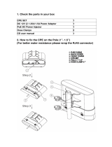
2.1.1 Package Content...................................................................................................8
2.1.2 Additional Installation Requirements.................................................................... 8
2.1.3 Guidelines for Positioning the ODU ......................................................................9
2.1.4 IDU-ODU Cables ....................................................................................................9
2.2 Pole Mounting the ODU ......................................................................................11
2.2.1 Pole Mounting the ODU ......................................................................................11
2.3 Connecting the ODU Cables ................................................................................13
2.3.1 The PRO 6000 CPE Connectors ........................................................................... 13
2.3.2 Connecting the Grounding Cable ........................................................................ 14
2.3.3 Connecting and Sealing the IDU-ODU PoE Cable ................................................ 14
2.3.4 Installing the Power Injector IDU ........................................................................ 16
2.4 Checking for Proper Operation ...........................................................................19
Chapter 3 - Commissioning .................................................................................. 21
3.1 Introduction.......................................................................................................22
3.2 Configuring the Unit Using the Web Management Interface.................................23
3.2.1 Accessing the Web Management Interface ........................................................ 23

Contents
3.2.2 Applying Changes and Using Help....................................................................... 25
3.3 Configuring the Unit Using the WiMAX Modem Application CD.............................26
3.4 Configuring the CPE Using the IPKG Upgrade .......................................................30
3.5 Creating a Default Configuration File..................................................................31
3.6 Operation Verification........................................................................................34
Chapter 4 - Configuring Setup Parameters ........................................................... 35
4.1 Introduction.......................................................................................................36
4.2 Setting Basic Parameters....................................................................................37
4.3 Setting Password ...............................................................................................40
4.4 Setting Device Time Zone ...................................................................................41
4.5 Setting Device Name ..........................................................................................42
4.6 Restore to Factory Default Configuration ...........................................................43
Chapter 5 - Configuring Local Address Parameters ............................................... 44
5.1 Introduction.......................................................................................................45
5.2 DHCP Server .......................................................................................................46
5.3 Lease Status ......................................................................................................47
5.4 Lease Reservation ..............................................................................................48
Chapter 6 - Setting Advanced Parameters ............................................................ 49
6.1 Introduction.......................................................................................................50
6.2 Authentication ...................................................................................................51
6.3 Security .............................................................................................................53
6.4 Firewall ..............................................................................................................55
6.5 MAC Filter ..........................................................................................................57
6.6 IP Filter ..............................................................................................................58
6.7 Port Forwarding/Trigger......................................................................................59
6.7.1 Port Forwarding .................................................................................................. 59

Contents
6.7.2 Port Trigger......................................................................................................... 60
6.8 Dynamic DNS .....................................................................................................62
Chapter 7 - Displaying Status Details................................................................... 63
7.1 Introduction.......................................................................................................64
7.2 Device Status .....................................................................................................65
7.3 WiMAX Status ....................................................................................................67
7.4 Software Status .................................................................................................72
7.5 Telephony Status ...............................................................................................73
7.6 Certificate Status...............................................................................................74
7.7 About ................................................................................................................76
Chapter 8 - Configuring Telephony Parameters .................................................... 77
8.1 Introduction.......................................................................................................78
8.2 VoIP Parameters.................................................................................................79
Chapter 9 - Engineering ....................................................................................... 81
9.1 Introduction.......................................................................................................82
9.2 WiMAX Configuration .........................................................................................83
9.3 VoIP Configuration .............................................................................................87
9.4 Service Line........................................................................................................96
9.5 Device Configuration ........................................................................................100
9.6 DM (Device Management) Settings ...................................................................101
9.6.1 TR-069 .............................................................................................................. 101
9.6.2 OMA Device Management Parameters.............................................................. 102
9.7 Function Settings .............................................................................................106
9.8 UI Settings .......................................................................................................107

Figures
Figures
Figure 1-1: BreezeMAX PRO 6000................................................................................................... 2
Figure 2-1: Mounting the ODU on the Pole .................................................................................. 11
Figure 2-2: ODU Pole Installation Using the Tilt Accessory, Vertical Polarization......................... 12
Figure 2-3: CPE Connections ......................................................................................................... 13
Figure 2-4: Rear View of the ODU ................................................................................................14
Figure 2-5: Ethernet Connector Pin Assignments ......................................................................... 15
Figure 2-6: Inserting the Cable into the Sealing Cap .................................................................... 15
Figure 2-7: Sealing Gland Fastening Tool...................................................................................... 16
Figure 2-8: Cold Shrink Tubing...................................................................................................... 16
Figure 2-9: IDU-ODU PoE port (“TO/FROM ODU PoE (RJ45)”) ....................................................... 17
Figure 2-10: Data Equipment and Telephone Ports...................................................................... 18
Figure 2-11: LEDs.......................................................................................................................... 20
Figure 3-1: Login Window ............................................................................................................. 23
Figure 3-2: Main Window (Device Status)..................................................................................... 24
Figure 3-3: Installation Setup Wizard Window.............................................................................. 26
Figure 3-4: Choose Your ISP Window............................................................................................ 27
Figure 3-5: Ready To Install Window ............................................................................................ 27
Figure 3-6: Installing Window ....................................................................................................... 28
Figure 3-7: Installation Succeeded ............................................................................................... 28
Figure 3-8: Installation Complete ................................................................................................. 29
Figure 3-9: Status - Software Page ..............................................................................................30
Figure 3-10: Engineering - Dev Config Page ................................................................................. 31
Figure 3-11: Generate IPKG Tool .................................................................................................. 32
Figure 3-12: Generation Results ................................................................................................... 33
Figure 4-1: Setup - Basic Parameters ........................................................................................... 37
Figure 4-2: Setup - Password ....................................................................................................... 40
Figure 4-3: Setup - Device Time.................................................................................................... 41

Figures
Figure 4-4: Setup - Device Name .................................................................................................. 42
Figure 4-5: Setup - Restore to Factory Warning........................................................................... 43
Figure 5-1: DHCP Server................................................................................................................ 46
Figure 5-2: Lease Status ............................................................................................................... 47
Figure 5-3: Lease Reservation ...................................................................................................... 48
Figure 6-1: Advanced - Authentication......................................................................................... 51
Figure 6-2: Advanced - Security.................................................................................................... 53
Figure 6-3: Advance - Firewall ......................................................................................................55
Figure 6-4: Advance - MAC Filter .................................................................................................. 57
Figure 6-5: Advance - IP Filter.......................................................................................................58
Figure 6-6: Advance - Port Forwarding ......................................................................................... 59
Figure 6-7: Advance - Port Trigger................................................................................................60
Figure 6-8: Advanced - Dynamic DNS ........................................................................................... 62
Figure 7-1: Status - Device Status ................................................................................................ 65
Figure 7-2: Status - WiMAX Status ...............................................................................................67
Figure 7-3: Status - Software .......................................................................................................72
Figure 7-4: Status - Telephony Status .......................................................................................... 73
Figure 7-5: Status - Certificate ..................................................................................................... 74
Figure 7-6: Status - About ............................................................................................................76
Figure 8-1: Telephony - VoIP Parameters ..................................................................................... 79
Figure 9-1: Engineering - WMAX Config. ....................................................................................... 83
Figure 9-2: Engineering - VoIP ......................................................................................................87
Figure 9-3: Engineering - VoIP (continued)................................................................................... 88
Figure 9-4: Engineering - Service Line (ETHCS and IP-CS) ............................................................. 97
Figure 9-5: Engineering - DEV Config. ......................................................................................... 100
Figure 9-6: Engineering - DM Settings (TR-069) ......................................................................... 101
Figure 9-7: Engineering - DM Settings (OMA) ............................................................................. 103
Figure 9-8: Engineering - Function Settings ............................................................................... 106
Figure 9-9: Engineering - UI Settings .......................................................................................... 107

Tables
Tables
Table 1-1: PRO 6000 CPE General Specifications............................................................................ 3
Table 1-2: PRO 6000 CPE WiMAX Radio Specifications ................................................................... 3
Table 1-3: PRO 6000 CPE Power Specification................................................................................ 5
Table 1-4: PRO 6000 CPE Environmental Specifications .................................................................5
Table 1-5: PRO 6000 CPE Regulatory Specifications....................................................................... 5
Table 1-6: PRO 6000 CPE Reliability Specifications.........................................................................6
Table 2-1: Approved Category 5E Ethernet Cables .......................................................................10
Table 2-2: LED Functionality ......................................................................................................... 19
Table 3-1: Basic Parameters .........................................................................................................22
Table 4-1: Basic Parameters .........................................................................................................37
Table 7-1: Device Status Parameters............................................................................................ 65
Table 7-2: WiMAX System Parameters.......................................................................................... 68
Table 9-1: WMAX Config. Settings ................................................................................................84
Table 9-2: VoIP Settings................................................................................................................89
Table 9-3: Service Line Parameters............................................................................................... 98
Table 9-4: DM Settings - TR-069................................................................................................. 101
Table 9-5: DM Settings - OMA .................................................................................................... 103
Table 9-6: Function Settings....................................................................................................... 106
Table 9-7: UI Settings Parameters .............................................................................................. 107


BreezeMAX PRO 6000 Product Manual
Chapter 1 - Product DescriptionIntroducing the BreezeMAX PRO 6000
Chapter 1 - Product Description Introducing the BreezeMAX PRO 6000
2
1.1 Introducing the BreezeMAX PRO 6000
The PRO 6000 CPE comprises an Outdoor Unit (ODU) and an Indoor Unit (IDU).
The ODU includes the modem, radio, data processing, management and voice gateway components of
the Subscriber Unit (SU). It also includes an integral high-gain flat antenna. The ODU connects to the IDU
and to the user's equipment through a 10/100 BaseT Ethernet port.
The IDU is powered from the mains and connects to the ODU via a Category 5E Ethernet cable carrying
the Ethernet data between the two units, as well as power (56 VDC) and control signals to the ODU and
status indications from the ODU.
Figure 1-1: BreezeMAX PRO 6000
ODU
IDU

BreezeMAX PRO 6000 Product Manual
Chapter 1 - Product DescriptionBreezeMAX PRO 6000 CPE Specifications
Chapter 1 - Product Description BreezeMAX PRO 6000 CPE Specifications
3
1.2 BreezeMAX PRO 6000 CPE Specifications
1.2.1 General
1.2.2 WiMAX Radio
Table 1-1: PRO 6000 CPE General Specifications
Feature Description
Flash ROM 32MB
Ethernet LAN port One RJ-45 port
10/100 auto-sensing, auto-MDX
Channel Step Size In 250 kHz steps
POTS One RJ-11
Power supply Input: Universal range 100~240VAC
Output: 56 VDC
Frequency: 50Hz to 60Hz
Current: 0.8A
WiMAX SoC BCS5350 and Dual Core 300MHz
RF IC BCSR-200 / Dual Band 1T/2R RFIC
RAM 64MB
Table 1-2: PRO 6000 CPE WiMAX Radio Specifications
Item Description
Radio Type IEEE 802.16e 2005 WAVE 2
Frequency Band 3.3 - 3.7 GHz
(range will be increased to 3.3 - 3.8 GHz in future release)
Antenna Type Two WiMAX antennas
Channel Bandwidth 5.00, 7.00, and 10.00 MHz
Modulation Technique Scaleable OFDMA employing Time-Division Duplex (TDD)
mechanism
PRBS subcarrier randomization
Contains pilot, preamble, and ranging modulation

BreezeMAX PRO 6000 Product Manual
Chapter 1 - Product DescriptionBreezeMAX PRO 6000 CPE Specifications
Chapter 1 - Product Description BreezeMAX PRO 6000 CPE Specifications
4
FEC Coding Rates Up Link and Down Link: QPSK, 16 QAM, 64 QAM
QPSK and 16QAM - 1/2 and 3/4
64QAM - 1/2, 2/3, 3/4, 5/6
TPL (Transmit Power Level) 27 dBm typical (maximum)
Channel Step Size In 250 kHz steps
Synchronization Referenced to the WiMAX BTS Timing Module
Frequency Accuracy MRCT Compliant
Air Interface IEEE 802.16e Wireless MAN-OFDMA
TDD Duty Cycle (Tx/Rx) Rx up to 75% , Tx up to 50%
SISO or MIMO MIMO (1TX, 2RX)
Regulatory Compliance FCC parts 15, 25, 27, 90
RSS 192, 197
Frame Duration 5 msec.
RF Transmitter Specifications
RF dynamic range 45dB minimum
Transmit Power Control Relative
Accuracy
mRCT compliant
Transmit and Receive Switching Gap 50 S
RF Receiver Specifications
Impedance 50 ohms nominal
Input return loss 10dBi
RX Sensitivity Typical 3dB better than mRCT in SISO mode, and 6 dB better
in MRC or MIMO mode. -94.5 dBm maximum.
Adjacent Channel Rejection 4 dB min.
Receive signal 64QAM-3/4, 3dB above sensitivity level.
Non-Adjacent Channel Rejection 23 dB min
Receive signal 64QAM-3/4, 3dB above sensitivity level.
Antenna Specifications
Antenna Gain Typical 15 dBi
Antenna Connectors None. Embedded IPEX
Table 1-2: PRO 6000 CPE WiMAX Radio Specifications
Item Description

BreezeMAX PRO 6000 Product Manual
Chapter 1 - Product DescriptionBreezeMAX PRO 6000 CPE Specifications
Chapter 1 - Product Description BreezeMAX PRO 6000 CPE Specifications
5
1.2.3 Power Specification
1.2.4 Environmental Specifications
1.2.5 Regulatory Specifications
Standards for all frequency bands:
Table 1-3: PRO 6000 CPE Power Specification
Item Details
Power Consumptions Outdoor CPE: 16W Maximum
Power Adapter Input of 100 VAC - 240 VAC 50 Hz to 60 Hz
Power over Ethernet 56 VDC
Table 1-4: PRO 6000 CPE Environmental Specifications
Item Details
Operating Temperature -40°C ~ 60°C
Storage Temperature -40°C ~ 70°C
Operating and Storage Humidity 5% - 95%
Table 1-5: PRO 6000 CPE Regulatory Specifications
Standard Specification Applicable to
FCC Part 15 ODU
Part 90, Subpart Z
ETSI ETSI EN 302 326 ODU
WiMAX IEEE-802.16-2005. ODU
Environmental ETSI 300 019-2-4 Class T4.1E ODU
ETSI 300 019-2-3 Class T3.2. PoE (+PS)
Transportation & Storage ETSI 300 019-2-2 Class T2.3.
ETSI 300 019-2-1 Class T1.2.
System
EU EMC ETSI EN 301 489-1/4 System
US EMC FCC part 15 Subpart B (Emission test) System
Immunity Surge (Lightning protection), ITU-T K.21 System
/