Page is loading ...

Installation Instructions
Original Instructions
ArmorStratix 5700 Ethernet Managed Switches
Catalog Numbers 1783-ZMS8TA, 1783-ZMS16TA, 1783-ZMS24TA, 1783-ZMS4T4E2TGP, 1783-ZMS4T4E2TGN, 1783-ZMS8T8E2TGP,
1783-ZMS8T8E2TGN
Topic Page
Parts List 4
Required Tools 4
Site Requirements 4
Mount the Switch 5
Ground the Switch 5
Connect the Switch to a DC Power Source 6
Wire External Alarms 7
Install or Remove the SD Card 8
Connect to 10/100 and 100/1000 Ports 8
Remove Power from a Switch with PoE 9
Confirm Installation 10
Specifications 10
Additional Resources 11

2 Rockwell Automation Publication 1783-IN017A-EN-P - July 2017
ArmorStratix 5700 Ethernet Managed Switches
ATTENTION: Read this document and the documents listed in the Additional Resources section about installation, configuration and operation of this equipment before you install, configure, operate or
maintain this product. Users are required to familiarize themselves with installation and wiring instructions in addition to requirements of all applicable codes, laws, and standards.
Activities including installation, adjustments, putting into service, use, assembly, disassembly, and maintenance are required to be carried out by suitably trained personnel in accordance with applicable code
of practice.
If this equipment is used in a manner not specified by the manufacturer, the protection provided by the equipment may be impaired.
⌘˖൘ᆹ㻵ǃ䝽㖞ǃ઼㔤ᣔᵜӗ૱ࡽˈ䈧䰵䈫ᵜ᮷ẓԕ৺ Ā ަԆ䍴Ⓚ ā 䜘࠶ࡇࠪⲴᴹޣ䇮༷ᆹ㻵ǃ䝽㖞઼Ⲵᓄ᮷ẓDŽ䲔Ҷᡰᴹ䘲⭘㿴㤳ǃ⌅
ᖻ઼ḷ߶Ⲵޣ㾱≲ѻཆˈ⭘ᡧ䘈ᗵ享⟏ᚹᆹ㻵઼᧕㓯䈤᰾DŽ
ᆹ㻵ǃ䈳ᮤǃᣅ䘀ǃ֯⭘ǃ㓴㻵ǃন઼㔤ᣔㅹ亩ᗵ享⭡㓿䗷䘲ᖃ䇝㓳ⲴуъӪઈ᤹➗䘲⭘Ⲵ㿴㤳ᇎᯭDŽ
ྲ᷌ᵚ᤹➗ࡦ䙐୶ᤷᇊⲴᯩᔿ֯⭘䈕䇮༷ˈࡉਟ㜭Պᦏᇣ䇮༷ᨀⲴ؍ᣔDŽ
ATENCIÓN: Antes de instalar, configurar, poner en funcionamiento o realizar el mantenimiento de este producto, lea este documento y los documentos listados en la sección Recursos adicionales acerca de la
instalación, configuración y operación de este equipo. Los usuarios deben familiarizarse con las instrucciones de instalación y cableado y con los requisitos de todos los códigos, leyes y estándares vigentes.
El personal debidamente capacitado debe realizar las actividades relacionadas a la instalación, ajustes, puesta en servicio, uso, ensamblaje, desensamblaje y mantenimiento de conformidad con el código de
práctica aplicable.
Si este equipo se usa de una manera no especificada por el fabricante, la protección provista por el equipo puede resultar afectada.
ATENÇÃO: Leia este e os demais documentos sobre instalação, configuração e operação do equipamento que estão na seção Recursos adicionais antes de instalar, configurar, operar ou manter este produto. Os
usuários devem se familiarizar com as instruções de instalação e fiação além das especificações para todos os códigos, leis e normas aplicáveis.
É necessário que as atividades, incluindo instalação, ajustes, colocação em serviço, utilização, montagem, desmontagem e manutenção sejam realizadas por pessoal qualificado e especializado, de acordo com o
código de prática aplicável.
Caso este equipamento seja utilizado de maneira não estabelecida pelo fabricante, a proteção fornecida pelo equipamento pode ficar prejudicada.
ВНИМАНИЕ: Перед тем как устанавливать, настраивать, эксплуатировать или обслуживать данное оборудование, прочитайте этот документ и документы, перечисленные в разделе
«Дополнительные ресурсы». В этих документах изложены сведения об установке, настройке и эксплуатации данного оборудования. Пользователи обязаны ознакомиться с инструкциями по
установке и прокладке соединений, а также с требованиями всех применимых норм, законов и стандартов.
Все действия, включая установку, наладку, ввод в эксплуатацию, использование, сборку, разборку и техническое обслуживание, должны выполняться обученным персоналом в соответствии с
применимыми нормами и правилами.
Если оборудование используется не предусмотренным производителем образом, защита оборудования может быть нарушена.
ὀព ᮏ〇ရࢆタ⨨ࠊᵓᡂࠊ✌ືࡲࡓࡣಖᏲࡍࡿ๓ࠊᮏ᭩࠾ࡼࡧᮏᶵჾࡢタ⨨ࠊタᐃࠊ᧯సࡘ࠸࡚ࡢཧ⪃㈨ᩱࡢヱᙜ⟠ᡤグ㍕ࡉࢀ࡚࠸ࡿᩥ᭩┠
ࢆ㏻ࡋ࡚ࡃࡔࡉ࠸ࠋ࣮ࣘࢨࡣࠊࡍ࡚ࡢヱᙜࡍࡿ᮲ࠊἲᚊࠊつ᱁ࡢせ௳ຍ࠼࡚ࠊタ⨨࠾ࡼࡧ㓄⥺ࡢᡭ㡰⩦⇍ࡋ࡚࠸ࡿᚲせࡀ࠶ࡾࡲࡍࠋ
タ⨨ㄪᩚࠊ㐠㌿ࡢ㛤ጞࠊ⏝ࠊ⤌❧࡚ࠊゎయࠊಖᏲࢆྵࡴㅖసᴗࡣࠊヱᙜࡍࡿᐇつ๎ᚑࡗ࡚カ⦎ࢆཷࡅࡓ㐺ษ࡞సᴗဨࡀᐇ⾜ࡍࡿᚲせࡀ࠶ࡾࡲࡍࠋ
ᮏᶵჾࡀ〇㐀࣓࣮࢝ࡼࡾᣦᐃࡉࢀ࡚࠸࡞࠸᪉ἲ࡛⏝ࡉࢀ࡚࠸ࡿሙྜࠊᶵჾࡼࡾᥦ౪ࡉࢀ࡚࠸ࡿಖㆤࡀᦆ࡞ࢃࢀࡿᜍࢀࡀ࠶ࡾࡲࡍࠋ
ACHTUNG: Lesen Sie dieses Dokument und die im Abschnitt „Weitere Informationen“aufgeführten Dokumente, die Informationen zu Installation, Konfiguration und Bedienung dieses Produkts enthalten,
bevor Sie dieses Produkt installieren, konfigurieren, bedienen oder warten. Anwender müssen sich neben den Bestimmungen aller anwendbaren Vorschriften, Gesetze und Normen zusätzlich mit den
Installations- und Verdrahtungsanweisungen vertraut machen.
Arbeiten im Rahmen der Installation, Anpassung, Inbetriebnahme, Verwendung, Montage, Demontage oder Instandhaltung dürfen nur durch ausreichend geschulte Mitarbeiter und in Übereinstimmung mit
den anwendbaren Ausführungsvorschriften vorgenommen werden.
Wenn das Gerät in einer Weise verwendet wird, die vom Hersteller nicht vorgesehen ist, kann die Schutzfunktion beeinträchtigt sein.
ATTENTION : Lisez ce document et les documents listés dans la section Ressources complémentaires relatifs à l’installation, la configuration et le fonctionnement de cet équipement avant d’installer,
configurer, utiliser ou entretenir ce produit. Les utilisateurs doivent se familiariser avec les instructions d’installation et de câblage en plus des exigences relatives aux codes, lois et normes en vigueur.
Les activités relatives à l’installation, le réglage, la mise en service, l’utilisation, l’assemblage, le démontage et l’entretien doivent être réalisées par des personnes formées selon le code de pratique en vigueur.
Si cet équipement est utilisé d’une façon qui n’a pas été définie par le fabricant, la protection fournie par l’équipement peut être compromise.
㭒㦮 a ⽎G㩲䛞G㍺䂮 SG㍺㩫 SG㧧☯G⡦⓪G㥶㰖G⽊㑮䞮₆G㩚㠦G⽎Gⶎ㍲⯒G䙂䞾䞮㡂G㍺䂮 SG㍺㩫GG㧧☯㠦Gὖ䞲G㺎ἶG㧦⬢G㎏㎮㦮Gⶎ㍲✺㦚G✲㔲G㧓ἶG㑯㰖䞮
㕃㔲㡺 UG㌂㣿㧦⓪G⳾✶Gὖ⩾G′㩫 SG⻫′GG䚲㭖㠦㍲G㣪ῂ䞮⓪G㌂䟃㠦G╖䟊G✲㔲G㍺䂮GG⺆㍶G㰖䂾㦚G㑯㰖䟊㟒G䞿┞┺ U
㍺䂮 SG㫆㩫 SGṖ☯ SG㌂㣿 SG㫆Ⱃ SG䟊 SG㥶㰖⽊㑮G❇G⳾✶G㧧㠛㦖Gὖ⩾G′㩫㠦G➆⧒G㩗㩞䞲Gᾦ㥷㦚G㦖G㌂㣿㧦⯒G䐋䟊㍲ⰢG㑮䟟䟊㟒G䞿┞┺ U
⽎G㧻゚⯒G㩲㫆㌂ṖGⳛ㔲䞮㰖G㞠㦖G⻫㦒⪲G㌂㣿䞮ⳊG㧻゚㦮G⽊䢎G₆⓻㧊G㏦㌗♶G㑮G㧞㔋┞┺ U
ATTENZIONE Prima di installare, configurare ed utilizzare il prodotto, o effettuare interventi di manutenzione su di esso, leggere il presente documento ed i documenti elencati nella sezione “Altre risorse”,
riguardanti l’installazione, la configurazione ed il funzionamento dell’apparecchiatura. Gli utenti devono leggere e comprendere le istruzioni di installazione e cablaggio, oltre ai requisiti previsti dalle leggi,
codici e standard applicabili.
Le attività come installazione, regolazioni, utilizzo, assemblaggio, disassemblaggio e manutenzione devono essere svolte da personale adeguatamente addestrato, nel rispetto delle procedure previste.
Qualora l’apparecchio venga utilizzato con modalità diverse da quanto previsto dal produttore, la sua funzione di protezione potrebbe venire compromessa.
DİKKAT: Bu ürünün kurulumu, yapılandırılması, işletilmesi veya bakımı öncesinde bu dokümanı ve bu ekipmanın kurulumu, yapılandırılması ve işletimi ile ilgili İlave Kaynaklar bölümünde yer listelenmiş
dokümanları okuyun. Kullanıcılar yürürlükteki tüm yönetmelikler, yasalar ve standartların gereksinimlerine ek olarak kurulum ve kablolama talimatlarını da öğrenmek zorundadır.
Kurulum, ayarlama, hizmete alma, kullanma, parçaları birleştirme, parçaları sökme ve bakım gibi aktiviteler sadece uygun eğitimleri almış kişiler tarafından yürürlükteki uygulama yönetmeliklerine uygun
şekilde yapılabilir.
Bu ekipman üretici tarafından belirlenmiş amacın dışında kullanılırsa, ekipman tarafından sağlanan koruma bozulabilir.
⌘һ丵˖൘ᆹ㼍ǃ䁝ᇊǃᡆ㏝䆧ᵜ⭒૱ࡽˈ䃻ݸ䯡䆰↔᮷Ԧԕ৺ࡇᯬ NjަԆ䋷Ⓚnjㄐㇰѝᴹ䰌ᆹ㼍ǃ䁝ᇊ㠷↔䁝ۉⲴ᮷ԦDŽ֯⭘㘵ᗵ丸⟏ᚹᆹ㼍
઼䝽㐊ᤷ⽪ˈіㅖਸᡰᴹ⌅㾿ǃ⌅ᖻ઼⁉Ⓠ㾱≲DŽ
वᤜᆹ㼍ǃ䃯ᮤǃӔԈ֯⭘ǃ֯⭘ǃ㍴㼍ǃন઼㏝䆧ㅹअ䜭ᗵ丸Ӕ⭡ᐢ㏃䙾䚙⮦䁃㐤ⲴӪ䙢㹼ˈԕㅖਸ䚙⭘Ⲵሖ⌅㾿DŽ
ྲ᷌ሷ䁝ۉ⭘ᯬ䶎㼭䙐୶ᤷᇊⲴ⭘䙄ᱲˈਟ㜭ᴳ䙐ᡀ䁝ۉᡰᨀⲴ؍䆧࣏㜭ਇᨽDŽ
POZOR: Než začnete instalovat, konfigurovat či provozovat tento výrobek nebo provádět jeho údržbu, přečtěte si tento dokument a dokumenty uvedené v části Dodatečné zdroje ohledně instalace, konfigurace
a provozu tohoto zařízení. Uživatelé se musejí vedle požadavků všech relevantních vyhlášek, zákonů a norem nutně seznámit také s pokyny pro instalaci a elektrické zapojení.
Činnosti zahrnující instalaci, nastavení, uvedení do provozu, užívání, montáž, demontáž a údržbu musí vykonávat vhodně proškolený personál v souladu s příslušnými prováděcími předpisy.
Pokud se toto zařízení používá způsobem neodpovídajícím specifikaci výrobce, může být narušena ochrana, kterou toto zařízení poskytuje.
UWAGA: Przed instalacją, konfiguracją, użytkowaniem lub konserwacją tego produktu należy przeczytać niniejszy dokument oraz wszystkie dokumenty wymienione w sekcji Dodatkowe źródła omawiające
instalację, konfigurację i procedury użytkowania tego urządzenia. Użytkownicy mają obowiązek zapoznać się z instrukcjami dotyczącymi instalacji oraz oprzewodowania, jak również z obowiązującymi
kodeksami, prawem i normami.
Działania obejmujące instalację, regulację, przekazanie do użytkowania, użytkowanie, montaż, demontaż oraz konserwację muszą być wykonywane przez odpowiednio przeszkolony personel zgodnie z
obowiązującym kodeksem postępowania.
Jeśli urządzenie jest użytkowane w sposób inny niż określony przez producenta, zabezpieczenie zapewniane przez urządzenie może zostać ograniczone.
OBS! Läs detta dokument samt dokumentet, som står listat i avsnittet Övriga resurser, om installation, konfigurering och drift av denna utrustning innan du installerar, konfigurerar eller börjar använda eller
utföra underhållsarbete på produkten. Användare måste bekanta sig med instruktioner för installation och kabeldragning, förutom krav enligt gällande koder, lagar och standarder.
Åtgärder som installation, justering, service, användning, montering, demontering och underhållsarbete måste utföras av personal med lämplig utbildning enligt lämpligt bruk.
Om denna utrustning används på ett sätt som inte anges av tillverkaren kan det hända att utrustningens skyddsanordningar försätts ur funktion.
LET OP: Lees dit document en de documenten die genoemd worden in de paragraaf Aanvullende informatie over de installatie, configuratie en bediening van deze apparatuur voordat u dit product installeert,
configureert, bediend of onderhoudt. Gebruikers moeten zich vertrouwd maken met de installatie en de bedradingsinstructies, naast de vereisten van alle toepasselijke regels, wetten en normen.
Activiteiten zoals het installeren, afstellen, in gebruik stellen, gebruiken, monteren, demonteren en het uitvoeren van onderhoud mogen uitsluitend worden uitgevoerd door hiervoor opgeleid personeel en in
overeenstemming met de geldende praktijkregels.
Indien de apparatuur wordt gebruikt op een wijze die niet is gespecificeerd door de fabrikant, dan bestaat het gevaar dat de beveiliging van de apparatuur niet goed werkt.

Rockwell Automation Publication 1783-IN017A-EN-P - July 2017 3
ArmorStratix 5700 Ethernet Managed Switches
Environment and Enclosure
ATTENTION: This equipment is intended for use in overvoltage Category II applications (as defined in IEC 60664-1), at altitudes up to 2000 m (6562 ft) without
derating.
This equipment is not intended for use in residential environments and may not provide adequate protection to radio communication services in such
environments.
This equipment is supplied as enclosed equipment. It should not require additional system enclosure when used in locations consistent with the equipment
Enclosure Type Ratings. Subsequent sections of this publication may contain more information regarding specific enclosure type ratings, beyond what this
product provides, that are required to comply with certain product safety certifications.
In addition to this publication, see the following:
• Industrial Automation Wiring and Grounding Guidelines, publication
1770-4.1, for more installation requirements
• NEMA Standard 250 and IEC 60529, as applicable, for explanations of the degrees of protection provided by enclosures
Class A Notice for Taiwan and other Traditional Chinese Markets
ATTENTION: This is a Class A Information Product. When used in a residential environment, it may cause radio frequency interference. Under such circumstances,
the user may be requested to take appropriate countermeasures.
Prevent Electrostatic Discharge
ATTENTION: This equipment is sensitive to electrostatic discharge, which can cause internal damage and affect normal operation. Follow these guidelines when
you handle this equipment:
• Touch a grounded object to discharge potential static.
• Wear an approved grounding wriststrap.
• Do not touch connectors or pins on component boards.
• Do not touch circuit components inside the equipment.
• Use a static-safe workstation, if available.
• Store the equipment in appropriate static-safe packaging when not in use.
ATTENTION: Make sure all connectors and caps are securely tightened to properly seal the connections against leaks and maintain IP enclosure type
requirements.
ATTENTION: The console ports are intended for temporary local programming purposes only and not intended for permanent connection. The console port
cables are not to exceed 3.0 m (9.84 ft) and must not contain hubs.
ATTENTION: This equipment is certified for use only within the surrounding air temperature range of 0…60 °C (32…140 °F). The equipment must not be used
outside of this range.
ATTENTION: Use only a soft dry anti-static cloth to wipe down equipment. Do not use any cleaning agents.

4 Rockwell Automation Publication 1783-IN017A-EN-P - July 2017
ArmorStratix 5700 Ethernet Managed Switches
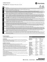
Parts List
Verify that you have these items.
Required Tools
Obtain these tools:
• An IP67-rated cordset or patchcord with a female-end, 4-pin mini connector to provide 24V DC power to the switch
• Ratcheting torque screwdriver that exerts up to 1.69 N
•m (15 in•lbs) of pressure
• #6 ring terminal lug for 5.3 mm
(10 AWG) wire, such as Thomas & Bett part number 10RC6 or equivalent
• Crimping tool, such as Thomas & Bett part number WT2000, ERG-2001, or equivalent
• 5.3 mm
2
(10 AWG) copper ground wire, such as Belden part number 9912 or equivalent
• Wire-stripping tool
• For panel-mounting without a DIN rail, M5 or #10-24 or #10-32 bolts or screws with 1.27 cm (0.5 in.) O.D. flat washers
For simplified cabling, the automatic medium-dependent interface crossover (auto-MDIX) feature is enabled by default on the switch. With
auto-MDIX enabled, the switch detects the required cable type for copper Ethernet connections and configures the interfaces accordingly. You can
use either a crossover or a straight-through cable for connections to a 10/100 or 10/100/1000 Ethernet switch port, regardless of the type of device
on the other end of the connection.
Site Requirements
Observe these site requirements:
• Clearance to front and rear panels meets these conditions:
– Front-panel status indicators can be easily read.
– Access to ports is sufficient for unrestricted cabling.
– Front-panel DC power connectors and the alarm relay connector are within reach of the connection to the DC power source.
• To prevent the switch from overheating, observe the following minimum clearances:
– Top and bottom: 50.8 mm (2.0 in.)
– Sides: 50.8 mm (2.0 in.)
– Front: 50.8 mm (2.0 in.)
• Temperature surrounding the unit does not exceed 60 °C (140 °F).
• For 10/100 ports and 10/100/1000 ports, the cable length from a switch to an attached device cannot exceed 100 m (328 ft).
• For maximum noise immunity, X-code shielded cables must be used on M12 uplink ports. For recommended M12 media, refer to
http://ab.rockwellautomation.com/Connection-Devices/EtherNet-Media.
• Cabling is away from sources of electrical noise, such as radios, power lines, and fluorescent lighting fixtures.
• Connect the unit to only an IP67-rated power supply. Rockwell Automation offers a Bulletin 1607 IP67-rated power supply to provide
24V DC power to the switch.
1 ArmorStratix™ 5700 switch
2 Documentation
At the end of its life, this equipment should be collected separately from any unsorted municipal waste.
1
2

Rockwell Automation Publication 1783-IN017A-EN-P - July 2017 5
ArmorStratix 5700 Ethernet Managed Switches
Mount the Switch
To mount the switch, follow these steps.
1. Position the rear panel of the switch against the wall or a panel in the desired location.
2. Place a number-10 screw that you provide through each mounting ear, and screw them into the wall.
Ground the Switch
Use at least 4 mm
2
(12 AWG) wire to connect to the external grounding screw.
The ground lug is not supplied with the switch. You can use one of these options:
• Single ring terminal
• Two single ring terminals
To ground the switch to earth ground, follow these steps. Be sure to follow any grounding requirements at your site.
1. Use a Phillips screwdriver or a ratcheting torque screwdriver with a Phillips head to remove the ground screw from the front panel of the
switch.
Store the ground screw for later use.
2. Use the guidelines from the manufacturer to determine the wire length to be stripped.
3. Insert the ground wire into the ring terminal lug and use a crimping tool to crimp the terminal to the wire.
If you are using two ring terminals, repeat this action for the second ring terminal.
4. Slide the ground screw through the terminal.
ATTENTION: To prevent bodily injury when mounting or servicing this unit in a rack, you must take special precautions to ensure that the system remains stable.
The following guidelines are provided to ensure your safety:
• This unit should be mounted at the bottom of the rack if it is the only unit in the rack.
• When mounting this unit in a partially filled rack, load the rack from the bottom to the top with the heaviest component at the bottom of the rack.
• If the rack is provided with stabilizing devices, install the stabilizers before mounting or servicing the unit in the rack.
ATTENTION: To make sure that the equipment is reliably connected to earth ground, follow the grounding procedure instructions and use a suitable ring
terminal lug, such as Thomas & Bett part number 10RCR or equivalent.
32477
32273-M

6 Rockwell Automation Publication 1783-IN017A-EN-P - July 2017
ArmorStratix 5700 Ethernet Managed Switches
5. Insert the ground screw into the functional ground screw opening on the front panel.
6. Use a ratcheting torque screwdriver to tighten the ground screws and ring terminal lugs to the switch front panel to 0.4 N
m (3.5 lbin).
Do not exceed the recommended torque.
7. Attach the other end of the ground wire to a grounded bare metal surface, such as a ground bus, a grounded DIN rail, or a grounded bare
rack.
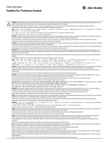
Connect the Switch to a DC Power Source
You must supply a power solution for the device. Use an IP67-rated cordset or patchcord with a female-end, M12 4-pin mini-connector. Rockwell
Automation offers a Bulletin 1607 IP67-rated power supply to provide 24V DC power to the switch. Ethernet communication and control power
cables are available separately. Connect the DC power to the switch through the front panel connector.
M12 4-pin Mini-connector
Power Connector Pinout
ATTENTION: If multiple power sources are used, do not exceed the specified isolation voltage.
ATTENTION: To comply with the CE Low Voltage Directive (LVD), all power sources to this equipment must be powered from a source compliant with the
following: Safety Extra Low Voltage (SELV) or Protected Extra Low Voltage (PELV).
ATTENTION: To comply with UL restrictions, all power sources to this equipment must be powered from a source compliant with the following:
Class 2 or Limited Voltage/Current.
32545
32478
1 DC_B+
2 DC_A+
3 DC_A-
4 DC_B-

Rockwell Automation Publication 1783-IN017A-EN-P - July 2017 7
ArmorStratix 5700 Ethernet Managed Switches
Power over Ethernet
For switches with Power over Ethernet (PoE) capability, PoE power is drawn from the single power connection. There is no separate power input for
PoE.
Cordsets
Patchcords
Wire External Alarms
Some switch models have the following for external alarms:
• One input alarm relay circuit to sense whether the alarm input is open or closed relative to the alarm input reference pin.
• One output alarm relay circuit with one Form C (single-pole, double-throw) relay with one normally open (NO) and one normally closed
(NC) contact. You can configure the output alarm as either normally energized or normally de-energized by using the CLI.
Alarm signals are connected to the switch through the 6-way alarm relay connector. Three connections are dedicated to the alarm input.
An alarm input and the reference ground wiring connection are required to complete one input alarm circuit. You must provide either an NO or an
NC dry contact to complete the alarm circuit between reference ground and the alarm input.
The three remaining connections for the Form C output alarm circuit are as follows:
• NO output
• NC output
• common
An alarm output and the common wiring connection are required to complete one output alarm circuit. The Form C output alarm relay provides
one NO and one NC dry contact.
Use M12 A-coded cable to connect to the alarm connector on the switch. Recommended torque is 0.5…0.8 N•m (4.43…7.08 lb•in. The
recommended cable part number from Molex is 1200650523. One end of the cable has M12 A-coded connector and the other end is open.
The labels for the alarm relay connector are on the switch panel.
Switch Configuration Required Power Input Power Supplied per Port
PoE 44-57V 15.4 W, max
PoE+ 50-57V 30 W, max
Non-PoE 9.6…60V Not applicable
No. of Pins Assembly Rating Straight Male Right Angle Male
4 600V, 10 A 889N-F4AFC-
(1)
6F series B
(1) Replace (1) with 6 (6 ft), 12 (12 ft), or 20 (20 ft) for standard cable lengths.
889N-E4AFC
(1)
F
No. of
Pins
Assembly
Rating
Straight Female,
Straight Male
Straight Female,
Right Angle Male
Right Angle Female,
Straight Male
Right Angle Female,
Right Angle Male
4 600V, 10 A 889N-F4AFNM-
(1)
(1) Replace (1) with 1 (1 m), 2 (2 m), 5 (5 m), and 10 (10 m) for standard cable lengths.
889N-F4AFNE-
(1)
889N-R4AFNM-
(1)
889N-R4AFNE-
(1)
Alarm Relay Connector Labels
Label Connection
NO Alarm Output Normally Open (NO) connection
COM Alarm Output Common connection
32475
32476

8 Rockwell Automation Publication 1783-IN017A-EN-P - July 2017
ArmorStratix 5700 Ethernet Managed Switches
Install or Remove the SD Card
The switch supports a Secure Digital (SD) memory card to store firmware and the startup configuration. This storage makes it possible to replace a
switch without reconfiguring the replacement switch.
The SD card cover protects the card against shock and vibration by holding the card in place. The cover is hinged and secured with captive screws.
The slot for the SD card is on the side of the switch.
To install or replace the SD card, follow these steps.
1. On the side of the switch, loosen the captive screws until they are free.
2. To install the card, slide it into the slot, and press it until it clicks in place.
The card is keyed so that you cannot insert it the wrong way.
3. To remove the card, push it in until it releases, and then place it in an antistatic bag to protect it from static discharge.
4. Close the guard door and fasten the captive screws to 1.8…2.2N
m (15.93…19.47 lbin) for IP67 compliance.
Connect to 10/100 and 100/1000 Ports
The switch 10/100 and 10/100/1000 ports automatically configure themselves to operate at the speed of attached devices. If the attached ports do
not support autonegotiation, you can explicitly set the speed and duplex parameters. Connecting devices that do not autonegotiate or that have
their speed and duplex parameters that are manually set can reduce performance or result in no linkage.
The auto-MDIX feature is enabled by default. Unless this feature is disabled, you can use either straight-through or crossover cables to connect to
other devices on the network.
To maximize performance, choose one of these methods for configuring the Ethernet ports:
• Let the ports autonegotiate both speed and duplex
• Set the port speed and duplex parameters on both ends of the connection
NC Alarm Output Normally Closed (NC) connection
REF Alarm Input Reference Ground connection
IN1 Alarm Input 1
ATTENTION: The input voltage source of the alarm output relay circuit must be an isolated source and limited to less than or equal to 24V DC, 1.0 A or 48V DC,
0.5 A.
Alarm Relay Connector Labels
Label Connection
380394

Rockwell Automation Publication 1783-IN017A-EN-P - July 2017 9
ArmorStratix 5700 Ethernet Managed Switches
10/100 Ports
1. Insert a straight-through, twisted four-pair, Category 5e or better cable with an M12 D-coded connector into a 10/100 port.
2. Insert the other cable end into the RJ45 or M12 connector in the other device.
100/1000 Ports
Gigabit ports are included only on ArmorStratix 5700 switches with PoE.
1. Insert a straight-through, twisted four-pair, Category 6 or better cable with an M12 X-coded connector into a 100/1000 port.
2. Insert the other cable end into the RJ45 or M12 connector in the other device.
10/100 PoE Ports
For PoE power supply requirements based on your application, refer to page 7.
1. Insert a straight-through, twisted four-pair, Category 5e or better cable with an M12 D-coded connector into the PoE port.
2. Insert the other cable end into an M12 or RJ45 connector on the other PoE powered device.
Remove Power from a Switch with PoE
Switches with PoE capability in the following configuration require special instructions to disconnect power:
• The switches are connected to the same power supply
• The PoE ports on both switches are connected to each other via Ethernet cables
If you use the above configuration, you must disconnect both DC+ and DC- connections to power down an individual switch.
32497
32497
32497

10 Rockwell Automation Publication 1783-IN017A-EN-P - July 2017
ArmorStratix 5700 Ethernet Managed Switches
Confirm Installation
To confirm the installation, power on the switch, and verify that the switch powers up.
The time that is required for the switch to start up is directly related to your switch configuration. Start time is negatively affected by such things as
the following:
• Spanning Tree Learning mode
• Number of files or images in onboard memory
To test the switch, follow these steps.
1. Power on the switch.
If the switch that is directly connected to a DC power source, locate the circuit breaker on the panel board that services the DC circuit, and
move the circuit breaker to the On position.
2. Verify the start-up sequence.
The Setup status indicator blinks green as the IOS software image loads. If the routine fails, the Setup status indicator turns red.
Specifications
IMPORTANT Start-up failures are usually fatal to the switch. Contact your Rockwell Automation representative immediately if your switch does not complete
the start sequence successfully.
Attribute 1783-ZMS8TA 1783-ZMS16TA 1783-ZMS24TA
1783-ZMS4T4E2TGP,
1783-ZMS4T4E2TGN
1783-ZMS8T8E2TGP,
1783-ZMS8T8E2TGN
Temperature, operating -40…+60 °C (-40…+140 °F
Temperature, ambient 60 °C (140 °F)
Enclosure type rating
IP66 rated for protection against dust and water jets
IP67 rated for protection against dust and submersion in water
NEMA Type 4
ATTENTION: The switch is IP66/IP67- and NEMA Type 4-compliant only when all IP66/IP67 cables are mated and torqued appropriately or with the supplied
dust caps attached.
Switch power input rating 12…48V DC, 1.5 A 12…48V DC, 1.8 A 12…48V DC, 2.0 A
PoE/PoE +: 48…54V DC, 2.9 A
Non-PoE: 9.6…60V DC, 2.9 A
PoE/PoE+: 48…54V DC, 3.3 A
Non-PoE: 9.6…60V DC, 3.3 A
Alarm relay rating — 30V DC, 1.0 A or 48V DC, 0.5 A
Isolation voltage
60 V (continuous), basic insulation type, DC power ports to ground, and PoE power ports to ground
No isolation between individual Ethernet ports
No isolation between PoE Power and Ethernet ports
No isolation between Console port and system
Wire size, ground connection 4.0 mm
2
(12 AWG) min, stranded copper wire
Wire size, power connector for IP67 cable 600V 16 AWG, 105 °C (221 °F)
Wire size, Alarm connector for IP67 cable — 300V, 22 AWG,105 °C (221 °F)
Torque, ground lug screw 0.4 N•m (3.5 in•lb)
Torque, power ports 0.23 N•m (2.0 in•lb)
Torque, alarm, console, Ethernet ports
(M12 connectors)
0.5…0.8 N•m (4.43…7.08 in•lb) for mating cables or dust caps
Torque, power supply connector
(mini-change)
1.13 N•m (10 in•lb)
Torque, SD card door captive screws 1.8…2.2 N•m (15.93…19.47 in•lb)
Pilot duty rating Alarm not rated
Operating and storage altitude Up to 4570 m (15,000 ft)
Dimensions (H x W x D), approx
243.8 x 237.49 x 86.3 mm
9.6 x 9.35 x 3.4 in.
243.8 x 300.99 x 68.07 mm
9.6 x 11.85 x 2.68 in.
243.8 x 374.65 x 68.07 mm
9.6 x 14.75 x 2.68 in.
243.8 x 237.49 x 86.3 mm
9.6 x 9.35 x 3.4 in.
243.8 x 300.99 x 68.07 mm
9.6 x 11.85 x 2.68 in.
Weight 3.26 kg (7.19 lb) 3.30 kg (7.28 lb) 4.02 kg (8.86 lb) 3.26 kg (7.19 lb) 3.30 kg (7.28 lb)

Rockwell Automation Publication 1783-IN017A-EN-P - July 2017 11
ArmorStratix 5700 Ethernet Managed Switches
Additional Resources
These documents contain additional information concerning related products from Rockwell Automation.
You can view or download publications at
http://www.rockwellautomation.com/global/literature-library/overview.page. To order paper copies of
technical documentation, contact your local Allen-Bradley distributor or Rockwell Automation sales representative.
Resource Description
Stratix Ethernet Device Specifications Technical Data, publication 1783-TD001 Provides specification information for Ethernet switches and other devices.
Stratix Ethernet Switches User Manual, publication
1783-UM007 Provides information about configuring, monitoring, and troubleshooting the switches.
Ethernet Network Media page, http://ab.rockwellautomation.com/Connection-Devices/EtherNet-Media Provides information about industrial Ethernet media.
Industrial Automation Wiring and Grounding Guidelines, publication 1770-4.1 Provides general guidelines for installing a Rockwell Automation industrial system.
Product Certifications website,
http://www.rockwellautomation.com/global/certification/overview.page
Provides declarations of conformity, certificates, and other certification details.

Allen-Bradley, ArmorStratix, Rockwell Automation, Rockwell Software, and Stratix are trademarks of Rockwell Automation, Inc.
Trademarks not belonging to Rockwell Automation are property of their respective companies.
Rockwell Otomasyon Ticaret A.Ş., Kar Plaza İş Merkezi E Blok Kat:6 34752 İçerenköy, İstanbul, Tel: +90 (216) 5698400
Rockwell Automation maintains current product environmental information on its website at
http://www.rockwellautomation.com/rockwellautomation/about-us/sustainability-ethics/product-environmental-compliance.page.
Publication 1783-IN017A-EN-P - July 2017 PN-435050
Supersedes Publication 1783-PC012C-EN-P - April 2015 Copyright © 2017 Rockwell Automation, Inc. All rights reserved. Printed in the U.S.A.
Rockwell Automation Support
Use the following resources to access support information.
Documentation Feedback
Your comments will help us serve your documentation needs better. If you have any suggestions on how to improve this document, complete the
How Are We Doing? form at
http://literature.rockwellautomation.com/idc/groups/literature/documents/du/ra-du002_-en-e.pdf.
Technical Support Center
Knowledgebase Articles, How-to Videos, FAQs, Chat, User
Forums, and Product Notification Updates.
https://rockwellautomation.custhelp.com/
Local Technical Support Phone Numbers Locate the phone number for your country.
http://www.rockwellautomation.com/global/support/get-support-now.page
Direct Dial Codes
Find the Direct Dial Code for your product. Use the code to
route your call directly to a technical support engineer.
http://www.rockwellautomation.com/global/support/direct-dial.page
Literature Library
Installation Instructions, Manuals, Brochures, and
Technical Data.
http://www.rockwellautomation.com/global/literature-library/overview.page
Product Compatibility and Download
Center (PCDC)
Get help determining how products interact, check
features and capabilities, and find associated firmware.
http://www.rockwellautomation.com/global/support/pcdc.page
/