Page is loading ...

1
7+Series Version 2.0
7+ Series
pH/Conductivity Portable Meter
Manual
pH 7+ DHS Portable pH Meter
COND 7+ Portable Cond. Meter
PC 7+ DHS Portable pH/Cond. Meter

2
7+Series Version 2.0
Index
Introduction ........................................................................................................................................................................ 4
Measurement parameters .................................................................................................................................................. 4
Basic features ...................................................................................................................................................................... 4
pH measurement features (suited for model pH7+DHS and PC7+DHS) ............................................................................. 4
Conductivity measurement features (suited for model COND7+ and PC7+DHS) ............................................................... 4
Data sheet ........................................................................................................................................................................... 5
Instrument Description ....................................................................................................................................................... 6
LCD Display ......................................................................................................................................................................... 6
Keypad Functions ................................................................................................................................................................ 6
Meter Connections ............................................................................................................................................................. 7
Stability indication .............................................................................................................................................................. 8
Parameter selection ............................................................................................................................................................ 8
Automatic Power Off .......................................................................................................................................................... 8
DHS Technology .................................................................................................................................................................. 8
pH Measurement ................................................................................................................................................................ 9
pH electrode information ................................................................................................................................................... 9
pH calibration consideration - Standard buffer solution ..................................................................................................... 9
Three-point calibration ....................................................................................................................................................... 9
Calibration Intervals ............................................................................................................................................................ 9
pH Meter Calibration ........................................................................................................................................................ 10
Customer calibration ........................................................................................................................................................ 11
example of 1.60pH and 6.50pH calibration solution ........................................................................................................ 11
Measurement ................................................................................................................................................................... 12
Self-diagnosis information ................................................................................................................................................ 12
Factory default setting ...................................................................................................................................................... 12
pH electrode maintenance ............................................................................................................................................... 13
Daily maintenance ............................................................................................................................................................ 13
Calibration buffer solution ................................................................................................................................................ 13
Protect glass bulb .............................................................................................................................................................. 13
Regenerate glass bulb ....................................................................................................................................................... 13
mV measurement ............................................................................................................................................................. 13
ORP ................................................................................................................................................................................... 14
Clean and activate ORP electrode ..................................................................................................................................... 14
Conductivity ...................................................................................................................................................................... 14
Conductivity cell ............................................................................................................................................................... 14
Conductivity cell constant ................................................................................................................................................. 14
Conductivity calibration solutions .................................................................................................................................... 14
Calibration intervals .......................................................................................................................................................... 15
1-point and multi-point calibration .................................................................................................................................. 15
Reference temperature ..................................................................................................................................................... 15

3
7+Series Version 2.0
Temperature coefficient .................................................................................................................................................... 15
Avoid contamination of standard solution ....................................................................................................................... 15
Conductivity Calibration ................................................................................................................................................... 16
Customer calibration ........................................................................................................................................................ 16
Measure ............................................................................................................................................................................ 17
Factory default setting ...................................................................................................................................................... 17
Conductivity electrode maintenance ................................................................................................................................ 18
Relations between TDS and conductivity ......................................................................................................................... 18
Setup Menu ...................................................................................................................................................................... 18
Main menu........................................................................................................................................................................ 18
Submenu ........................................................................................................................................................................... 18
Submenu of pH parameter setting (pH7+DHS, PC+DHS) ................................................................................................. 20
Submenu of conductivity parameter setting (COND7+, PC7+DHS) .................................................................................. 21
Submenu of TDS parameter setting (COND7+, PC7+DHS) ................................................................................................ 22
Submenu of standard parameter setting (pH7+DHS, COND7+, PC7+DHS) ....................................................................... 22
Appendix I: Parameter setting & Factory default setting .................................................................................................. 23
Appendix III: Self-diagnosis information ........................................................................................................................... 23
Appendix II: Abbreviation Glossary ................................................................................................................................... 24

4
7+Series Version 2.0
Introduction
Thanks for purchasing 7+ series portable pH/Conductivity meter.
This meter is perfect combination of the most advanced electronics, sensor technology and software design, and is the
most cost effective portable electrochemical meter suited for industrial and mining enterprises, power plant, water
treatment engineering, environmental protection industry, etc, especially suited for application in field.
In order to use and maintain the instrument properly, please read the manual thoroughly before use.
To improve instrument performance constantly, we reserve the right to change the manual and accessories without
giving notice in advance.
Measurement parameters
Measurement
parameters
pH7+DHS
COND7+
PC7+DHS
pH/mV
√
√
Conductivity/TDS
√
√
Temperature
√
√
√
Basic features
• The microprocessor-based portable meter features automatic calibration, automatic temperature
compensation, function set-up, self-diagnostics, automatic power-off and low voltage display.
• The meter’s digital filter improves measurement speed and accuracy. There is reading stability display.
• The package includes portable case, meter, electrode, standard solutions and all accessories, convenient to use
in field.
• The meter is dust-proof and water-proof, meeting the IP57 rating.
• Temperature calibration function.
• Selection of enabled parameters (only for PC7+DHS)
pH measurement features (suited for model pH7+DHS and PC7+DHS)
• 1-3 point automatic calibration, the meter provides calibration guide and automatic checking function.
• The meter is able to recognize up to 8 types of pH standard buffer solutions. There are four options of standard
buffer solution: USA series, NIST series and customer-defined solution set-up.
• The meter provides reading stability criteria.
• The meter recognize DHS Sensor
Conductivity measurement features (suited for model COND7+ and PC7+DHS)
• 1-4 point automatic calibration, the meter provides calibration guide and automatic checking function.
• The meter is able to recognize up to 4 types of conductivity standard solutions. There is customer-defined
solution set-up.
• TDS measurement

5
7+Series Version 2.0
Data sheet
Specifications
Models
pH
Range
(0.00 ~ 14.00)pH
pH 7+
PC 7+
Resolution
0.1/0.01 pH
Accuracy
±0.01 pH ±1digit
Temperature
compensation
(0 ~ 100)°C(manual or automatic)
Multi-point calibration
1-3 point
Buffer value
USA: 1,68 - 4,00 - 7,00 - 10,01pH
NIST: 1,68 - 4,01 - 6,86 - 9,18pH
2 value CUSTOMER
mV
Range
±1,000mV
Resolution
1mV
Accuracy
±0.1% FS ±1digit
Conductivity
Range
Conductivity: 0~200 mS/cm(divided into four ranges):
(0~199.9)μS/cm ; (200~1999) μS/cm ;
(2.00~19.99)mS/cm; (20.0~199.9)mS/cm
C0ND 7+
PC 7+
Resolution
0.1/1μS/cm 0.01/0.1 mS/cm
Accuracy
±2.0% FS
Temperature
compensation
(0 ~ 80)℃(manual or automatic)
Electrode constant
0.1 / 1 / 10 cm-1
Multi-point calibration
1-4 point
Standard solution
84 μS/cm, 1413 μS/cm, 12.88, 111,9 mS/cm
1 customer value
TDS
Range
0~100 g/L
C0ND 7+
PC 7+
Resolution
1% f.s.
TDS factor
0.4 ~ 1.0
Temperature
Range
0~100°C
pH 7+
C0ND 7+
PC 7+
Resolution
0.1℃
Accuracy
±0.5℃±1digit
Reading stability criteria
Low:1.2mV/10 sec., Medium:0.6mV/10 sec., High:0.3mV/10
seconds
pH 7+
PC 7+
Power
AA batteries × 3 (1.5V× 3)
IP rating
IP57
Dimension & Weight
Meter: (86×196×33 )mm / 300g

6
7+Series Version 2.0
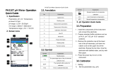
Instrument Description
LCD Display
Keypad Functions
Momentary press ----- <1.5 seconds
Long press ----- >1.5 seconds.
Turn on the meter
Press to turn on the meter: LCD full display → display
some parameters → display the last measurement mode.
Turn off the meter
In the measurement mode, press and hold for 2
seconds to turn off the meter.
Note: In the calibration mode or the parameter set-up mode, press for return to the measurement mode, then press
to turn off the meter.
TDS
(1) — Parameter mode icons
(2) — Measurement reading
(3) — Prompts of special display mode
(4) — Units of measurement
(5) — Temperature units (°C and °F)
(6) — Units of pH and conductivity calibration value
(7) — pH and conductivity calibration value
(8) — Temperature value,
(9) — Temperature compensation icons
ATC — automatic T compensation,
MTC — manual T compensation
(10) — Calibration guide icon
(11) — Stability icon of readings
(12) — Battery

7
7+Series Version 2.0
Keypad
Operations
Descriptions
Momentary press
• In the power-off mode, press this key to turn on the meter
• In the calibration mode or the parameter set-up mode, press this key to
return to the measurement mode
Long press
In the measurement mode, press and hold this key for 2 seconds to turn off the
meter.
Momentary press
• pH7+DHS: press this key to select measurement mode: pH → mV,
• Cond7+: press this key to select measurement mode: COND→TDS
• PC7+DHS pH/Conductivity meter: press this key to select
measurement mode: pH → mV → COND → TDS
Momentary press
In the measurement mode, press this key to enter in the calibration mode
Momentary press
• In the measurement mode, press this key to enter in the parameter
set-up main menu
• In the calibration mode, press this key to confirm calibration
• In the parameter set-up mode, press this key to select programs
Long press
In the mode of manual temperature compensation (MTC), when press and hold
these keys, the temperature value flashes, then press this keys to change the
temperature value, and press to confirm
Momentary press
In the setup menu and submenu, these keys increases and decreases the value
of the selected parameter (up and down direction)
Meter Connections
Models
Photos
Description
pH7+ DHS
•BNC socket— pH electrode or ORP electrode
•RCA socket —temperature probe
COND7 +
•BNC socket— conductivity electrode,
•RCA socket — temperature probe
PC7 + DHS
•BNC socket —pH electrode or ORP electrode,
•BNC socket— conductivity electrode,
•RCA socket— temperature probe

8
7+Series Version 2.0
Stability indication
When the measuring value is stable, smiley icon appears on LCD.
If the smiley icon does not appear or flash, please do not get the reading value, or make calibration until the measuring
value is stable.
In the parameter P1.6, there are 3 criteria for stability standard:
-Normal (default) -High (longer time) - Low (shorter time.)
User can select suitable stability criteria according to different testing requirement.
Parameter selection
Only for PC7+DHS, enter in the setup menu P6.6, one by one the parameters blinks on the top left of the LCD;
press and keys for choose Yes (parameter enabled) or No (parameter disable) .Then press key to
confirm. Press key to return in measurement mode.
Automatic Power Off
If the meter stops operation for 20 minutes, It will turn off automatically. In the setup menu P6.8 the user has the
possibility to disable this option.
DHS Technology
DHS technology, developed by Giorgio Bormac company, allows to save calibration data inside the memory of the pH
electrode.
It is possible to calibrate the XS DHS electrode in laboratory, in ideal conditions, using a XS DHS meter.
Calibration data, like date, slope, model and batch number, are memorized inside the electrode.
Moving this electrode on another XS meter DHS compatible, the electrode is ready for high quality measurement,
extremely safety and without a new calibration.
Simply useful: XS Meters DHS compatible recognize automatically If a XS sensor DHS is connected.
If not, the instrument will work as a standard pH meter.
And the same is for the electrode: Is possible to connect a XS sensor DHS on a standard XS meter (NO DHS compatible)
It will work as a standard pH electrode.
XS DHS sensors use just a BNC plug for the pH, and a RCA/Cinch plug for the temperature, exactly the same connectors
of the standard XS electrodes.
And It hasn’t the battery, so It is possible to stock the electrode as normal one.
After connecting the XS electrode DHS, meter will recognize It automatically, and display sequentially:
To calibrate the DHS sensor follow the calibration procedure at page 10 (pH meter calibration).
When the DHS electrode is disconnected, display shows:
DHS activation and disabling occur only in measurement mode.
sensor model
Batch number
pH
No
dhs
Calibration points
dhs
pH
pH
year
Slope
100
%
Month
day
Date of the last calibration

9
7+Series Version 2.0
pH Measurement
pH electrode information
On this meter is possible to use electrode with integrated temperature sensor else link two different probes for pH and
temperature.
The BNC socket of electrode connects pH socket, RCA socket connects temperature socket. When dip the electrode in
the solution, please stir the solution briefly and allow it to stay in the solution until a stable reading is reached.
pH calibration consideration - Standard buffer solution
The meter uses two series of standard buffer solution: USA series and NIST series, and also customer-defined solution.
Please see the table below for the two series of standard buffer solution. For customer-defined solution, please select it
in setup menu parameter P1.1.
Icons
pH standard buffer solution series
USA series
NIST series
Three-point calibration
1,68 pH and 4.00 pH
1,68 pH and 4.01 pH
7.00 pH
6.86 pH
10.01 pH
9.18 pH
Three-point calibration
The instrument can perform 1-3 point calibration. The first point of calibration must be 7.00 pH (or 6.86 pH) standard
solution, then select other standard solution to perform the second and the third point calibration; the meter is able to
recognize the buffer solutions in analysis. During the calibration process, the instrument displays the slope of acidity
range and alkalinity range respectively.
USA standard
NIST standard
Icons
Suited range
One-point calibration
7.00 pH
6.86 pH
Accuracy
≤ ±0.1pH
Two-point calibration
7.00 pH and
4.00 pH or 1,68 pH
6.86 pH and
4.01 pH or 1,68 pH
Range<7.00pH
7.00 pH and 10.01 pH
6.86 pH and 9.18 pH
Range>7.00pH
Three-point calibration
7.00 pH, 4.00 pH or 1,68
pH, 10.01 pH
6.86 pH, 4.01 pH or
1,68 pH, 9.18 pH
Large Range
Calibration Intervals
Calibration intervals depend on the sample, the electrode performance, and the required accuracy. For high accuracy
measurements (≤ ±0.02pH), the meter should be calibrated immediately before taking a measurement. For general
accuracy (≥±0.1pH), the meter can be calibrated and used for approximately one week before the next calibration.
The meter must be recalibrated in the following situations:
(a) New probe, or probe that is unused for a long period of time
(b) After measuring acids (pH<2) or alkaline solutions (pH>12)
(c) After measuring a solution that contains fluoride or a concentrated organic solution

10
7+Series Version 2.0
pH Meter Calibration
Press key to enter into the calibration mode, “CAL 1” blinks at the top right of LCD and “7.00 pH ”blinks at the
bottom right of LCD, indicating using pH 7.00 buffer solution to make the 1st point calibration.
Rinse pH electrode in pure water, allow it to dry, and submerge it in pH 7.00 buffer solution. Stir the solution gently
and leave it in the buffer solution until a stable reading is reached. The meter’s display will show scanning and locking
process of calibration buffer solution at the bottom right of LCD.
Er 2 displays if press key before the value is stable.
When the meter locks 7.00 pH, stable icon displays on LCD. Press key to calibrate the meter.
“End” icon appears after calibration is done. After the 1st point calibration, the meter’s display will show at the top
right a blinking CAL2, and show at the bottom right blinking 4.00pH and 10.01pH alternately, indicating using pH4.00
or pH10.01 buffer solution to make the 2nd point calibration.
Take out pH electrode,rinse it in pure water, allow it to dry, and submerge it in pH4.00 buffer solution.
Stir the solution briefly and allow it to stay in the buffer solution until a stable reading is reached. The meter’s
display will show scanning and locking process of calibration buffer solution at the bottom right of LCD. When the
meter locks 4.00 pH, stability icon displays on LCD. Press key to calibrate the meter.
Display shows “End” and slope.
The meter’s display will show at the top right a blinking CAL3, and show at the bottom right blinking 10.01pH,
indicating using pH10.01 buffer solution to make the 3rd point calibration.
Take out pH electrode,rinse it in pure water, allow it to dry, and submerge it in pH10.01 buffer solution. Stir the
solution briefly and allow it to stay in the buffer solution until a stable reading is reached. The meter’s will show
scanning and locking process of calibration buffer solution at the bottom right of LCD. When the meter locks 10.01 pH,
stable icon appears on LCD. Press key to calibrate the meter.
Display shows “End” icon and slope. Than the meter goes automatically to the measurement mode, displays stable
measuring value and calibration guide icons.
During the calibration process, press key to exit from the calibration mode. The meter can perform one-
point, two-point and three-point calibration. Calibration guide icons appear on LCD.

11
7+Series Version 2.0
Customer calibration
example of 1.60pH and 6.50pH calibration solution
Select CUS in the setup menu P1.1 (please refer to clause 7.3 for customer-defined solution). The meter enters into
Customer-defined calibration mode. Press key, the meter’s display show a blinking CAL1 icon at the top right of
LCD, indicating the meter enters into the 1st point customer-defined calibration.
Rinse pH electrode in pure water, allow it to dry, and submerge it in pH1.60 buffer solution. Stir the solution briefly and
allow it to stay in the buffer solution until a stable reading is reached. For automatic temperature compensation (ATC),
the temperature value does not blink. When press key, the main value blinks.
Press and keys to adjust the main value to 1.60, then press key to calibrate the meter. After calibration
is done, LCD at the top right shows blinking CAL2 icon, indicating the meter enters into the 2nd point customer-defined
calibration.
Note: For manual temperature compensation (MTC), when LCD displays the stable measuring value and icon,
press key, then the temperature value blinks, press and keys to adjust the
temperature value, and press key to confirm it. Then the main value blinks. Follow the above procedures to
adjust the main value and calibrate the meter.
Rinse pH electrode in pure water, allow it to dry, and submerge it in pH 6.50 buffer solution. Stir the solution briefly and
allow it to stay in the buffer solution until a stable reading is reached. For automatic temperature compensation (ATC),
the temperature value does not blink. When press key, the main value blinks.
Press and keys to adjust the main value to 6.50, then press key to calibrate the meter. After calibration
is done, the meter goes to the measurement mode. For customer-defined calibration, LCD does not show electrode
calibration guide icons.
Note: For manual temperature compensation (MTC), when LCD displays the stable measuring value and icon,
press key, then the temperature value blinks, press and key to adjust the temperature value, and
press key to confirm it. Then the main value blinks. Follow the above procedures to adjust the main value and
calibrate the meter.
The meter can perform 1-2 point customer-defined calibration. When the 1st point calibration is done,
press key, the meter exits from calibration mode. This is one-point customer-defined calibration.
As for the standard calibration the meter show on the LCD one or more icons indicating the suited range
User’s pH buffer
Icons show on the display
6.5 – 7.5
< 6.5
> 7.5

12
7+Series Version 2.0
Measurement
Rinse pH electrode in pure water, allow it to dry, and submerge it in tested solution. Stir the solution briefly and allow
it to stay in the tested solution until icon appears on LCD and a stable reading is reached which is pH value of
tested solution.
Self-diagnosis information
Display Icons
Contents
Checking
Wrong pH buffer solution or the
recognition of calibration solution out of
range
1.Check whether pH buffer solution is correct.
2.Check whether the meter connects the
electrode well.
3.Check whether the electrode is damaged.
Press key when measuring value is not
stable during calibration.
Press key when icon appears
During calibration, the measuring value is not
stable for ≥3min.
1.Check whether there are bubbles in glass bulb.
2.Replace with new pH electrode.
Electrode zero electric potential out of
range (<-60mV or >60mV)
1.Check whether there are bubbles in glass bulb.
2.Check whether pH buffer solution is correct.
3.Replace with new pH electrode.
Electrode slope out of range
(<85%or >110%)
pH measuring range out of range (<0.00 pH
or >14.00pH)
1.Check whether the electrode is suspended.
2.Check whether the meter connects the
electrode well.
3.Check whether the electrode is damaged
Factory default setting
For factory default setting, please refer to parameter P1.5. Per parameter P1.5, all calibration data is deleted
and the meter restores to the theory value (zero electric potential of pH is 7.00, the slope is 100%). Some
functions restore to the original value (refer to appendix -1). When calibration or measurement fails, please
restore the meter to factory default setting and then perform re-calibration or measurement. Please note
once set the factory default, all the data deleted will not be retrievable.
When the 1st point calibration is
done, press key to return
in measurement mode.
After the 3rd point calibration, the
meter enters into the
measurement mode
automatically.
Press to turn on
the meter
Press key to enter
into the calibration
mode
Submerge the electrode in pH
7.00 solution, press key
when icon appears
Sample
test
When the 2nd point calibration is
done, press key to return
in measurement mode.
Submerge the electrode in pH
4.01 solution, press key
when icon appears
Submerge the electrode in pH
10.01 solution, press key
when icon appears

13
7+Series Version 2.0
pH electrode maintenance
Daily maintenance
The soaking solution contained in the supplied protective bottle is used to maintain activation in the glass bulb and
junction. Loosen the capsule, remove the electrode and rinse in pure water before taking a measurement. Insert the
electrode and tighten the capsule after measurements to prevent the solution from leaking. If the soak solution is turbid
or moldy, replace the solution.
The electrode should not be soaked in pure water, protein solution or acid fluoride solution for long periods of time. In
addition, do not soak the electrode in organic silicon lipids.
For best accuracy, always keep the meter clean and dry, especially the meter’s electrode and electrode jack. Clean with
medical cotton and alcohol if necessary.
Calibration buffer solution
For calibration accuracy, the pH of the standard buffer solution must be reliable. The buffer solution should be refreshed
often, especially after heavy use.
Protect glass bulb
The sensitive glass bulb at the front of the combination electrode should not come in contact with hard surfaces.
Scratches or cracks on the electrode will cause inaccurate readings. Before and after each measurement, the electrode
should be washed with pure water and dried. Do not clean the glass bulb with a tissue for it will affect the stability of
the electrode potential and increase the response time. The electrode should be thoroughly cleaned if a sample sticks
to the electrode. Use a solvent if the solution does not appear clean after washing.
Regenerate glass bulb
Electrodes that have been used over a long period of time, will become ageing. Submerge the electrode in 0.1mol/L
hydrochloric acid for 30 seconds, then wash the electrode in pure water, then submerge it in soaking solution for 24
hours.
Clean contaminated glass bulb and junction (please refer to Chart-6)
Contamination
Abluent
Inorganic metal oxide
Dilute acid less than 1mol/L
Organic lipid
Dilute detergent (weak alkaline)
Resin macromolecule
Dilute alcohol, acetone, ether
Proteinic haematocyte sediment
Acidic enzymatic solution (saccharated yeast tablets)
Paint
Dilute bleacher, peroxide
Note: if the electrode housing is polycarbonate. When use abluent, take cautions on carbon tetrachloride,
trichlorethylene, tetrahydrofuran, acetone, etc which will dissolve the housing and invalidate the electrode.
mV measurement
Press key, and switch the meter to mV measurement mode.
Connect ORP electrode (need purchase it separately) and dip it in sample solution, stir the solution gently and leave It
solution until icon appears, and get the reading which is ORP value.
ORP means Oxidation Reduction Potential. The unit is mV.

14
7+Series Version 2.0
ORP
ORP measurement does not require calibration. When the user is not sure about ORP electrode quality or measuring
value, use ORP standard solution to test mV value and see whether ORP electrode or meter works properly.
Clean and activate ORP electrode
After the electrode has been used over long period of time, the platinum surface will get polluted which causes
inaccurate measurement and slow response. Please refer to the following methods to clean and activate ORP
electrode:
• For inorganic pollutant, submerge the electrode in 0.1mol/L dilute hydrochloric acid for 30 minutes, then
wash it in pure water, then submerge it in the soaking solution for 6 hours.
• For organic or lipid pollutant, clean the platinum surface with detergent, then wash it in pure water, then
submerge it in the soaking solution for 6 hours.
• For heavily polluted platinum surface on which there is oxidation film, polish the platinum surface with
toothpaste, then wash it in pure water, then submerge it in the soaking solution for 6 hours.
Conductivity
Conductivity cell
Two-ring cells with built-in temperature sensor can be used on this instrument. The conductivity cell uses a BNC
connector while the temperature probe uses an RCA connector. When submerge the conductivity electrode in
solution, stir the solution briefly to eliminate the air bubbles and improve response and stability.
Conductivity cell constant
The meter matches conductivity electrodes of three constants: K=0.1, K=1.0 and K=10.0. Please refer to chart below
for measuring range. Set constant per parameter P2.1.
Range
<20 μS/cm
0.5 μS/cm~100 mS/cm
>100mS/cm
Conductivity electrode
constant
K=0.1 cm-1
K=1.0 cm-1
K=10 cm-1
Standard solution
84μS/cm
84 μS/cm
1413 μS/cm
12.88 mS/cm
111.9 mS/cm
Conductivity calibration solutions
The meter uses conductivity standard solution of USA series. The meter can recognize the standard solution
automatically, can perform one-point or multi-point calibration (the maximum is four-point calibration). The calibration
guide icons at the bottom left of LCD correspond to the four standard values.
Calibration guide icons
Calibration solution series
Range
84 μS/cm
0-200 μS/cm
1413 μS/cm
200-2,000 μS/cm
12.88 mS/cm
2-20 mS/cm
111.9 mS/cm
20-200 mS/cm

15
7+Series Version 2.0
Calibration intervals
• The meter is calibrated before leaving the factory and can generally be used right out of the box.
• Normally perform calibration per month.
• For high accuracy measurements or large temperature deviation from the reference temperature (25°C),
perform calibration per week.
• Use conductivity standard solution to check whether there is error. Perform calibration for large error.
• For new electrode or factory default setting, perform 3-point or 4-point calibration. Choose closer
standard solution to the sample solution to perform 1- point or 2-point calibration. For example: 1413
μS/cm standard solution is suited for range 0-2,000 μS/cm.
1-point and multi-point calibration
For 1-point calibration after 3-point or 4-point calibration, the previous calibration value in the same range will
be replaced, meanwhile, the meter will show the calibration guide icon of this point, other two calibration guide
icons will be deleted, but the chip will reserve the last calibration data. When choose multi-point calibration,
perform calibration from low to high concentration to avoid standard solution of low concentration being
contaminated.
Reference temperature
Reference temperature of factory default is 25°C. Other reference temperature can also be set for range 15°C –
30°C. Select per parameter P2.5.
Temperature coefficient
The temperature compensation coefficient of the meter setting is 1.91%. However, the conductivity temperature
coefficient is different for solutions of a different variety and concentration. Set per parameter P2.6..
Note: When the coefficient for the temperature compensation is set to 0.00 (no compensation), the measurment
value will be based on the current temperature.
Solution
Temperature compensation coefficient
NaCl solution
2.12%/°C
5% NaOH solution
1.72%/°C
Dilute ammonia solution
1.88%/°C
10% hydrochloric acid solution
1.32%/°C
5% sulfuric acid solution
0.96%/°C
Avoid contamination of standard solution
Conductivity standard solution has no buffer. Please avoid being contaminated during usage. Submerge the electrode
in standard solution before wash the electrode and allow it dry. Please renew conductivity standard solution
frequently especially for standard solution of low concentration 84μS/cm. The contaminated standard solution can
affect accuracy.

16
7+Series Version 2.0
Conductivity Calibration
example of calibration at 1413μS/cm
Rinse conductivity electrodes in pure water, allow it to dry, wash with a little of standard solution and submerge it in
standard solution. Stir the solution briefly and allow it to stay in the solution until a stable reading is reached.
Press key to enter into the calibration mode. The meter’s display will show blinking “std” at the top right, and
scanning and locking process of calibration solution at the bottom right.
Er 2 appears if press key before the value is stable.
When the meter locks 1413 μS, stability icon displays on LCD. Press key to calibrate the meter. End icon appears
after calibration is done. The meter returns to the measurement mode
and LCD shows icon at the bottom left.
If return from calibration mode without calibration, press key to return to the measurement mode without
calibration.
For multi-point calibration repeat the procedure.
Customer calibration
example of calibration at 147μS/cm
Select CUS in the setup menu P2.2; the meter enters into customer-defined calibration mode. When press LCD
shows blinking CUS at the top right, indicating that the meter enters into customer-defined calibration.
Rinse the electrode in pure water, allow it to dry, and submerge it in 147 μS/cm standard solution. Stir the solution
briefly and allow it to stay in the solution until a stable reading is reached and stability icon appears on LCD.
When press key, the measuring value blinks. “CUS” icon appears at the right top of the screen. Press
and key to adjust the measuring value to 147 μS/cm, and press key to calibrate the meter. After the
calibration is done, the screen shows “End” icon and returns to the measurement mode.
Note: When there is no temperature sensor and manual temperature compensation (MTC) is adopted, the
Submerge the cell in a conductivity standard
solution:
•84 μS L
•1413 μS M
•12.88mS H
•111.9mS H
Press key when icon appears, to
confirm the calibration, the meter enters into
measurement mode automatically.
Sampe
Test
Press to turn
on the meter
Press key to
enter into the
calibration mode
Multipoint calibration
Single point
calibration

17
7+Series Version 2.0
temperature value blinks when press key, press and key to adjust the temperature value, and
when press key, conductivity value blinks.
Only 1-point calibration for customer-defined calibration. The value set in “customer-defined” is at a fixed
temperature. There is no regulations of temperature coefficient and reference temperature. The meter has to perform
calibration and measurement at the same temperature to avoid large error. The meter cannot recognize customer-
defined calibration solution.
As for the standard calibration also in customer calibration the meter show on the LCD one icon indicating the suited
range.
Display icon
Suited range
< 1300 μS/cm
1300 - 1500 μS/cm
> 1500 µS/cm
Measure
Rinse conductivity electrode in pure water, allow it to dry, and submerge it in the sample solution. Stir the solution
briefly and allow it to stay in the sample solution until a stable reading is reached and stability
icon appears on LCD, then get the reading value which is the conductivity value of the solution.
During the process of calibration and measurement, the meter has self-diagnosis functions
Display Icons
Contents
Checking
Wrong conductivity calibration solution or
the meter recognition of calibration
solution out of range
1.Check whether conductivity calibration
solution is correct.
2.Check whether the meter connects the
electrode well.
3.Check whether the electrode is damaged.
Press key when measuring value is
not stable during calibration.
Press key when icon appears
During calibration, the measuring value is
not stable for ≥3min.
1.Shake the electrode to eliminate bubbles in
electrode head.
2.Replace with new pH electrode.
Factory default setting
For factory default setting, please refer to parameter P2.8. All calibration data is deleted and the meter restores to the
theory value. Some functions restore to the original value (refer to appendix -1). When calibration or measurement fails,
please restore the meter to factory default setting and then perform re-calibration or measurement. Please note once
set the factory default, all the data deleted will not be retrievable.

18
7+Series Version 2.0
Conductivity electrode maintenance
Always keep the conductivity electrode clean. Before taking a measurement, rinse the electrode in pure water and
then rinse it in the sample solution. When submerge the electrode in solution, stir the solution briefly to eliminate air
bubbles and allow it to stay until a stable reading is reached. For conductivity electrode which keeps dry, soak the
electrode in pure water for 5-10 minutes. Rinse the electrode in pure water after measurement.
If the electrode coated with platinum black is invalid, immerse it in 10% nitric acid solution or 10% hydrochloric acid
solution for 2 minutes, then rinse the electrode in pure water. If the electrode still does not work, re-coat platinum
black, or replace with a new conductivity electrode.
Relations between TDS and conductivity
TDS and conductivity is linear related, the conversion factor is 0.40-1.00. Adjust per parameter P3.1. The factory
default setting is 0.71. The meter can only be calibrated in Conductivity mode and not TDS mode. After
calibration of conductivity, the meter can switch from conductivity to TDS.
Adjust TDS conversion factor per parameter P3.1 according to the data collected during testing
Common used TDS conversion factors
Conductivity of solution
TDS conversion factor
0-100 μS/cm
0.60
100-1,000 μS/cm
0.71
1-10 mS/cm
0.81
10-100 mS/cm
0.94
Setup Menu
Main menu
In the measurement mode, press key to enter in P1.0, then press and to slide the main menu:
P1.0→P2.0→P3.0→P6.0.
P1.0: pH parameter setting menu,
P2.0: Conductivity parameter setting menu,
P3.0: TDS parameter setting
P6.0: Basic parameter setting menu.
Submenu
In P1.0 mode, press key to enter in submenu P1.1 of pH parameter setting, then press and keys to
switch among submenu: P1.1→P1.4→P1.5→P1.6→P1.7.
In P2.0 mode, press key to enter in submenu P2.1 of conductivity parameter setting, then press and
keys to switch among submenu: P2.1→P2.2→P2.5→P2.6→P2.8→P2.9.
In P3.0 mode, press key to enter in submenu P3.1 to adjust TDS factor.
In P6.0 mode, press key to enter in submenu P6.1 of basic parameter setting, then press and keys to
switch among submenu: P6.1→P6.6→P6.8.

19
7+Series Version 2.0
P1.1 Select pH standard solution
P1.4 Select resolution
P1.5 Restore to factory setting
P1.6 Set stability criteria
P1.7 Temperature calibration
P2.1 Select electrode constant
P2.2 Select conductivity standard solution
P2.5 Select reference temp.
P2.6 Adjust temperature
compensation coefficient
P2.8 Restore to factory setup
P2.9 Temperature calibration
P6.1 Select temperature unit
P6.6 Parameters selection
P6.8 Automatic power-off setup
Submenu of pH parameter setting
P3.1 Adjust TDS factor
Main menu of parameter setting
Submenu of conductivity parameter setting
Submenu of TDS parameter setting
Submenu of basic parameter setting

20
7+Series Version 2.0
Submenu of pH parameter setting (pH7+DHS, PC+DHS)
Select pH standard solution (USA-NIST-CUS)
In P1.0 mode, press to enter in P1.1, refer to the left Diagram.
When press key, USA blinks, press directional keys to select blinking
NIST→CUS. When parameter blinks, press to confirm ( USA series: 1,68 pH,
4.00 pH, 7.00 pH, 10.01 pH, NIST series: 1,68 pH, 4.01 pH, 6.86 pH, 9.18 pH, CUS
– customer-defined).
After confirm parameter, press key to return to the measurement mode.
Select resolution (0.01 – 0.1)
Press key, 0.01 blinks, press directional keys, 0.1 blinks, when
parameter blinks, press key to confirm.
After confirm parameter, press to return to the measurement mode.
Restore factory setting (No – Yes)
1. Press key, No blinks, press directional keys, Yes blinks, press
key to confirm, the meter returns to the measurement mode.
No – Do not restore Yes – Restore to factory setting.
2. Press key to return to the measurement mode.
Set reading stability criteria (Normal – High – Low)
Press key, nor blinks. Press directional keys, Hi and then Lo blinks. When
parameter blinks, press to confirm.
Nor – Normal, Hi – High, Lo – Low.
Press key to return to the measurement mode.
Temperature Calibration ( Calibration range ±5℃)
1. Press key, the temperature value blinks, press directional keys to adjust
the temperature value, press key to confirm.
2. When parameter is confirmed, press key to return to the measurement
mode.
Note: When make calibration, insert the temperature probe in the standard
temperature source (eg. thermostatic bath) and calibrate until the display value
is stable. The calibration range is ±5℃. When set up “Yes” in P1.5, the
temperature value restores to factory setting.
/