Page is loading ...

Installation and operation guide
flowIQ® Gateway
Kamstrup A/S · Industrivej 28, Stilling · DK-8660 Skanderborg · T: 89 93 10 00 · [email protected] · kamstrup.com

2 Kamstrup A/S • 55122714_A2_GB_04_2021
flowIQ® Gateway
Disclaimer
All information provided in this document is copyright of Kamstrup. Licence is granted to the user
to freely use and distribute the information in complete and unaltered form, provided that the
purpose is to use or evaluate Kamstrup products. Distribution rights do not include public posting
or mirroring on Internet websites. Only a link to the Kamstrup website can be provided on such
public websites.
Kamstrup shall in no event be liable to any party for direct, indirect, special, general, incidental, or
consequential damages arising from the use of this information or any derivative works thereof.
The information is provided on an as-is basis, and thus comes with absolutely no warranty, either
express or implied. No right or licence is granted under any intellectual property right, hereunder
copyright, patent or trademark, of Kamstrup to any other party. This disclaimer includes, but is
not limited to, implied warranties of merchantability, fitness for any particular purpose, and non-
infringement.
Information in this document is subject to change without notice and should not be construed as
a commitment by Kamstrup. While the information contained herein is believed to be accurate,
Kamstrup assumes no responsibility for any errors and/or omissions that may appear in this
document.
Copyright Information
Copyright ® Kamstrup A/S
Industrivej 28
Stilling
DK-8660 Skanderborg, Denmark
All Rights Reserved
The graphics and content in this document are the copyrighted work of Kamstrup and contain
proprietary trademarks and trade names of Kamstrup.
Third parties
This document may contain links to other parties. Kamstrup makes no warranty or representation
regarding any linked information appearing therein. Such links do not constitute an endorsement
by Kamstrup of any such information and are provided only as a convenience. Kamstrup is not
responsible for the content or links displayed by third parties.

3Kamstrup A/S • 55122714_A2_GB_04_2021
flowIQ® Gateway
Contents
1 Symbols used in this document 5
1.1 Warnings in the document 5
2 Abbreviations 7
3 Technical data 7
3.1 Product introduction 7
3.2 Electrical data 8
3.3 Mechanical data 8
3.4 Material 8
3.5 Communication 9
3.6 Input 9
3.7 Connections and inputs 9
3.7.1 Primary connection terminals 9
3.7.1.1 Supported flowIQ® meters 10
3.7.1.2 Supported data from flowIQ® 2200/3200 meters 10
3.7.1.3 Supported info codes from flowIQ® 2200/3200 meters 10
3.7.2 Module slot 1 and 2 10
3.7.2.1 Supported communication modules 11
4 Before you begin 12
4.1 What is in the box? 12
4.2 Accessories (ordered separately) 12
4.3 Deployment summary 12
5 Before field deployment 13
5.1 Import flowIQ® Gateway in meter data management systems 13
5.1.1 Automatic import in READy Manager 13
5.1.2 Manual import in READy Manager 13
5.1.3 Import in a third-party MDM system 13
6 Field deployment - installation 14
6.1 Installation 14
6.1.1 Wall installation 14
6.2 Connecting flowIQ® Gateway with flowIQ® 2200/3200 meter 15
6.3 Plugging in communication module(s) 16
6.3.1 Antenna mounting 16
6.4 Connecting additional accessories 17
6.4.1 Connecting Pt500 temperature sensors 17
6.4.2 Connecting pulse meters 18
6.4.3 Connecting Analog input 4…20 mA devices 18
6.5 Connecting the power supply 19
6.5.1 Battery supply 19
6.5.2 Mains supply 19
7 Field deployment – Configuration 21
7.1 Configuration of flowIQ® Gateway 21
7.1.1 Display loops 23
7.1.1.1 "USER loop" 23
7.1.1.2 "SETUP loop" 25
7.1.1.3 Overview of the "SETUP loop" index 26
7.1.1.4 "TECH loop" 26
7.1.2 Activation and deactivation of radio 27
7.2 Configuration of communication module(s) 27
7.2.1 Pulse configuration 28
7.2.1.1 Pulse In-A and In-B 28
7.2.1.2 Pulse cold water leakage 28
7.2.1.3 Pulse output 28

4 Kamstrup A/S • 55122714_A2_GB_04_2021
flowIQ® Gateway
8 Operation 29
8.1 Normal operation 29
8.2 Alarms and info codes 29
8.3 flowIQ® Gateway and meter exchanges in READy Manager 31
8.3.1 flowIQ® Gateway exchange 31
8.3.2 flowIQ® 2200/3200 meter exchange connected to flowIQ® Gateway 31
8.4 Kamstrup support 31
9 Disposal 32
9.1 Disposal by Kamstrup A/S 32
9.2 The customer sends for disposal 32
9.3 Disposal by the customer 32
10 Communication module combinations and examples 34

5Kamstrup A/S • 55122714_A2_GB_04_2021
flowIQ® Gateway
1 Symbols used in this document
Indicates a hazardous situation which, if not avoided, could result in death or serious
injury.
Indicates a hazardous situation which, if not avoided, could result in moderate injury,
damage the product, or lead to loss of data.
Indicates a hazardous situation which, if not avoided, may seriously impact operations.
1.1 Warnings in the document
The contents of this guide and the guide included with the device must be followed at all times
when installing, configuring or handling the device in general. If this guide is not followed,
Kamstrup cannot be held accountable for any malfunctions or misuse of the product.
Fire, explosion and severe burn hazard.
Please follow these guidelines in order to avoid injury to yourself and others:
• If not disposed of properly, the battery may cause fire or chemical burn
• Do NOT recharge, disassemble, crush, expose to water, heat above (100 °C) or
incinerate the battery
• Keep away from children
By connecting to 230 V supply, there is a risk of electric shock.
Use only approved accessories with this device. Unapproved modifications or operation
beyond or in conflict with these instructions for use may void authorization by the
authorities to operate the device.
Do not install outside of lightning protection zone 0C. 3 m height and depth around the
building.
By connecting to 24 V or 230 V supply, there is a risk of electric shock.
Ensure proper disposal of the product.
flowIQ® Gateway is designed to operate at temperatures of 5 °C…55 °C. Using the device
outside the intended operating temperature range may cause deterioration of battery
life or in worst case operating failure.
If used with a radio module, the device must be installed to provide a separation
distance of minimum 20 cm from all persons.
Must NOT be co-located in conjunction with any other antenna or transmitter.
Billing data can be corrupted if you do not follow the instructions found in section 8.3
"flowIQ® Gateway and meter exchanges in MDM" when performing exchanges of meters
or gateways.

6 Kamstrup A/S • 55122714_A2_GB_04_2021
flowIQ® Gateway
If used with a radio module, mount flowIQ® Gateway at least 15 cm from pipes and
conduits and several centimetres below the ceiling.
If used with a radio module, mount flowIQ® Gateway at least 1.5 m away from any large
metal objects (e.g. refrigerators, HVAC ducts, furnaces and hot-water heaters).
If used with a radio module, do not mount flowIQ® Gateway directly under AC power
wires, circuit breaker panels or telecommunications wires.
Before replacing or mounting modules, the supply to the meter must be switched off.
The same applies for mounting of an antenna.
flowIQ® Gateway is an accessory gateway that syncs, shows and forwards meter data.
The connected flowIQ® 2200/3200 meter is the solution's legally approved entity (MID)
for billing data.
Temperature and Advanced Leak Detection data is not forwarded from flowIQ® Gateway.
If you wish to receive this data, import the flowIQ® meter in READy Manager.
Kamstrup offers support for the flowIQ® Gateway modules listed below only.
Modules are factory-mounted if ordered with flowIQ® Gateway.
Only one installed radio module is supported at the time.
Kamstrup recommends only importing flowIQ® Gateway or connected flowIQ® 2200/3200
meter in READy Manager. Not both.
When using flowIQ® Gateway as an installation point in READy Manager, only the
flow® Gateway serial number will be availbale in READy Manager.
If used with a radio module with internal antenna, it is recommended that flowIQ® Gateway
is mounted as high as possible near an exterior wall at/or above ground level.
If used with a radio module with external antenna, it is recommended that the antenna
is mounted as high as possible near an exterior wall at/or above ground level.
If the modules are ordered with flowIQ® Gateway, they are factory-mounted.
All radio-based modules must have either an internal or external antenna connected.
Please note that it is only possible to configure the gateway 50 times via "SETUP loop".
After 50 times, the gateway is locked against further configuration, and a total reset is
required.
Some items in "SETUP loop" are displayed as “OFF”. This means that the function is not
available in the gateway.
If the gateway's radio communication is switched off via "SETUP loop", the gateway
subsequently switches on the radio communication again when the connected
flowIQ® 2200/3200 meter registers water flow.
The symbols for radio on/off indicate whether the gateway allows radio communication,
not whether a radio module has activated its radio communication. Please be aware of
this when troubleshooting the gateway's wireless communication.
Remember to enable transport mode when exchanging or decommissioning a battery-
driven flowIQ® Gateway. If this is not done, the gateway will keep sending data to the
MDM system.

7Kamstrup A/S • 55122714_A2_GB_04_2021
flowIQ® Gateway
2 Abbreviations
MDM: meter data management
EKS: Encryption Key Service
3 Technical data
3.1 Product introduction
The contents of this guide and the guide included with the device must be followed at all times
when installing, configuring or handling the device in general. If this guide is not followed,
Kamstrup cannot be held accountable for any malfunctions or misuse of the product.
flowIQ® Gateway is an accessory gateway that syncs, shows and forwards meter data.
The connected flowIQ® 2200/3200 meter is the solution's legally approved entity (MID)
for billing data.
flowIQ® Gateway is a universal communication module gateway that connects to flowIQ® 2200/3200
meters from Kamstrup and forwards data via the chosen module communication protocol.
flowIQ® Gateway works with popular industrial protocols such as Modbus, BACnet, LonWorks and
integrates to Kamstrup's own meter data management system READy Manager with Wireless
M-Bus, P2P 2G/4G or linkIQ®.

8 Kamstrup A/S • 55122714_A2_GB_04_2021
flowIQ® Gateway
3.2 Electrical data
Fire, explosion and severe burn hazard.
Please follow these guidelines in order to avoid injury to yourself and others:
• If not disposed of properly, the battery may cause fire or chemical burn
• Do NOT recharge, disassemble, crush, expose to water, heat above (100 °C) or
incinerate the battery
• Keep away from children
By connecting to 230 V supply, there is a risk of electric shock.
Battery
3.65 VDC, D-cell lithium 3.65 VDC, 2xA-cell lithium
Battery lifetime 16 years @ tBAT < 30 °C 9 years @ tBAT < 30 °C
Note: Power supply choices depend on the inserted communication module and lifetime depends
on the chosen communication modules and datagrams.
Mains supply 230 VAC +15/-30 %, 50/60 Hz
24 VAC ±50 %, 50/60 Hz
24 VDC +75/-25 % (24 VDC for High Power SMPS only)
Power consumption < 1 w
Insulation voltage 3.75 kV
3.3 Mechanical data
flowIQ® Gateway is designed to operate at temperatures of 5 °C…55 °C. Using the device
outside the intended operating temperature range may cause deterioration of battery
life or in worst case operating failure.
Protection class IP65-rated
Dimensions 166 mm x 102 mm x 47 mm
Wall mount 74 mm x 58 mm
Weight Approx. 450 g
Operating temperature 5 °C…55 °C non-condensing closed location (indoor installation)
Storage temperature -25 °C…60 °C
Operating humidity 0 % - 100 % non-condensing
3.4 Material
Top and base Thermoplastic, PC 10 % GF with TPE (thermoplastic elastomer)
Verification cover ABS

9Kamstrup A/S • 55122714_A2_GB_04_2021
flowIQ® Gateway
3.5 Communication
If used with a radio module, the device must be installed to provide a separation
distance of minimum 20 cm from all persons.
Must NOT be co-located in conjunction with any other antenna or transmitter.
Communication module 2 plug-in slots
Antenna External/internal depending on communication module
Optical interface Configuration interface
3.6 Input
flowIQ® 2200/3200 meter Proprietary Kamstrup communication
Cable (ordered separately) 1.5 m 5000491
7.5 m (can be shortened) 5000493
Temperature sensors 3 x Pt500
3.7 Connections and inputs
3.7.1 Primary connection terminals
The primary connection terminals are reserved for connection of a flowIQ® 2200/3200 meter and
3 Pt500 temperature sensors.
Description Schematic Overview
The flowIQ® 2200/3200
meter cable is connected
in the following way:
Black à minus (-) input 11
Red à plus (+) input 9
Green à V1 input 10
The 3 Pt500 temperature
sensors are connected to
terminals t1…3
t2
t3
V1
V2
t1
+
-
-
+
-
+

10 Kamstrup A/S • 55122714_A2_GB_04_2021
flowIQ® Gateway
3.7.1.1 Supported flowIQ® meters
flowIQ® meters Proprietary Kamstrup communication
flowIQ® 2200 with wM-Bus/linkIQ® module 61/62
flowIQ® 3200 with wM-Bus/linkIQ® module 63/64
3.7.1.2 Supported data from flowIQ® 2200/3200 meters
Temperature and Advanced Leak Detection data is not forwarded from flowIQ® Gateway.
If you wish to receive this data, import the flowIQ® meter in READy Manager
The following data is synced between flowIQ® Gateway and flowIQ® 2200/3200 meters:
• Volume 1
• Flow (V1)
• Info codes (see the following section)
Please refer to the specific communication module's data sheet on products.kamstrup.com for
further information about data content.
3.7.1.3 Supported info codes from flowIQ® 2200/3200 meters
The connected flowIQ® 2200/3200 meters can forward the following alarms/info codes to
flowIQ® Gateway. The gateway maps the info codes to its own interpretation of the alarms/info codes:
flowIQ® Gateway flowIQ® 2200/3200
The connected meter is Dry V1 Air Dry
The connected meter has Reverse flow V1 Reverse Reverse
The connected meter has registered a Leak Leak out Leak
The connected meter has registered a Burst Burst out Burst
The connected meter has registered Flow above Q4V1 is above QsFlow above Q4
See section 8.2 "Alarms and info codes" for a complete overview of alarms and info codes.
3.7.2 Module slot 1 and 2
Module slots 1 and 2 are for plugging in modules offering different communication types and
protocols.
12

11Kamstrup A/S • 55122714_A2_GB_04_2021
flowIQ® Gateway
3.7.2.1 Supported communication modules
Kamstrup offers support for the flowIQ® Gateway modules listed below only.
Modules are factory-mounted if ordered with flowIQ® Gateway.
Only one installed radio module is supported at the time.
The following communication modules are supported by flowIQ® Gateway.
For examples of combinations and usage, see section 10 "Communication module combinations
and examples".
Article number Module Recommended
datagram
HC-003-10 Data Pulse, inputs (In-A, In-B)
HC-003-11 Data Pulse, outputs (Out-C, Out-D)
HC-003-20 Wired M-Bus, inputs (In-A, In-B)
HC-003-21 Wired M-Bus, outputs (Out-C, Out-D)
HC-003-32 linkIQ/wM-Bus, inputs (In-A, In-B), EU &
HC-003-33 linkIQ/wM-Bus, outputs (Out-C, Out-D), EU &
HC-003-41 Analog inputs 2 x 4…20 mA / 0…10 V 41-00-100 "
HC-003-60 LON TP/FT-10, inputs (In-A, In-B) 60-00-100 $
HC-003-66 BACnet MS/TP, inputs (In-A, In-B) 66-00-100 "
HC-003-67 Modbus RTU, inputs (In-A, In-B) "
HC-003-80 2G/4G Network, inputs (In-A, In-B) 80-10-101 &$
HC-003-82 Modbus/KMP TCP/IP, inputs (In-A, In-B) $
HC-003-83 READy Ethernet, inputs (In-A, In-B) 83-10-100 $
"The module requires that the meter is mains-supplied
$The module requires that the meter is mains-supplied with a High Power supply
&The module requires an antenna

12 Kamstrup A/S • 55122714_A2_GB_04_2021
flowIQ® Gateway
4 Before you begin
4.1 What is in the box?
• flowIQ® Gateway
• Wall bracket including screws and rawlplugs
• Ordered module(s) – mounted in gateway
4.2 Accessories (ordered separately)
See a complete list of accessories in the product data sheet.
The most commonly used are listed here:
• flowIQ® 2200/3200 meter connection cable
1.5 m (5000491)
7.5 m, can be shortened (5000493)
• Temperature sensors (Pt500)
All Pt500 2-wired sensors can be used
If a set of two or more sensors are bought from Kamstrup, the sensor set can be split to use one
sensor per flowIQ® Gateway
4.3 Deployment summary
1 Before field deployment (section 5):
Import flowIQ® Gateway in the meter data management system (encryption keys)
2 Field deployment - Installation (section 6):
Install flowIQ® Gateway
Connect flowIQ® 2200/3200 meter with flowIQ® Gateway
Plug in or check the communication module(s)
Connect additional accessories
Connect power supply
3 Field deployment - Configuration (section 7):
Configure flowIQ® Gateway
Configure the communication module(s) (if applicable)
0-2 pcs.

13Kamstrup A/S • 55122714_A2_GB_04_2021
flowIQ® Gateway
5 Before field deployment
If using a radio communication module in flowIQ® Gateway, it is required that you import the
encryption key file from EKS at My Kamstrup in your MDM system. Please follow the steps below.
5.1 Import flowIQ® Gateway in meter data management systems
5.1.1 Automatic import in READy Manager
Billing data can be corrupted if you do not follow the instructions found in section 8.3
"flowIQ® Gateway and meter exchanges in MDM" when performing exchanges of meters
or gateways.
Kamstrup recommends only importing flowIQ® Gateways or connected flowIQ® 2200/3200
meters in READy Manager. Not both.
When using flowIQ® Gateway as an installation point in READy Manager, only the
flow® Gateway serial number will be availbale in READy Manager.
If using Kamstrup's MDM system READy Manager, flowIQ® Gateway is automatically imported into
READy Manager if you are logged in with your My Kamstrup account and the "Import new devices"
checkbox is ticked.
More information can be found in the READy Manager user guide under "Automatically importing
information for new devices".
5.1.2 Manual import in READy Manager
If not logged in, you can import flowIQ® Gateway directly from EKS found in My Kamstrup.
Click the "Import devices" button on the start page of READy Manager and import the downloaded
encryption key file from EKS.
More information can be found in the READy Manager user guide under "Manually importing
information for new devices".
5.1.3 Import in a third-party MDM system
If using another MDM system and radio communication, the encryption key file must be manually
downloaded from EKS at My Kamstrup and imported in the MDM system.
If using a module with wired communication, data is not encrypted.

14 Kamstrup A/S • 55122714_A2_GB_04_2021
flowIQ® Gateway
6 Field deployment - installation
Use only approved accessories with this device. Unapproved modifications or operation
beyond or in conflict with these instructions for use may void authorization by the
authorities to operate the device.
Do not install outside of lightning protection zone 0C. 3 m height and depth around the
building.
6.1 Installation
flowIQ® Gateway is intended to be wall-mounted with the accompanying wall bracket in
residential, commercial and industrial environments. The device is intended to be installed either
at ground level or above ground on a wall. flowIQ® Gateway is IP65-rated and is resistant to
harmful dust and water sprays.
6.1.1 Wall installation
If used with a radio module, mount flowIQ® Gateway at least 15 cm from pipes and
conduits and several centimetres below the ceiling.
If used with a radio module, mount flowIQ® Gateway at least 1.5 m away from any large
metal objects (e.g. refrigerators, HVAC ducts, furnaces and hot-water heaters).
If used with a radio module, do not mount flowIQ® Gateway directly under AC power
wires, circuit breaker panels or telecommunications wires.
If used with a radio module with internal antenna, it is recommended that flowIQ® Gateway
is mounted as high as possible near an exterior wall at/or above ground level.
If used with a radio module with external antenna, it is recommended that the antenna
is mounted as high as possible near an exterior wall at/or above ground level.
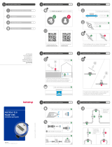
flowIQ® Gateway can be mounted on an even wall. Use the wall bracket
as a template to mark and drill two 6 mm holes in the wall and mount
the wall bracket with the enclosed screws and rawlplugs. Mount
flowIQ® Gateway on the wall bracket by sliding the device onto the bracket.
51

15Kamstrup A/S • 55122714_A2_GB_04_2021
flowIQ® Gateway
Mount the wall bracket and slide flowIQ® Gateway onto the bracket:
6.2 Connecting flowIQ® Gateway with flowIQ® 2200/3200 meter
Follow the connection diagram below:
Description Schematic Overview
The flowIQ® 2200/3200
meter cable is connected
in the following way:
Black à minus (-) input 11
Red à plus (+) input 9
Green à V1 input 10
The 3 Pt500 temperature
sensors are connected to
terminals t1…3
t2
t3
V1
V2
t1
+
-
-
+
-
+
Connect the plug to the flowIQ® 2200/3200 meter:
Mount the connection cable on the
flowIQ® 2200/3200 meter.
Insert the locking tabs in the
assembly to secure the connection.

16 Kamstrup A/S • 55122714_A2_GB_04_2021
flowIQ® Gateway
6.3 Plugging in communication module(s)
Before replacing or mounting modules, the supply to the meter must be switched off.
The same applies for mounting of an antenna.
If the modules are ordered with flowIQ® Gateway, they are factory-mounted.
The communication modules are factory-mounted if
ordered with flowIQ® Gateway.
If ordered separately, mount the modules as shown.
The communication modules are programmed with a data
package at the factory and will send data according to the
chosen package.
6.3.1 Antenna mounting
All radio-based modules must have either an internal or external antenna connected.
When mounting an external antenna, please ensure that the antenna cable is arranged as shown
to prevent damage of the cable when the gateway is assembled.
Before opening the gateway to mount a module or an antenna, the power supply must be
disconnected.
Wireless M-Bus module with internal antenna. Wireless M-Bus module with external antenna.

17Kamstrup A/S • 55122714_A2_GB_04_2021
flowIQ® Gateway
6.4 Connecting additional accessories
Additional devices can be connected to flowIQ® Gateway. These devices are dependent on the
choice of communication module. The devices include:
• Up to 3 x Pt500 temperature sensors
• Up to 4 x pulse meters
• Up to 2 x analog input 4...20 mA devices, e.g. pressure sensors
6.4.1 Connecting Pt500 temperature sensors
Up to 3 x Pt500 temperature sensors can be connected to flowIQ® Gateway.
Description Schematic Overview
The flowIQ® Gateway Pt500
temperature sensors are
connected in the following
way:
• Connect the two wires
to either the t1, t2, or t3
terminals as shown
t2
t3
V1
V2
t1
+
-
-
+
-
+
5
6
8
7
52
51
t2
t1
t2
t1
t3

18 Kamstrup A/S • 55122714_A2_GB_04_2021
flowIQ® Gateway
6.4.2 Connecting pulse meters
Some modules are equipped with two pulse inputs, In-A and In-B, to collect and accumulate
pulses. The pulse inputs are physically placed on the module. However, the accumulation and
logging are performed by flowIQ® Gateway. Depending on where the communication module is
placed (slot 1 or slot 2), the pulse inputs will be registered as In-A1 and In-B1 or In-A2 and In-B2.
Thus, you can install two communication modules with two pulse inputs each and connect up
to four pulse meters to flowIQ® Gateway. For examples, see section 10 "Communication module
combinations and examples".
Here is an example of the module HC-003-32: linkIQ®/wM-Bus module:
Upon delivery, the configurations of pulse inputs A and B can be changed with METERTOOL HCW.
The preset value of In-A1 and In-B1 can be set via the front keys, see section 7 "Field deployment –
Configuration".
6.4.3 Connecting Analog input 4…20 mA devices
Module HC-003-41 is equipped with Analog 2 x 4…20 mA inputs. The module writes the values of
the analog signals to the P1 and P2 registers of flowIQ® Gateway. The inputs are physically placed
on the module. However, the accumulation and logging are performed by flowIQ® Gateway. Only
one analog input module is supported in flowIQ® Gateway.
Pulse inputs
Terminal 65: Pulse In-A (+)
Terminal 66: Pulse In-A (-)
Terminal 67: Pulse In-B (+)
Terminal 68: Pulse In-B (-)
Antenna
Terminals
Max cable size 1.5 mm²
External power
Terminal 98: 24 VAC/VDC
Terminal 97: 24 VAC/VDC
Analog inputs
Terminal 60: + supply In 1, In 2
Terminal 58: Signal In 1
Terminal 59: Signal In 2
Terminal 57: - supply In 1, In 2

19Kamstrup A/S • 55122714_A2_GB_04_2021
flowIQ® Gateway
6.5 Connecting the power supply
By connecting to 24 V or 230 V supply, there is a risk of electric shock.
6.5.1 Battery supply
flowIQ® Gateway can be delivered with battery supply with a number of various batteries. Optimal
battery lifetime is obtained by keeping the battery temperature below 30 °C. An info code/alarm
indicates if the battery level is low. The battery cannot and must not be charged and must not be
short-circuited. Used batteries must be handed in for approved destruction, e.g. to Kamstrup A/S.
6.5.2 Mains supply
flowIQ® Gateway is available with supply modules for either 24 VAC/VDC or 230 VAC.
The supply modules are protection class II and are connected via a two-wire cable (without earth)
through the big cable bush at the bottom of the connection base. Use connecting cable with an
outer diameter of 5-8 mm and ensure correct cable stripping as well as correct mounting of cable
relief. If connecting to 230 VAC, it is important to make sure that the whole installation complies
with current regulations. The supply cable for the meter must never be protected by a fuse larger
than the one permitted.
In case of doubt, it is recommended to take advice from an authorized electrician and get an
individual assessment of the execution of the installation in question. In addition, note that
work on fixed installations and any intervention in the fuse box must be done by an authorized
electrician only.
If flowIQ® Gateway is ordered with 24 VAC/VDC or 230 VAC power supply, please follow the steps
below to connect power.

20 Kamstrup A/S • 55122714_A2_GB_04_2021
flowIQ® Gateway
1. flowIQ® Gateway can be ordered with a 24
VAC/VDC or 230 VAC power supply.
230 VAC
24 VAC
2. Use a power cable with a diameter of 5-8 mm.
d = 5...8 mm
3. Connect the power cable to the terminals on
the right side of flowIQ® Gateway (seen from
the front).
4. Tighten the cable clamp.
5. Assemble the top and bottom parts of
flowIQ® Gateway.
/