Page is loading ...

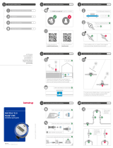
ALWAYS use new gaskets
(PE or EPDM).
The sealing surface of
the threaded connection
must be clean and level.
The piping must be parallel and match the meter.
flowIQ® 3100
Installation guide
Kamstrup A/S • 55121182_C1_GB_08.2021
Kamstrup A/S · Industrivej 28, Stilling · DK-8660 Skanderborg
T: +45 89 93 10 00 · F: +45 89 93 10 01 · [email protected]
Optical eye for reading and configuration
Graphical flow indicator
Type number
(includes information on meter size, overall
length etc.)
Serial number and production year
Configuration
(with information on display resolution
and encryption level etc.)
Accuracy class 2 according to OIML R49,
Electrical E2 and Mechanical M1 according to MID,
ambient class B and C according to OIML R49
(indoors/outdoors)
Customer label, e.g. water utility logo or the meter serial no.
Bar code with serial number
Expiry year of battery
Temperature class according to OIML R49
Meter size Q3
Software version and dynamic range
Pressure stage and protection class
CE-marking according to MID

1.4 Straight inlet
flowIQ® 3100 requires neither straight inlet nor straight outlet to meet
the Measuring Instruments Directive (MID) 2004/22/EC and OIML R49.
A straight inlet section will only be necessary in case of heavy flow
disturbances before the meter.
1.5 Operating pressure
In order to avoid cavitation and secure correct measurement under all
conditions, the operating pressure in the pipe system must observe
the test conditions of OIML R49, which means that the static pressure
immediately after the meter (downstream) must always be minimum
0.03 MPa (0.3 bar), for DN50 it must always be minimun 0.2 MPa (2 bar).
1.2 Installation requirements
flowIQ® 3100 has built-in data communication, which enables remote
reading of the meter. If installed in pits or basements, the meter must
in some cases be fitted with an external antenna in order to secure
optimum communication. The antenna must be placed outside pit or
basement.
Prior to installation of flowIQ® 3100 the system should be flushed while
a fitting piece replaces the meter.
Please check that stop valves are tight and operate as intended and
that the pipe system is without corrosion and damages. Damaged
components, if any, must be replaced.
Close the main stop valve in front of the meter and let a tap run until the
pressure in the system has been equalized. Close the stop valve after
the meter before disassembling the pipe system.
Having assembled the pipe system, all sealing surfaces of existing
couplings must be cleaned to remove possible remaining pieces of
gasket. Remove adhesive wafers from the meter’s inlet and outlet and
mount the meter. Always use new gaskets in original quality.
The flow direction is indicated by an arrow on the side of the meter.
Install the meter with an orientation that makes it easy for the
consumer to read the display.
During installation it must be secured that the meter is mounted
without mechanical bias in the connection pipes. Do not attempt to
correct oblique piping by means of the meter.
At the same time make sure that the threaded length of the couplings
does not prevent proper tightening of the sealing surface and that PN10
or PN16 couplings are used.
If meters are mounted in meter wells or outdoors, both the meter well
and the meter must be protected against freezing.
Thread meters – sizes 4.0, 6.3 and 10.0 m3/h of the flowIQ® 3100
series – are prepared for mounting of a coarse-mesh strainer (filter) in
the meter’s inlet connection. Furthermore, a nonreturn valve can be
mounted in the meter’s outlet connection.
Service
When the meter has been mounted in the system neither welding nor
freezing is allowed. Dismount the meter from the system before starting
such work.
In order to facilitate replacement of the meter, closing valves should be
mounted on either side of the meter.
Under normal operating conditions no pipe strainer is required in front of
the meter. Nonreturn valves must be mounted in accordance with local
regulations.
1.3 Installation angle of flowIQ® 3100
flowIQ® 3100 can be mounted at all angles and positions. Kamstrup
A/S recommend that the display is mounted so that it is easy to read, if
possible.
Thus, the meter can be mounted in a usual horizontal installation. It can
be mounted vertically on an ascending pipe, it can be mounted at any
angle and it can be mounted with its display pointing downwards, e.g
under a roof.
A
B
C
D
A Recommended water meter position.
B Recommended water meter position.
C Used for “well installation”. Air build-up may occur.
D The meter functions optimally, but the display is “upside down”.
1 General information
Read this guide before installing the water meter.
flowIQ® 3100 is a compact electronic water meter used for water
consumption measurement in the tap water supply of homes,
commercial and industrial buildings. The meter is watertight and thus
well suited for mounting in small pump stations and meter wells, which
are frequently filled with water. flowIQ® 3100 has been constructed for
maintenance-free operation for up to 16 years.
flowIQ® 3100 is hermetically closed, and it is, therefore, not possible
to service, the meter without breaking the seal. This means that all
service including battery change, must be carried out by an authorized
Kamstrup Service Centre.
Certain changes of configuration, however, are possible via the built-in
optical eye without dismounting the meter from the installation. Further
details appear from data sheet and technical description.
1.1 Permissible operating conditions / measuring
ranges
Temperature of medium
water meter: 0.1 °C...50 °C
Pressure stage: PN16
Mechanical environment: M1 (MID) Fixed installation with minimum
vibration.
Electromagnetic
environmental class: E1 and E2 (MID).
Housing and trade.
Protection class: IP68
Climatic environment: 2 °C...55 °C. Condensing humidity.
(indoors mounted in utility rooms and
outdoors in meter wells). Installation in
direct sunlight ought to be avoided.
1.6 Info codes and display
When flowIQ® 3100 leaves Kamstrup A/S, it has been tested and
verified and the counter has been reset.
M3 are displayed by five big digits. The small digits are decimals after
the dot.
A number of info codes can be displayed, of which DRY and RADIO OFF
will be activated and will flash upon delivery. Furthermore, the two small
squares in the bottom right-hand corner will flash to indicate that the
meter is active.
Info code DRY indicates that there is air in the meter, the info code
disappears when the meter is water-filled. As long as the meter is not
water-filled nothing is measured. Blowing through the meter with air
does not influence the meter either.
The info code RADIO OFF indicates that the meter is still in transport
mode with the built-in radio transmitter turned off. The transmitter
turns on automatically when the first litre of water has run through the
meter. The radio transmitter remains on, and the info code signal in the
display switches off.
The flow arrows in the left side of the display indicate water flow through
the meter. If the water is stagnant, all arrows will be off.
The table below describes the different info codes in the display.
The figure after the ”A” indicates how many times the meter has been
adjusted or reset. In a completely new meter both of these indicators
will be switched off.
Laboratories which have reverified and adjusted or reset the meter, shall
attach a label with information on the valid adjustment number to the
meter.
Info code flashes in
display
Meaning
LEAK During the latest 24 hours the water in the
meter has not been stagnant for minimum
one continuous hour.
This can indicate a leakage in the pipe
system.
BURST The water flow has exceeded a
preprogrammed limit for minimum 30
minutes which is a sign of a burst pipe.
TAMPER Tampering attempt. The meter is no longer
valid for billing purposes.
DRY The meter is not water-filled.
REVERSE The water flows in the wrong direction
through the meter.
RADIO OFF The meter is still in transport mode with
the built-in radio transmitter turned off.
The transmitter turns on automatically
when the first litre of water has run
through the meter.
■■ (two square ’dots’) Two small squares that flash alternately
indicate that the meter is active.
/