
INSTALLATION INSTRUCTIONS
INSTRUCCIONES DE INSTALACIÓN
VANITY/0418
READ THESE INSTRUCTIONS COMPLETELY PRIOR TO BEGINNING THE INSTALLATION.
Lee todas las instrucciones antes de comenzar la instalación.
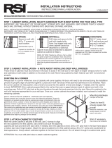
If you are combining cabinets using a 12" drawer base,
there may be instances where the vanity bowl will conict
with the top drawer. Please see section below, VANITY
SINK BOWL AND DRAWER CONFLICT.
TIP: Whenever drilling into a cabinet frame, back panel, wall
cleat, etc., it is recommended to pre-drill a pilot hole rst to
help prevent splitting.
Si estás combinando gabinetes con una base de cajón de 30.5 cm, puede
que en ocasiones el tazón del tocador interera con el cajón superior.
Consulta la sección más abajo, INTERFERENCIA DEL TAZÓN DEL
LAVAMANOS DEL TOCADOR CON EL CAJÓN.
CONSEJO: Siempre que se taladre en un armazón de gabinete, panel
posterior, listón de pared, etc., se recomienda pretaladrar un oricio piloto
para evitar astilladuras.
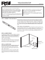
STEP 1: UNEVEN FLOORS AND WALLS
Because oors and walls have uneven spots which will affect the installation,
it will be necessary to locate these uneven areas. Wall and oor unevenness
can cause cabinets to be misaligned resulting in “racking” or misalignment of
the doors and drawer fronts. Uneven spots can be found with a straight edge
or a 4 ft. level. Simply run the straight edge along the oor and wall to identify
any uneven areas. Low spots should be shimmed to ensure all cabinets are
level.
PASO 1: PAREDES Y PISOS DESNIVELADOS
Debido a que los pisos y las paredes tienen áreas desniveladas que afectarán la instalación, será
necesario localizarlas. El desnivel de pisos y paredes puede provocar que los gabinetes no queden
correctamente alineados y traer como consecuencia el “doblamiento” o desalineación de las
puertas y frentes de cajones. Las áreas desniveladas pueden detectarse con un borde recto o con
un nivel de 1.2 m. Sólo pasa el borde recto a lo largo del piso o la pared para identicar cualquier
área desnivelada. Se deben usar cuñas en las áreas hundidas para garantizar que todos los
gabinetes estén nivelados.
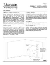
STEP 2: CABINET HEIGHT
To establish the height of your base cabinets, measure
up and mark the wall at 34-1/2 inches from the highest
spot on the oor. Use this mark as a starting point
and draw a level line around the bathroom where the
cabinets will be installed.
PASO 2: ALTURA DEL GABINETE
Para establecer la altura de tus gabinetes base, mide hacia arriba
y haz una marca en la pared a 85.1 cm del punto más alto del piso.
Usa esta marca como punto de partida y dibuja una línea a nivel
alrededor del baño donde se instalarán los gabinetes.
STEP 3: LOCATE STUDS
Locate the wall studs with a stud nder. Mark a chalk
line at the center of the wall's studs at the top and
bottom of the cabinet position. Normally the wall's
studs are located 16" inches apart, center to center.
PASO 3: UBICA LAS VIGAS
Ubica las vigas de pared con el detector correspondiente. Marca
una línea de tiza en el medio de las vigas de pared, en las partes
superior e inferior de la posición del gabinete. Normalmente, las
vigas están ubicadas a 40.6 cm de separación desde el medio de
cada una.
34-1/2"
Level Line
Línea a nivel
Measure 34-1/2"
from high spot
Mide 85.1 cm desde
el punto alto
Cabinet Outlines
Contornos de gabinete
Highest spot on oor
Punto más alto del piso

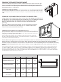
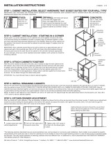
STEP 4: INSTALL BASE CABINETS
When/if your design meets a corner, it is best to start the installation from
that point. If the wall is not straight or plumb, you may need to use a ller
(sold separately); transfer the wall shape to the ller so you can cut the
ller ush to the wall. Fillers may also be used to accommodate wall to
wall installations where the cabinets do not t exactly.
Set the rst cabinet in place and shim it to the previously established level
line. Drill pilot holes at the stud location, through the back panel and into
the studs. Then securely fasten the cabinet to the wall, using #8 X 2-1/2
inch screws and appropriate anchors (DO NOT NAIL). Make sure the
cabinet remains square and level after wall attachment.
PASO 4: INSTALAR LOS GABINETES DE BASE
Cuando/Si tu diseño coincide con una esquina, es mejor comenzar la instalación desde ese
punto. Si la pared no está recta o nivelada, tal vez necesites usar un separador (se vende
por separado) y transferir la forma de la pared al separador para poder recortarlo al ras con
la pared. Los separadores pueden usarse también para adaptar las instalaciones de pared a
pared donde los gabinetes no ajusten con exactitud.
Coloca el primer gabinete en su lugar y cálzalo a la línea a nivel previamente establecida.
Taladra oricios pilotos donde está la viga, a través del riel posterior y dentro de ella.
Enseguida asegura el gabinete a la pared con tornillos núm. 8 de 2/12 pulgadas y los
anclajes apropiados (NO CLAVAR). Verica que el gabinete quede recto y nivelado después
de jarlo a la pared.
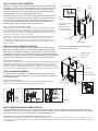
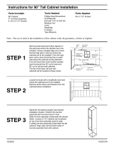
STEP 5: ATTACH CABINETS TOGETHER
Once you have securely fastened the starting cabinet to the wall, line up the
front of the next cabinet and use “C” Clamps to join together. Now drill a pilot
hole using a 1/8" inch drill bit through the adjoining stiles. Once done, draw the
two together, use two #8 X 2-inch wood screws (gure 1). Continue installing the
remaining base cabinets in the same manner. After joining all of your base cabinets
together, verify all cabinets are level; and then secure each cabinet to the wall.
PASO 5: UNIR LOS GABINETES
Una vez que hayas instalado de forma segura el primer gabinete a la pared, alinea la parte frontal del
siguiente y usa las abrazaderas en “C” para unirlos. Ahora taladra un oricio piloto, con una broca
de taladro de 1/8 plg, en los montantes adyacentes. Una vez hecho esto, únelos usando tornillos
para madera núm. 8 de 2 plg (Fig. 1). Continúa instalando los gabinetes restantes de la misma manera.
Después de unir todos tus gabinetes de base, verica que estén nivelados y asegura cada uno a la pared.
STEP 6: HINGE ADJUSTMENT
It usually is necessary to adjust your hinges once you have nished the
installation of your cabinets (gure 2). You must do this before installing any
decorative hardware.
PASO 6: AJUSTE DE BISAGRA
Usualmente es necesario ajustar las bisagras una vez terminada la instalación de tus gabinetes
(Figura 2). Tienes que hacer esto antes de instalar cualquier herraje decorativo.
VANITY SINK BOWL AND DRAWER CONFLICT
If you are combining cabinets using a 12" drawer base, there may be instances where the vanity bowl will conict with the
top drawer. In this case, you will need to remove the top drawer front from the drawer box and mount it directly to the cabinet.
It will also be necessary to cut the side panels to accommodate the sink.
INTERFERENCIA DEL TAZÓN DEL LAVAMANOS DEL TOCADOR CON EL CAJÓN
Si estás combinando gabinetes con una base de cajón de 30.5 cm, puede que en ocasiones el tazón del tocador interera con el cajón superior. En este caso
necesitarás quitar la parte frontal superior del cajón de madera e instalarla directamente en el gabinete. También será necesario cortar los paneles laterales para
ajustar el lavamanos.
Installation spacer
Separador de
instalación
Stiles
Montantes
1/8 in. diameter
3.2 mm de diámetro
Scrap blocks
Bloques de recorte
FIGURE 1
FIGURE 2
Shims
Cuñas
Shims / Cuñas
Wall / Pared
3" Filler. Trim to desired
size and shape
Separador de 7.6 cm
Recorta en la forma y
con el tamaño deseados
Block
Bloque
Block / Bloque
Wall
Pared
Filler
Separador
Toe kick not included, but available separately in
all nishes. Ask for KATKX.

REMOVING THE DRAWER FROM THE CABINET
To remove the drawer entirely from the cabinet, extend the drawer to the outer most location (pull
out as far as it will go). Press release levers in opposite directions while pulling drawer out of the
cabinet. The drawer will now be ready to be removed. Lift the drawer away. Place the drawer with
drawer bottom down, on a solid surface.
CÓMO QUITAR EL CAJÓN DEL GABINETE
Para quitar por completo el cajón del gabinete, saca el cajón tan afuera como sea posible (hálalo hasta donde llegue).
Presiona las palancas de desbloqueo en direcciones opuestas mientras sacas el cajón del gabinete. El cajón estará
listo para ser quitado. Levanta y saca el cajón. Coloca el cajón, con su parte inferior hacia abajo, sobre una supercie
sólida.
REMOVING THE DRAWER FRONT ATTACHED TO DRAWER ITSELF
Using a rubber mallet, tap the drawer front off of the drawer, by tapping to the underside of
the drawer face, so as not to damage the front facing piece. Use 3 or 4 good taps to loosen
the drawer from the sides of the drawer box; please use moderation. Once the
drawer is loosened, remove any staples or tap in place so sharp ends aren’t
protruding.
Reattach the drawer front onto the cabinet. You can discard the disassembled
drawer pieces. Locate the small parts bag, with 4 “L” brackets and 8 screws.
These will be used to reattach the drawer front.
CÓMO QUITAR LA PARTE FRONTAL DEL CAJÓN ENGANCHADA A ESTE
Con un mazo de goma, golpea la parte frontal del cajón, por el fondo de la cara, para no dañar la
pieza que mira al frente. Golpea 3 o 4 veces para liberar el cajón de los lados del compartimiento del
cajón; hazlo con moderación. Una vez que el cajón esté suelto, quita cualquier grapa o golpea en el
lugar para que no sobresalga ningún extremo alado.
Vuelve a instalar la parte frontal del cajón en el gabinete. Puedes desechar las partes desarmadas
del cajón. Localiza la pequeña bolsa de piezas, con 4 soportes en forma de “L” y 8 tornillos. Estos se
usarán para volver a jar la parte frontal del cajón.
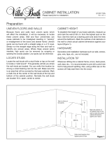
Position drawer front against frame using chart shown below to center it on the frame and line up the drawer front with drawers
below; the chart is based on nish/style of cabinet. Mark equidistant locations on back of drawer front and corresponding
locations on frame for L brackets. Pre-drill 4 holes in the cabinet frame. Drill corresponding holes in back of drawer front, being
careful not to drill through the drawer front. Attach L brackets to frame using provided screws; then attach drawer front to L
bracket.
Coloca la parte frontal del cajón contra el marco usando la tabla que se muestra a continuaciónpara centrar aquel en el marco y alinear la parte frontal con
los cajones más abajo; el gráco se basa en el acabo y estilo del gabinete. Marca posiciones equidistantes en la parte posterior del frente del cajón y las
posiciones correspondientes en el marco para los sujetadores en L. Pre-taladra 4 oricios en el marco del gabinete. Taladra los oricios correspondientes
en la parte posterior del frente del cajón y cuida de no taladrar a través de dicho frente.Engancha los soportes en L al marco con los tornillos suministrados;
enseguida engancha el frente del cajón a los soportes en L.
X X
Y
DRAWER REVEALS
FINISH
X (millimeters) X (inches) Y (millimeters) Y (inches)
MO (RAISED PANEL)
25.4 1 31.2
1 1/4
COG (RAISED PANEL)
25.4 1 31.2
1 1/4
SW (WHITE)
6.4
1/4
6.4
1/4
SJM (SHAKER)
6.4
1/4
6.4
1/4
DRAWER REVEALS / DRAWER REVEALS / DRAWER REVEALS
FINISH / FINISH / FINISH X (millimeters) X (inches) Y (millimeters) Y (inches)
MEDIUM OAK (RAISED PANEL) 25.4 1 31.2 1 1/4
COGNAC (RAISED PANEL) 25.4 1 31.2 1 1/4
SATIN WHITE 6.4 1/4 6.4 1/4
JAVA (SHAKER) 6.4 1/4 6.4 1/4

RSI Home Products • 400 E. Orangethorpe Avenue • Anaheim, CA 92801 • 1-888-578-4009
04/18
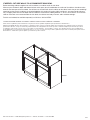
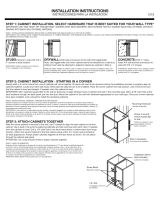
IF NEEDED: CUT SIDE WALLS TO ACCOMMODATE SINK BOWL
Before attaching cabinets together for wall installation, cut cabinet walls for sink base.
Measure your sink bowl’s depth and determine how much space you will need below the surface of the cabinets in order to make
room for the lower part of the sink bowl. You will then cut the side walls of each cabinet on the side of each that you are combining/
attaching (so that when the cabinets are attached together this section will not be visible) see gure 1; we recommend cutting an
arc just slightly more than the full depth and circumference measurement, adding between ½" and 1" for clearance. Once the two
cabinets have been cut to accommodate the sink bowl, the cabinets are ready to attach, and installation to begin.
Toe kick not included, but available separately in all nishes. Ask for KATKX.
SI FUERA NECESARIO: RECORTA LAS PAREDES LATERALES PARA AJUSTAR EL TAZÓN DEL LAVAMANOS
Antes de unir los gabinetes para la instalación en la pared, recorta las paredes de gabinete para ajustar la base del lavamanos.
Mide la profundidad del tazón de tu lavamanos y determina cuánto espacio necesitarás debajo de la supercie de los gabinetes para que quepa la
parte inferior del tazón. Luego recortarás las paredes laterales de cada gabinete en el lado que estés combinando/jando (de forma tal que cuando
los gabinetes estén unidos, esta sección no sea visible); consulta la gura 1; recomendamos cortar un arco ligeramente mayor que la medida de la
profundidad total y la circunferencia, agregando entre 1.3 cm y 2.5 cm más. Una vez que ambos gabinetes hayan sido recortados para ajustar el tazón
del lavamanos, estarán listos para ser jados y la instalación podrá comenzar
FIGURE 1
-
 1
1
-
 2
2
-
 3
3
-
 4
4


Ask a question and I''ll find the answer in the document
Finding information in a document is now easier with AI
in other languages
- español: RCI KATKX-JM Guía de instalación
Other documents
-
 Hampton Bay KSB36-SDV Installation guide
-
Hampton Bay KW361224-MO Installation guide
-
 Hampton Bay KAFS330-CHR Installation guide
-
DANCO 88735 User manual
-
Hampton Bay KW1530-UFDF Installation guide
-
 Hampton Bay KW3624-SW Installation guide
-
 Hampton Bay KSBF60-UF Operating instructions
-
 MasterBath ED12-OTOS Installation guide
-
 Diamond NOW 36 U18R Installation guide
-
 VILLA BATH by RSI LVS36TV2F-COG Installation guide


