Mytek Digital 8X192 ADDA User manual

Category
Headphone amplifiers
Type
User manual

This manual is also suitable for

8 CHANNEL MASTERING ANALOG TO DIGITAL
AND DIGITAL TO ANALOG CONVERTER
USER MANUAL
8X192 ADDA
VER.FEB/2006
2
This manual may be updated
Download the newest version at:
For technical support, technical tips and support check:
or contact Mytek tech support at:
or at:
tel. (646)-613 1822
fax.(212)-202 5331
Mytek
151 Lafayette Street 3rd Fl
New York NY 10013
USA
http://www.mytekdigital.com/manuals/8x192adda_manual.pdf
http://www.mytekdigital.com/products/8x192adda.htm
OWNER’S RECORD:
The serial number is located on the bottom of the unit. We suggest you record the
serial number in the space provided below. The firmware version label is located on
the 8 pin emprom chip located in a socket under the top lid. The firmware can be
updated and chip replaced by the user if necessary. Please be sure to return your
completed warranty card.
8x192 ADDA Serial NO.:
Firmware Version:
Purchase Date:
Dealer/ Contact:
Cards Installed, Serial ##
WARRANTY
This 8X192ADDA digital audio converter is warranted by Mytek to the original
purchaser against defects in workmanship and materials used in manufacture for a
period of one year from the date of purchase. Faults due to customer misuse,
unauthorized modifications or accidents are not covered by this warranty.
No other warranty is expressed or implied.
Any faulty unit should be sent, shipping prepaid, to the manufacturer service center.
Prior to shipping the client should obtain from Mytek an RMA# for warranty services.
Units sent without RMA# will not be accepted.
Mytek extends affordable repair service for all units manufactured to date that are
not covered by this Warranty.
3
Introduction.....................................................…………………………….5
Block Schematics...........................................................................……...7
Back Panel Connections, Cable Wiring.........................................……...8
Front Panel Controls................................................……………...………9
Input/output Gain and other internal adjustments.....……......................10
Signal Flow...............................…………………………………….............6
Setting Clocks and Signal Sources................................................…....12
Specifications............................................................................…..........16
4
Mytek 8X192 ADDA is an 8 channel Analog to Digital and an 8 channel Digital to Analog
converter maticoulsly designed to provide the highest quality signal path. No compromises
have been made to sound quality, and we feel that this is the best sounding Mytek
converter to date. In trial tests in comparison with other hi-end brands this unit provided the
same or better sonic performance, which makes it suitable for the most demanding
mastering and recording applications.
Users choose Mytek converters primarily for their outstanding sonic quality. The sound of
Mytek converters can best be described as "transparent". We design our converters to be
as faithful to the original signal as possible, rather than adhering the philosophy of some
other manufacturers who offer "analog" or "tube" sounding converters. Mytek converters are
designed to be as close to a straight wire as possible,which is especially evident when used
at full 24/192 or DSD resolution.
On the Mytek website you can find and download various sound samples to evaluate the
8X192's sound quality and compare it to the sound of other high end converter units. Please
log onto: http://www.mytekdigital.com to download samples. Thanks to the wide choice of
daughter interface cards (DIO Cards), the 8X192 becomes an 8 channel "digital swiss army
knife",which allows the user to adapt converter performance to most studio setups and
situations."
In addition to typical converter functions, the Mytek 8X192 features a unique analog mix bus
designed with transparency in mind, a monitor section with a mastering grade stepped
attenuator, and a hi-end headphone amp.
The built in CX 797 clock generator with multiple wordclock outputs is
the best source for stable studio house clock, and the 8x192 will perform
best using this internal clock.
5
INTRODUCTION
SIGNAL FLOW
The 8X192 ADDA has two independent signal paths within the unit. They offer independent
signal paths but must operate at the same clock source and sampling frequency. It's
recommended that as much as possible the unit should be clocked from its internal CX 797
clock generator. This mode offers minimum jitter allowin for the best performance and
system stability. Associated equipment should be slaved to 8X192 clock outputs whenever
possible. There is no measurable improvement (rather typically a degradation) when the
unit is clocked by external clock generator.
1) The first path is built around the ADC converter and essentially defines what input is
selected to be sent to digital outputs. All digital outputs are simultaneous, so if the analog
input is engaged, the analog signal is converted to digital and sent to all installed digital
outputs.
If the digital input is selected, only digital format conversion is performed, and the signal is
then passed to the digital outputs. There is no SRC or any kind of digital processing
induced. When operating in DSD mode only the inputs and outputs compatible with DSD
format are active.
"2) The second signal path is built around the DAC. It defines what signal is present at the
analog outputs. The selected digital signal is converted to analog. If the analog input is
selected, it's first converted to digital by the ADC and then sent to the DAC and converted
back to analog.
ANALOG IN
AES/EBU IN
DIOCARD1 IN
DIOCARD2 IN
ADC
TO ALL DIGITAL OUTS
PATH #1
SELECTOR
"INPUT TO
DIGITAL OUTS"
AES/EBU IN
"ANALOG IN"
DIOCARD1 IN
DIOCARD2 IN
DAC
TO 8 DISCRETE
ANALOG OUTS
PATH #2
SELECTOR
"INPUT TO
ANALOG OUTS"
STEPPED
1dB
ATTENUATOR
HEADPHONE
AMP
STEREO
XLROUTS
LEFT
RIGHT
SUMM.
BUS/ PAIR
MONITOR
SELECTOR
6
OPTIONAL DIO CARD #2
PROTOOLS HD, FIREWIRE,
ADAT, TDIF, DSD, SONIC HD
CARDS ARE AVAILABLE
OPTIONAL DIO CARD #1
PROTOOLS HD, FIREWIRE,
ADAT, TDIF, DSD, SONIC HD
CARDS ARE AVAILABLE
115V/230V
SWITCH
LEFT
STEREO ANALOG OUT
RIGHT
WWW.MYTEKDIGITAL.COM
WCK IN
MULTIPLE WCK OUTS
CAUTION! LINE VOLTAGE INSIDE!
AN.OUT 1-8 (TOP)
AN. IN 1-8 (BOTT)
AES/EBU DIO 1-8
THIS UNIT MAY BE OPENED BY QUALIFIED PERSONNEL ONLY!
FUSE 3 AMP SLOW BLOW
ADC 1
VAR.GAIN
(UNDER
HOOD)
FIXED GAIN
-15dBFS
(DEFAULT)
JUMPER
ADC 2
VAR.GAIN
(UNDER
HOOD)
FIXED GAIN
-15dBFS
(DEFAULT)
JUMPER
ADC 3
VAR.GAIN
(UNDER
HOOD)
FIXED GAIN
-15dBFS
(DEFAULT)
JUMPER
ADC 4
VAR.GAIN
(UNDER
HOOD)
FIXED GAIN
-15dBFS
(DEFAULT)
JUMPER
ADC 5
VAR.GAIN
(UNDER
HOOD)
FIXED GAIN
-15dBFS
(DEFAULT)
JUMPER
ADC 6
VAR.GAIN
(UNDER
HOOD)
FIXED GAIN
-15dBFS
(DEFAULT)
JUMPER
ADC 7
VAR.GAIN
(UNDER
HOOD)
FIXED GAIN
-15dBFS
(DEFAULT)
JUMPER
ADC 8
VAR.GAIN
(UNDER
HOOD)
FIXED GAIN
-15dBFS
(DEFAULT)
JUMPER
STEPPED
1dB
ATTENUATOR
HEADPHONE
AMP
DAC 1
VAR.GAIN
(UNDER
HOOD)
FIXED GAIN
-15dBFS
(DEFAULT)
JUMPER
DAC 2
VAR.GAIN
(UNDER
HOOD)
FIXED GAIN
-15dBFS
(DEFAULT)
JUMPER
DAC 3
VAR.GAIN
(UNDER
HOOD)
FIXED GAIN
-15dBFS
(DEFAULT)
JUMPER
DAC 4
VAR.GAIN
(UNDER
HOOD)
FIXED GAIN
-15dBFS
(DEFAULT)
JUMPER
DAC 5
VAR.GAIN
(UNDER
HOOD)
FIXED GAIN
-15dBFS
(DEFAULT)
JUMPER
DAC 6
VAR.GAIN
(UNDER
HOOD)
FIXED GAIN
-15dBFS
(DEFAULT)
JUMPER
DAC 7
VAR.GAIN
(UNDER
HOOD)
FIXED GAIN
-15dBFS
(DEFAULT)
JUMPER
DAC 8
VAR.GAIN
(UNDER
HOOD)
FIXED GAIN
-15dBFS
(DEFAULT)
JUMPER
INPUTS 1-8
OUTPUTS 1-8
CONTROL AND
ROUTING
LOGIC
USER
REPLACEABLE
FIRMWARE
EPROM IN
SOCKET
CX-797
CLOCK
GENERATOR
SUMM.
BUS/ PAIR
MONITOR
SELECTOR
BLOCK SCHEMATIC
7
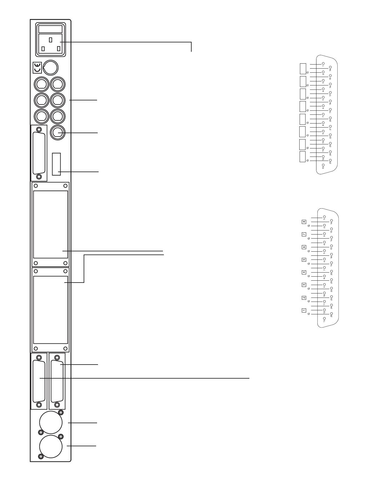
BACK PANEL CONNECTIONS
OPTIONAL DIO CARD #2
PROTOOLS HD, FIREWIRE,
ADAT, TDIF, DSD, SONIC HD
CARDS ARE AVAILABLE
OPTIONAL DIO CARD #1
PROTOOLS HD, FIREWIRE,
ADAT, TDIF, DSD, SONIC HD
CARDS ARE AVAILABLE
115V/230V
SWITCH
LEFT
STEREO ANALOG OUT
RIGHT
WWW.MYTEKDIGITAL.COM
WCK IN
MULTIPLE WCK OUTS
CAUTION! LINE VOLTAGE INSIDE!
AN.OUT 1-8 (TOP)
AN. IN 1-8 (BOTT)
AES/EBU DIO 1-8
THIS UNIT MAY BE OPENED BY QUALIFIED PERSONNEL ONLY!
FUSE 3 AMP SLOW BLOW
Stereo monitor XLR outputs.
Headphone jack present
on front panel
These are +4dB balanced
outputs with 75 Ohm output
impedance. They are buffered
following mix bus/monitor
selector and can be run directly
from bus/selector or via 1dB
precision stepped attenuator by
holding down selector button
until "through knob" led is on.
When driving unbalanced loads
pin 3 should be lifted (not
shorted to gnd). There is no
internal gain adjustment on this
output other than the volume
knob.
features the
same signal as XLR outs but it
is always routed through knob.
Mute switch mutes XLR outs
only.
Discrete 8 analog outputs. These are
direct outputs from each D/A converter.
Since they are not followed by more
electronics they are slightly more
transparent than the monitor outputs and
recommended for use whenever ultimate
transparency is desirable. The outputs are
balanced +4dB and have a set gain of
+4dB=-15dBFS or can be adjusted (see
previous chapter). They have 75 Ohm
output impedance and can drive single
ended (including -10dBV consumer) outputs.
For single ended drive lift all cold signals.
The DB25 pinout is described elsewhere on
this page.
Analog input and output DB25 pinout corresponds to
standard used by Protools, Tascam, Radar and Apogee as
in drawing below. High end versions of DB25 to XLR
breakout cables are available from Mytek, while basic
cables are available through larger music retailers. Note that
all DB25 pinouts including AES DIO are similarly wired with
only difference being the sex of XLR connectors.
AES DIO DB25 pinout
Note , it is different
than Apogee Standard
corresponds to standard used
by Protools as in drawing below.
. High end versions of DB25 to
XLR breakout cables are available from Mytek, while
basic cables are available through larger music
retailers. Note that all DB25 pinouts including AES DIO
are similarly wired with only difference being the sex of
XLR connectors.
Powers supply is an oversized linear type and has to
be set for appriopriate line voltage by the user using the
round switch. The fuse is 20 mm 3Amp SLOW BLOW
type and can be replaced by lifting the module next to
power cord receptacle.
Discrete 8 analog inputs. These are direct
inputs to each A/D converter. The inputs are
balanced +4dB and have a set gain of
+4dB=-15dBFS or can be adjusted (see
previous chapter). They have 10 kOhm input
impedance and can be driven by single
ended sources (including -10dBV
consumer). The DB25 pinout is described
elsewhere on this page.
DIP Switch enables addtnl special
functions. ON is down OFF is up.
dipsw8 ON: wckin 75 ohm termination
dipsw7 : dual wire - for FSx2 or x4.
dipsw6 : makes BNCs superclock
instead of wordclock.
ON
ON
Internal hi-performance
features one wordclock
input (TTL or 3-5V) which can be
terminated (see DIP switch). It can be
multiplied if necessary by switch on
front panel. There are also multiple
wordclock outputs for synchronizing
the rest of studio to the 8X192 ADDA.
Both in and outs can also be Protools
Superclock
(256x FS) (see DIP switch).
CX 797 Clock
Generator
Two optional DIOCARD slots. Up two two extra digital interfaces can
be installed for formats stated on the back of the slot. These cards can
be installed by user without voiding the warranty, providing the
connecting ribbon is properly insterted on both ends. To install the card:
Power down, remove top unit cover and the back small slot cover.
Secure the card with 4 screws and connect short ribbon straight to
motherboard (without twisting the cable). Make sure all pins match the
connector properly. Power up- once card is identified by system, it will
become accessible from front panel.
DSD DIOCard additionally to providing DSD I/O will also load the DSD
firmware into the unit thus enabling DSD conversion.
-
+
-
+
-
+
-
+
-
+
-
+
-
+
-
+
-
+
-
+
-
+
-
+
-
+
-
+
-
+
-
+
IN1-2
IN3-4
IN5-6
IN7-8
OUT1-2
OUT3-4
OUT5-6
OUT7-8
8
FRONT PANEL CONTROLS
DSD and 128xDSD
(hi-speed) feature
can be enabled by
installing the DSD
DIOCARD.
Pressing and holding
button
enables or disables
external sync. Toggling
this switch selects the
source of external clock.
Ext.Clock Source
WCK switch allows
wordclock (both in and
out) to be a division of
sampling frequency.
For example- when
FS/4 is selected, the
converter will operate
at FS=176.4k while the
wordclock is 44.1k.
Source to Digital
Out- See Signal
Flow on pg 6.
Source to Analog
Out- See Signal
Flow on pg 6.
Meters- Selects
signal displayed
by Meters- either
ADC or DAC.
Red meter LED
is a full scale
signal at 1
sample or more.
We do not
recommend
peaking at red.
Stereo Output selector determines
what is present on stereo XLR
outputs and headphone. It can
either be any pair of DACs or L/R
sum of them (odd channels
summed to L and even to R) or
Mono sum of all 8 chan.
Holding this button selects Thru
Knob function which routes the
XLR output via volume attenuator.
These outputs are typically
connected directly to power amp or
powered speakers providing hi-
fidelity short signal monitor path.
Hi- Fidelity, high drive
headphone out can drive any
type of headphones with
ultimate fidelity. It's able to
provide up to 1 Amp of instant
current drive. The headphone
out is the same as XLR and
it's always routed through the
knob.
Precision 1dB steeped
attenuator features a
precision 24 step switch and
precision resistor ladder
resulting in very accurate
level monitoring for mastering
purposes.
Mute button mutes
main XLR outs.
Sample Rate switch
toggles btwn sampling rates
for PCM and if DSD option
is installed, sets the unit to
DSD or 128xDSD mode.
This switch sets sample
rate for both AD and DA
and has to be set manually
even if ext. clock is applied.
In such case it has to be the
nearest approximation of
applied clock (or its
multiplication if FS/2 or
FS/4 is selected).
9
INPUT/OUTPUT GAIN
AND OTHER INTERNAL ADJUSTMENTS
Analog input/output alingment
The 8X192 ADDA analog input/output sensitivity comes as factory default fixed at -15dBFs
corresponding to +4dB (OVU=1.228VRMS measured between hot and cold). This gain is
optimal for most situations and unless another level "is necessary for systemic reasons, we
recommend leaving the gain at the default setting. If the gain has to be changed the
appriopriate jumpers and trimpots have to be accessed by lifting the top cover. Please
review the drawing on following page.
The gain alignment does not affect audio quality, only input/output sensitivity. A small
tweaker or screwdriver is necessary. First you have to arbitrarily decide what will be your
studio "0 VU" analog/digital reference level. It is usually between -20 and -14dB. It defines
how much headroom is left over the normal operating "0 VU" level. You may set it at the
same level as other piece of equipment in your studio.
Step 1 - Analog output alignment
Step 2 - Analog input alingment
1. Play a digital audio source (DAW generator, test CD etc.) set to approx. 1kHz at the peak
operating level you have chosen (let's say you have chosen -18dB).
2. Send the signal from the analog output to the console VU meter. If you don't have a VU
meter you can use an AC voltmeter set to measure AC RMS values. "0 VU"at + 4dB
corresponds to 1.225 Volts RMS measured between pin hot and pin cold of the output
signal.
3.Using a tweaker or a small screwdriver adjust the analog outputs until the VU meter reads
"0 VU".
4. Repeat the same for all outputs.
1.Set the oscillator in your console at 1kHz and "0 VU". Send the oscillator to the
8X192ADDA analog input."0 VU" at + 4dB corresponds to 1.225 Volts RMS measured
between pin 2 and 3 of the output XLRs. If you do not have an analog oscillator, you can
use a calibrated analog out of a DA converter and generate a sinewave inside the DAW.
Alternatively, if you do not have an oscillator you can use the analog outputs you have just
aligned as a source of a sinewave at +4dB (generating sinewave digitally as in step 1).
2.Select the "analog input". Connect a digital meter to a digital output. If you don't have a
dedicated digital meter use the most precise meter available in you existing digital recording
equipment or DAW.
3. Adjust the analog input level to get appropriate reading of the meter
(for example -18dB).
4. Repeat the same for all of the analog inputs.
10
8X192 FIRMWARE EPROM
USER REPLACEABLE
DAC GAIN ADJUSTMENT JUMPERS AND TRIMPOTS
JUMPERS SET EITHER FIXED +4dB=-15dBFS OR ENABLE
10 TURN TRIMPOTS FOR MANUAL GAIN ADJUSTMENT
DAC#1
JUMPERS TO RIGHT=FIXED -15dB GAIN
JUMPERS TO LEFT= VARIABLE TRIMPOTS
JUMPERS TOWARDS BACK=FIXED -15dB GAIN
JUMPERS TOWARDS FRONT= VARIABLE TRIMPOTS
ADC#2
ADC#4
ADC#3
ADC#6
ADC#5
ADC#8
ADC#7
ADC#1
DAC#5
DAC#3
DAC#7
DAC#2
DAC#6
DAC#4
DAC#8
ADC GAIN ADJUSTMENT JUMPERS AND TRIMPOTS
JUMPERS SET EITHER FIXED +4dB=-15dBFS OR ENABLE
10 TURN TRIMPOTS FOR MANUAL GAIN ADJUSTMENT
DIOCARD1 HEADER
DIOCARD2 HEADER
INTERNAL ADJUSTMENTS
CONTINUED
11
NORMAL OPERATION. AD AND DA ON INTERNAL CLOCK.
AD FEEDING THE RECORDER, DA MONITORING RECORDER
FEED THROUGH OPERATION. AD AND DA ON INTERNAL CLOCK.
AD FEEDING DA DIRECTLY
SETTING CLOCKING AND SIGNAL SOURCES
2.
In this mode both the AD and DA run on the internal clock. This mode provides the lowest jitter and
most sonically robust performance. External recorders (such as DAW etc) have to be synchronized
either to the AD digital outputs (any format: AES or DIOCARD1 or DIOCARD2) or to the
converter Worclock output.
This example shows 44.1 PCM, but any FS can be any selected, including DSD and 128x DSD. Also
instead of AES, any other digital input to DA can be selected, depending on the particular system
configuration. The unit will output on its BNC outs Wordclock corresponding to the sampling
frequency unless it's divided by using WCK button.
If the DA converter receives no selected digital in OR this input is not synchronous with AD clock, the
LED will flash and DA converter will mute."
In this mode both the AD and DA run on the internal clock. This mode also provides the lowest jitter and
most sonically robust performance. External recorders (such as DAW etc) must be synchronized either
to AD digital outputs (any format: AES or DIOCARD1 or DIOCARD2) or to the converter Worclock
output.
In this mode signal is fed from AD to digital outputs and also to DA directly. This mode may be usefull
when conversion latency has to be minimized during the recording. It functionally corresponds to a
multitrack tape machine always on "input". This example shows 44.1 PCM, but any FS can be any
selected, including DSD and 128xDSD. Also instead of AES any other digital input to DA can be
selected depending on particular system configuration. The unit will output on its BNC outs Wordclock
corresponding to the sampling frequency unless it's divided by using WCK button. "
1.
LED ON
LED OFF
LED ON
LED OFF
12
FEED THROUGH OPERATION. AD AND DA ON EXTERNAL CLOCK.
AD FEEDING DA DIRECTLY
4.
In this mode both the AD and DA run on an external clock. Holding the "Ext. Clock Source" button
selects this mode. Although this mode does not provide the lowest jitter performance it might be
desirable for systemic reasons. External recorders (such as DAW etc) can be synchronized to
external wordclock sources OR AD digital outputs (any format: AES or DIOCARD1 or DIOCARD2) OR
to converter Worclock output.
This example shows 44.1 PCM, but any FS can be selected, including DSD and 128xDSD. Also instead
of AES any other digital input to DA can be selected depending on a particular system configuration.
The unit will output on its BNC Wordclock outs corresponding to the sampling frequency provided
externally unless it's divided by using WCK button. If the DA converter receives no selected digital in OR
this input is not synchronous with AD clock, the LED will flash and DA converter will mute. Sample Rate
has to be selected manually to match wck or its nearest approximation. WCK will be the base of
sampling rate. If no WCK source is detected, WCK LED will flash and the unit will not pass signal.
In this mode both the AD and DA run on an external clock. Although this mode does not provides the
lowest jitter performance it might be desirable for systemic reasons. External recorders (such as DAW
etc) can be synchronized to an external wordclock source OR AD digital outputs (any format: AES or
DIOCARD1 or DIOCARD2) OR to a converters Worclock output. In this mode signal is fed from the AD
to digital outputs and also to DA directly. This mode may be useful when conversion latency has to be
minimized during the recording. It functionally corresponds to a multitrack tape machine always being on
"input".
This example shows 44.1 PCM, but any FS can be selected, including DSD and 128xDSD. Also instead
of AES any other digital input to DA can be selected depending on a particular system configuration.
The unit will output on its BNC outs a Wordclock signal corresponding to the sampling frequency
provided externally, unless it's divided by using the WCK button. If the DA converter receives no selected
digital in OR this input is not synchronous with AD clock, the LED will flash and DA
converter will mute. The Sample Rate has to be selected manually to match wck or its nearest
approximation. WCK will be the base of sampling rate.
If no WCK source is detected, the WCK LED will flash and the unit will not pass signal.
NORMAL OPERATION. AD AND DA ON EXTERNAL WORDCLOCK.
AD FEEDING THE RECORDER, DA MONITORING RECORDER
3.
LED ON
LED OFF
LED ON
LED OFF
13
FEED THROUGH OPERATION. AD AND DA ON INTERNAL CLOCK.
AD FEEDING DA DIRECTLY
6.
In this mode both the AD and DA run on an external clock. Although this mode does not provides the
lowest jitter performance it might be desirable for systemic reasons. For example a second 8X192 unit
running can be coupled with a master 8X192 unit via Firewire cable only. In this case the clock for the
second unit is provided via a Firewire card (DIOCARD1 in this example). External recorders (such as
DAW etc) can be either AD digital outputs (any format: AES or DIOCARD1 or DIOCARD2), converter
Worclock outputs, or can run in asynchronous Firewire mode.
This example shows 44.1 PCM, but any FS can be any selected, including DSD and 128xDSD. Also
instead of AES any other digital input to DA can be selected depending on a particular system
configuration.
The unit will output on its BNC outs Wordclock corresponding to the sampling frequency provided
externally unless it's divided by using WCK button. If the DA converter receives no selected digital in OR
this input is not synchronous with AD clock, the LED will flash and DA converter will mute. The Sample
Rate has to be selected manually to match wck or its nearest approximation. WCK will be the base of
sampling rate. If no WCK source is detected, WCK LED will flash and unit will not pass signal.
In this mode both the AD and DA run on an external clock. Although this mode does not provides the
lowest jitter performance it might be desirable for systemic reasons. For example a second 8X192 unit
running can be coupled with a master 8X192 unit via a Firewire cable only. In this case the clock for
second unit is provided via Firewire card (DIOCARD1 in this example). External recorders (such as DAW
etc) can be either AD digital outputs (any format: AES or DIOCARD1 or DIOCARD2), converter Worclock
output, or can run in asynchronous Firewire mode. In this mode signal is fed from AD to digital outputs and
also to DA directly. This mode may be usefull when conversion latency has to be minimized during the
recording. It functionally corresponds to a multitrack tape machine always on"input".
This example shows 44.1 PCM, but any FS can be any selected, including DSD and 128xDSD. Also
instead of AES any other digital input to DA can be selected depending on a particular system
configuration.
The unit will output on its BNC outs Wordclock corresponding to the sampling frequency provided
externally unless it's divided by using WCK button. If the DA converter receives no selected digital in OR
this input is not synchronous with AD clock, the LED will flash and DA converter will mute. The Sample
Rate has to be selected manually to match wck or its nearest approximation. WCK will be the base of
sampling rate. If no WCK source is detected, WCK LED will flash and unit will not pass signal.
NORMAL OPERATION. AD AND DA ON EXTERNAL CLOCK OTHER THAN WCK.
AD FEEDING THE RECORDER, DA MONITORING RECORDER
5.
LED ON
LED OFF
LED ON
LED OFF
14
In this mode the 8X192 unit can be used for format conversion between all installed digital interfaces.
Once a digital input is selected for "SOURCE TO DIGITAL", the "SAMPLE RATE" switch is disabled and
EXT.CLOCK SOURCE and SOURCE TO ANALOG OUT automatically set to selected digital input. The
incoming digital signal is converted to all available digital formats simultanouesly as well as is sent to DA
converter for monitoring. The wck divider affects only WCK outs. WCK is derives from incoming digital
input, in this example DIOCARD1.
ADC IS OFF, DIGITAL IN TO DIGITAL OUT, DA MONITORING DIGITAL IN.
FORMAT CONVERSION OPERATION.
7.
LED ON
LED OFF
15
Specifications ADC*
Specifications DAC
Specifications Other
Conversion: Linear, 1 Bit *
128x oversampling at 44.1-48kHz
64x oversampling at 88.2-192kHz, optional 64xDSD and 128xDSD
Resolution: 24 bit, ( or 1 bit DSD)
Sample rates: 44.1kHz, 48kHz, 88.2kHz, 96kHz, 176.4kHz, 192kHz
or wordclock 25-200kHz
Dynamic Range: 120dB A-weighted, 117dB Total
THD+Noise: -106dB (<0.0005%)
Internal clock jitter: <10picoseconds
Analog Inputs: +4dBm balanced or unbalanced, 10 kOhm
Conversion: Linear, multibit delta-sigma
PCM and 64xDSD and 128xDSD
Resolution: 24 bit, ( or 1 bit DSD)
Sample rates: 44.1kHz, 48kHz, 88.2kHz, 96kHz, 176.4kHz, 192kHz
or wordclock 25-200kHz
Dynamic Range: 123dB A-weighted, 120dB Total
THD+Noise: -110dB (<0.0004%)
Internal clock jitter: <10picoseconds
Analog Outputs:+4dBm balanced or unbalanced, 75 Ohm
Digital outputs: Hi-Speed AES/EBU built in up to 200k or dual wire for 4 chan operation
Other formats on optional DIO Cards
External Sync.: Wordclock in and out.
or 256x Superclock
Wordlock Out
used as house clock: 15 LS TTL loads max. Can be terminated with 75 Ohm. 6 Outs
Wordlock In TTL/5V input- internally switchable termination 75 Ohm.
Wordclock can be replaced by Superclock fiunction
Mains: 100/115V-220/240V 50/60Hz switchable
Weight, Dim:: 14 pounds (7 kg), 1U x 19 inch x 10.5 inch deep
* This ADC uses a 1 bit delta sigma modulator which achieves instristically better low level
linearity than the multibit counterparts. Although multibit ADC THD measurements are marginally
better, the distribution of distortion subjectively sounds less desirable than in 1 bit converter which
tends to exhibit certain silky quality. The same, currently worlds' highest performance 1 bit
modulator is used to produce genuine 1 bit DSD signal.
16
  • Page 1 1
  • Page 2 2
  • Page 3 3
  • Page 4 4
  • Page 5 5
  • Page 6 6
  • Page 7 7
  • Page 8 8
  • Page 9 9
  • Page 10 10
  • Page 11 11
  • Page 12 12
  • Page 13 13
  • Page 14 14
  • Page 15 15
  • Page 16 16
  • Page 17 17

Mytek Digital 8X192 ADDA User manual

Category
Headphone amplifiers
Type
User manual
This manual is also suitable for

Ask a question and I''ll find the answer in the document

Finding information in a document is now easier with AI