
BLACK BOX
®
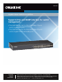
Supports http and SNMP interface for switch
management.
• The LGB2118A has (16) 10-/100-/1000-Mbps TP ports
and (2) Gigabit SFP ports.
• The LGB2124A has (20) 10-/100-/1000-Mbps TP ports
and (4) Gigabit TP/SFP dual-media ports.
Gigabit Smart Switch Eco Fanless
LGB2118A
LGB2124A
Order toll-free in the U.S.: Call 877-877-BBOX (outside U.S. call 724-746-5500)
FREE technical support 24 hours a day, 7 days a week: Call 724-746-5500 or fax 724-746-0746
Mailing address: Black Box Corporation, 1000 Park Drive, Lawrence, PA 15055-1018
Web site: www.blackbox.com • E-mail: info@blackbox.com
Customer
Support
Information

724-746-5500 | blackbox.com
Page 2
Trademarks Used in this Manual
We‘re here to help! If you have any questions about your application
or our products, contact Black Box Tech Support at 724-746-5500
or go to blackbox.com and click on “Talk to Black Box.”
You’ll be live with one of our technical experts in less than 60 seconds.
Trademarks Used in this Manual
Black Box and the Double Diamond logo are registered trademarks of BB Technologies, Inc.
Intel is a registered trademark of Intel Corporation.
Microsoft and Internet Explorer are registered trademarks of Microsoft Corporation.
Novell and NetWare are registered trademarks of Novell, Inc.
Xerox is a registered trademark of Xerox Corporation.
Any other trademarks mentioned in this manual are acknowledged to be the property of the trademark owners.

724-746-5500 | blackbox.com
Page 3
FCC and IC RFI Statements
Federal Communications Commission and Industry Canada Radio Frequency Interference
Statements
This equipment generates, uses, and can radiate radio-frequency energy, and if not installed and used properly, that is, in strict
accordance with the manufacturer’s instructions, may cause inter ference to radio communication. It has been tested and found to
comply with the limits for a Class A computing device in accordance with the specifications in Subpart B of Part 15 of FCC rules,
which are designed to provide reasonable protection against such interference when the equipment is operated in a commercial
environment. Operation of this equipment in a residential area is likely to cause interference, in which case the user at his own
expense will be required to take whatever measures may be necessary to correct the interference.
Changes or modifications not expressly approved by the party responsible for compliance could void the user’s authority to
operate the equipment.
This digital apparatus does not exceed the Class A limits for radio noise emis sion from digital apparatus set out in the Radio
Interference Regulation of Industry Canada.
Le présent appareil numérique n’émet pas de bruits radioélectriques dépassant les limites applicables aux appareils numériques de
la classe A prescrites dans le Règlement sur le brouillage radioélectrique publié par Industrie Canada.
CAUTION:
Circuit devices are sensitive to static electricity, which can damage their delicate electronics. Dry weather conditions or walking
across a carpeted floor may cause you to acquire a static electrical charge.
To protect your device, always: Touch the metal chassis of your computer to ground the static electrical charge before you pick up
the circuit device. Pick up the device by holding it on the left and right edges only.
If you need to connect an outdoor device to this switch with cable, add an arrestor on the cable between the outdoor device and
this switch.

724-746-5500 | blackbox.com
Page 4
NOM Statement
Instrucciones de Seguridad
(Normas Oficiales Mexicanas Electrical Safety Statement)
1. Todas las instrucciones de seguridad y operación deberán ser leídas antes de que el aparato eléctrico sea operado.
2. Las instrucciones de seguridad y operación deberán ser guardadas para referencia futura.
3. Todas las advertencias en el aparato eléctrico y en sus instrucciones de operación deben ser respetadas.
4. Todas las instrucciones de operación y uso deben ser seguidas.
5. El aparato eléctrico no deberá ser usado cerca del agua—por ejemplo, cerca de la tina de baño, lavabo, sótano mojado o cerca
de una alberca, etc.
6. El aparato eléctrico debe ser usado únicamente con carritos o pedestales que sean recomendados por el fabricante.
7. El aparato eléctrico debe ser montado a la pared o al techo sólo como sea recomendado por el fabricante.
8. Servicio—El usuario no debe intentar dar servicio al equipo eléctrico más allá a lo descrito en las instrucciones de operación.
Todo otro servicio deberá ser referido a personal de servicio calificado.
9. El aparato eléctrico debe ser situado de tal manera que su posición no interfiera su uso. La colocación del aparato eléctrico
sobre una cama, sofá, alfombra o superficie similar puede bloquea la ventilación, no se debe colocar en libreros o gabinetes
que impidan el flujo de aire por los orificios de ventilación.
10. El equipo eléctrico deber ser situado fuera del alcance de fuentes de calor como radiadores, registros de calor, estufas u otros
aparatos (incluyendo amplificadores) que producen calor.
11. El aparato eléctrico deberá ser connectado a una fuente de poder sólo del tipo descrito en el instructivo de operación, o como
se indique en el aparato.
12. Precaución debe ser tomada de tal manera que la tierra fisica y la polarización del equipo no sea eliminada.
13. Los cables de la fuente de poder deben ser guiados de tal manera que no sean pisados ni pellizcados por objetos colocados
sobre o contra ellos, poniendo particular atención a los contactos y receptáculos donde salen del aparato.
14. El equipo eléctrico debe ser limpiado únicamente de acuerdo a las recomendaciones del fabricante.
15. En caso de existir, una antena externa deberá ser localizada lejos de las lineas de energia.
16. El cable de corriente deberá ser desconectado del cuando el equipo no sea usado por un largo periodo de tiempo.
17. Cuidado debe ser tomado de tal manera que objectos liquidos no sean derramados sobre la cubierta u orificios de ventilación.
18. Servicio por personal calificado deberá ser provisto cuando:
A: El cable de poder o el contacto ha sido dañado; u
B: Objectos han caído o líquido ha sido derramado dentro del aparato; o
C: El aparato ha sido expuesto a la lluvia; o
D: El aparato parece no operar normalmente o muestra un cambio en su desempeño; o
E: El aparato ha sido tirado o su cubierta ha sido dañada.

724-746-5500 | blackbox.com
Page 5
Table of Contents
Table of Contents
1. Specifications .........................................................................................................................................................................7
1.1 General ..........................................................................................................................................................................7
1.2 Management Software Specifications ...........................................................................................................................8
2. Overview ...............................................................................................................................................................................9
2.1 Introduction ...................................................................................................................................................................9
2.2 Features .........................................................................................................................................................................9
2.3 What’s Included .......................................................................................................................................................... 10
2.4 Hardware Description .................................................................................................................................................. 11
2.4.1 18-Port Gigabit Smart Switch Eco Fanless (LGB2118A) ....................................................................................... 11
2.4.2 24-Port Gigabit Smart Switch Eco Fanless (LGB2124A) ...................................................................................... 12
3. Installation ........................................................................................................................................................................... 15
3.1 Starting Up the Switch ................................................................................................................................................ 15
3.1.1 Hardware and Cable Installation ......................................................................................................................... 15
3.1.2 Cabling Requirements ......................................................................................................................................... 16
3.1.3 Configuring the Management Agent of the Gigabit Smart Switch Eco Fanless ..................................................20
3.1.4 Address Assignment ........................................................................................................................................... 21
3.2 Typical Applications .....................................................................................................................................................24
4. Basic Concepts and Management .......................................................................................................................................27
4.1 Ethernet .......................................................................................................................................................................27
4.2 Logical Link Control (LLC) ............................................................................................................................................ 28
4.3 Media Access Control (MAC) ......................................................................................................................................30
4.3.1 MAC Addressing ................................................................................................................................................30
4.3.2 Ethernet Frame Format .......................................................................................................................................30
4.4 Flow Control ................................................................................................................................................................33
4.5 How Does a Switch Work? ..........................................................................................................................................37
4.6 Virtual LAN ..................................................................................................................................................................38
4.7 Link Aggregation (LGB2118A Only) .............................................................................................................................43
5. Operation of Web-Based Management ..............................................................................................................................45
5.1 Web Management Home Overview ............................................................................................................................45
5.2 Configuration ..............................................................................................................................................................47
5.2.1 System Information .............................................................................................................................................48
5.2.2 Port Configuration .............................................................................................................................................49
5.2.3 VLAN Mode Configuration ................................................................................................................................ 51
5.2.4 VLAN Group Configuration ................................................................................................................................ 51
5.2.5 VLAN Port Isolation Configuration .....................................................................................................................54
5.2.6 Aggregation (LGB2118A Only) ........................................................................................................................... 55
5.2.7 IGMP Snooping ..................................................................................................................................................56
5.2.8 Mirroring Configuration .....................................................................................................................................56
5.2.9 SNMP .................................................................................................................................................................57
5.2.10 Loop Detection ................................................................................................................................................. 59
5.2.11 Broadcast Storm Protection...............................................................................................................................60
5.2.12 Quality of Service (QoS) Configuration .............................................................................................................62
5.3 Monitoring ..................................................................................................................................................................64
5.3.1 Statistics Overview .............................................................................................................................................. 64
5.3.2 Detailed Statistics ...............................................................................................................................................65
5.3.3 IGMP Status .......................................................................................................................................................67

724-746-5500 | blackbox.com
Page 6
Table of Contents
5.3.4 Ping Status .........................................................................................................................................................68
5.4 Maintenance ................................................................................................................................................................69
5.4.1 Warm Restart .....................................................................................................................................................69
5.4.2 Factory Default ................................................................................................................................................... 70
5.4.3 Software Upgrade ..............................................................................................................................................70
5.4.4 Configuration File Transfer .................................................................................................................................70
5.4.5 Logout................................................................................................................................................................ 71
6. Troubleshooting ...................................................................................................................................................................72
6.1 Resolving Line Condition .............................................................................................................................................72
6.2 Questions and Answers ...............................................................................................................................................72
6.3 Contacting Black Box...................................................................................................................................................72
6.4 Shipping and Packaging ..............................................................................................................................................72
Appendix. MIB ..........................................................................................................................................................................73

724-746-5500 | blackbox.com
Page 7
Chapter 1: Specifications
1. Specifications
1.1 General
Aging — Auto-aging with programmable inter-age time
Auto-Negotiation — Supports auto-negotiation for configuring speed and duplex mode
Blocking Prevention — Supports Head of Line (HOL) blocking prevention
Buffer Memory — Embedded 512 KB frame buffer
Cable Type and Maximum Length — Twisted-Pair (TP): CAT5 UTP cable, up to 328 ft. (100 m);
Fiber: 1000BASE-SX: up to 721.7/902.2/1640.4/1804.5 ft. (220/275/500/550 m), depending on multimode fiber type,
1000BASE-LX: Single-mode fiber, up to 6.2/18.6/31.1 mi. (10/30/50 km)
Filtering — Supports broadcast storm filtering
Flow Control — IEEE 802.3x flow control for full-duplex ports; collision-based backpressure for half-duplex ports
Forwarding/Filtering Rate (Packets per Second [PPS]) — 1,488,000 PPS at 1000 Mbps; 148,800 PPS at 100 Mbps;
14,880 PPS at 10 Mbps
MAC Address and Self-learning — 8K MAC address
Management — Web-based management provides the ability to completely manage the switch from any Web browser
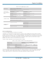
Network Interface —
Table 1-1. Network interface.
Configuraton Mode Connector/Port Number
10/100/1000 Mbps Gigabit TP Auto-negotiation
LGB2118A: TP (RJ-45) 1–16
LGB2124A: TP (RJ-45) 1–24
1000BASE-SX Gigabit fiber 1000 FX
LGB2118A: *SFP 9, 10
LGB2124A: **SFP 21–24
1000BASE-LX Gigabit fiber 1000 FX
LGB2118A: *SFP 9, 10
LGB2124A: **SFP 21–24
NOTE: *Ports 9 and 10 on the LGB2118A SFP fiber ports and **Ports 21–24 on the LGB2124A are TP/SFP fiber dual media ports
with auto detection function. Optional SFP modules support LC transceivers.
Priority Queueing — 802.1p Class of Service with 2-level priority queueing
Programmable Maximum Ethernet Frame Length — 1518 to 9600 bytes jumbo frames
Self-Learning and Address Recognition Mechanism — Enables forwarding rate at wire speed
Sniffer Function — Supported
Standards Compliance — IEEE 802.3/802.3ab/802.3z/802.3u/802.3x, IEEE 802.1ad QinQ;
LGB2118A also has: 802.3ad LACP
Store-and-Forward — Non-blocking store-and-forward shared memory Web Smart switched
Transmission Mode — 10-/100-Mbps support full- or half-duplex, 1000-Mbps support full-duplex only
Transmission Speed — 10-/100/1000-Mbps for TP, 100-/1000-Mbps for Fiber
Trunking — LGB2118A Only: Supports port trunking with flexible load distribution and failover function

724-746-5500 | blackbox.com
Page 8
Chapter 1: Specifications
VLAN — Supports Port-based VLAN and Tag-based (IEEE 802.1Q) VLAN
Connectors — LGB2118A: (16) 10-/100-/1000-Mbps Gigabit Ethernet (TP) switching ports, (2) Gigabit SFP fiber module ports;
LGB2124A: (20) 10-/100-/1000-Mbps Gigabit Ethernet (TP) switching ports, (4) Gigabit TP/SFP fiber dual media ports with
auto detection function
Indicators — LGB2118A: (33) LEDs: (1) System Power, (16) LINK/ACT and (16) SPD LEDs for 10/100/1000 M TP Ports 1 to 16,
(2) LINK/ACT and (2) SPD LEDs for 1000 M SFP fiber Ports 19 to 20;
LGB2124A: (49) LEDs: (1) System Power, (24) LINK/ACT and (24) SPD LEDs for 10/100/1000 M TP Ports 1 to 24, (4) LINK/ACT
and (4) SPD LEDs for 1000 M SFP fiber Ports 21 to 24
Power — Input: 100–240 VAC, 50-60 Hz;
Consumption: 20 W
Ambient Temperature — 32 to 104° F (0 to 40° C)
Humidity Tolerance — 10 to 90%
Size — LGB2118A: 1.45"H x 8.57"W x 5.86"D (3.7 x 21.8 x 14.9 cm);
LGB2124A: 1.7"H x 17.4"W x 6.7"D (4.4 x 44.2 x 17 cm)
Weight — LGB2118A: 4.63 lb. (2.1 kg);
LGB2124A: 5.51 lb. (2.5 kg)
1.2 Management Software Specifications
Bandwidth Control — Supports by-port Egress/Ingress rate control
Quality of Service (QoS) — Referred to as Class of Service (CoS) by the IEEE 802.1P standard
System Configuration — Auto-negotiation support on 10/100/1000BASE-TX ports, Web browser can set transmission speed
(10- /100- /1000-Mbps) and operation mode (Full-/Half-duplex) on each port, enable/disable any port, set VLAN group, set
Trunk Connection
Trunk Function — Port trunk connections allowed
VLAN Function — Port-Base/802.1Q-Tagged, allows up to 10 active VLANs in one switch
Web Browser Support — Based on HTTP Server

724-746-5500 | blackbox.com
Page 9
Chapter 2: Overview
2. Overview
2.1 Introduction
The Gigabit Smart Switch Eco Fanless is a standard switch that meets all IEEE 802.3/u/x/z Gigabit and Fast Ethernet specifications.
The LGB2118A switch has (16) 10-/100-/1000-Mbps TP ports and (2) Gigabit SFP fiber transceiver slots. The LGB2124A switch has
(20) 10/100/1000Mbps TP ports and (4) Gigabit dual media TP/SFP transceiver slots. Both switches support http and SNMP
interfaces for switch management. The network administrator can logon to the switch to monitor, configure, and control each
port’s activity. In addition, the switch implements Quality of Service (QoS), VLAN, and Trunking.
Increase power saving support or reduce power consumption with power management.
The LGB2118A switch’s Ports 17–18 support SFP fiber modules (with LC connectors). The LGB2124A switch’s Ports 21, 22, 23, and
24 include two types of media—TP and SFP Fiber (with LC connectors). The four combo ports on the LGB2124A support
10-/100-/1000-Mbps TP or 1000-Mbps SFP Fiber with auto-detection. A 1000-Mbps SFP Fiber transceiver is used for high-speed
connection expansion.
Table 2-1. 1000-Mbps SFP fiber transceivers.
Product Code Speed Connector/Distance Mode Component
LFP402 1000 Mbps LC, 2 km Multimode, 1300 nm SFP fiber transceiver
LFP401 1000 Mbps LC, 20 km Single-mode, 800 nm SFP fiber transceiver
LFP403 1000 Mbps LC, 40 km Single-mode SFP fiber transceiver
LFP404 1000 Mbps LC, 50 km Single-mode SFP fiber transceiver
10-/100-/1000-Mbps TP is a standard Ethernet port that meets all IEEE 802.3/u/x/z Gigabit, Fast Ethernet specifications. The
1000-Mbps SFP Fiber transceiver is a Gigabit Ethernet port that fully complies with all IEEE 802.3z and 1000BASE-SX/LX
standards.
2.2 Features
The 18- or 24-Port Gigabit Smart Switch Eco Fanless, a standalone off-the-shelf switch, provides the comprehensive features listed
below for users to perform system network administration and efficiently and securely serve your network.
• Quality of Service (QoS): The switch supports 802.1p VLAN tag priority and DSCP on Layer 3 of the network framework.
• VLAN: Supports Port-based VLAN, IEEE 802.1Q Tag VLAN. LGB2118A supports 18 active VLANs and LGB2124A supports 24
active VLANs and VLAN IDs 1–4094.
• Port Trunking (LGB2118A Only): Allows one or more links to be aggregated together to form a link aggregation group by the
static setting.
• Power Saving: The switch uses two proprietary power management techniques that detect when the client is idle and also
detect the cable length automatically. This saves the switch power and reduces the power consumption.
• The LGB2118A has (16) and the LGB2124A has (20) 10-/100-/1000-Mbps Auto-negotiation Gigabit Ethernet TP ports.
• The LGB2118A has (2) SFP fiber module ports and the LGB2124A has (4) 10-/100-/1000-Mbps TP or 1000-Mbps SFP Fiber dual
media autosensing ports.
• Includes 512-KB on-chip frame buffer.
• Supports 9-KB jumbo frames.
• Programmable classifier for QoS (Layer 2/Layer 3).
• Provides 8K MAC address and supports VLAN ID (1–4094).

724-746-5500 | blackbox.com
Page 10
Chapter 2: Overview
• Features per-port shaping, policing, and Broadcast Storm Control.
• Saves power using two proprietary power management techniques.
• Includes IEEE 802.1Q-in-Q nested VLAN support.
• Uses full-duplex flow control (IEEE 802.3x) and half-duplex backpressure.
• Features extensive front-panel diagnostic LEDs: For LGB2118A: System: Power, TP Port 1–16: LINK/ACT, 10-/100-/1000-Mbps,
SFP Port 17 and 18: SFP (LINK/ACT); For LGB2124A: System: Power, TP Port 1–24: LINK/ACT, 10-/100-/1000-Mbps, SFP Port
21, 22, 23, and 24: SFP (LINK/ACT)
• Includes these management features:
- Port status and easy port configuration.
- Per port traffic monitoring counters.
- Provides a snapshot of the system information when you login.
- Port mirror function.
- Static trunk function.
- Supports 802.1Q VLAN.
- Supports user management and limits login to one user.
- Maximum packet length can be up to 9600 bytes for jumbo frame applications.
- Broadcasting Suppression prevents a suspended or crashed network.
- Sends the trap event while monitored events are happening.
- Supports default configuration, which can be restored to overwrite the current configuration via Web UI and/or by pressing the
switch’s Reset button.
- Hot-pluggable SFP modules.
- Supports Quality of Service (QoS) for real-time applications based on the information taken from Layer 2 to Layer 3.
- Use the built-in Web-based management instead of the CLI interface, providing a more convenient GUI for the user.
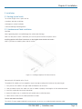
2.3 What’s Included
Before you install the switch, verify that the package contains the following:
• 18- or 24-Port Gigabit Smart Switch Eco Fanless
• Mounting Accessory (for 19" Rack Shelf)
• AC Power Cord
To access this user manual PDF file, go to ftp://ftp.blackbox.com/anonymous/manuals/L/LGB2118A_rev1.pdf
If anything is missing or damaged, contact Black Box Technical Support at 724-746-5500 or info@blackbox.com.
You might also need:
• SFP Modules (optional, LFP401, LPF402, LFB403, or LFP404, described in Table 2-1)

724-746-5500 | blackbox.com
Page 11
Chapter 2: Overview
2.4 Hardware Description
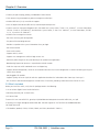
2.4.1 18-Port Gigabit Smart Switch Eco Fanless (LGB2118A)
Figures 2-1 ad 2-2 show the front and back panels of the switch. Table 2-2 describes its components. Table 2-3 describes the LEDs
in detail.
7 1 2 3 4
5 6 8 9
Figure 2-1. LGB2118A front panel.
10
Figure 2-2. LGB2118A back panel.
Table 2-2. LGB2118A components.
Number Component Description
1 (1) Mode button Switches between what is being displayed by LEDs.
2 (16) TP port status LEDs For details, see Table 2-3.
3 (16) TP port speed LEDs For details, see Table 2-3.
4 (2) SFP port status LEDs For details, see Table 2-3.
5 Link/Act LED Lit to show switch is in Link/Act mode.
6 System LED Lit to show switch is in System mode.
7 Speed LED Lit to show switch is in Speed mode.
8 (16) 10/100/1000BASE-T RJ-45 ports 10-/100-/1000-Mbps Ethernet ports
9 (2) 100/1G SFP ports Connect up to two SFP links.
10 (1) AC power socket (on back of unit) IEC-320 power connection.
11 (1) Power LED* (on left side of unit) Lights when power is on.
*Not shown in Figure 2-1 or 2-2.

724-746-5500 | blackbox.com
Page 12
Chapter 2: Overview
Table 2-3. LGB2118A LED functions.
LED Color Function
(1) System Power LED Green Lit when power is on.
(16) LINK/ACT LEDs
Steady green
Blinking green
Lit when connection with remote device is good.
Blinks when any traffic is present.
(16) SPD LEDs
Green
Yellow
Off
Green when TP link is on 1000 Mbps speed.
Yellow when TP link is on 10/100 Mbps speed.
Off when no link is present.
1000SX/LX Gigabit fiber
port 17, 18
(2) LINK/ACT LEDs
Green
Yellow
Off
Green when SFP link is on 1000 Mbps speed.
Yellow when SFP link is on 100 Mbps speed.
Off when no link is present.
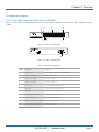
2.4.2 24-Port Gigabit Smart Switch Eco Fanless (LGB2124A)
Figures 2-3 and 2-4 show the front and back panels of the switch. Table 2-4 describes its components. Table 2-5 describes the
LEDs in detail.
7 1 2 3 4
5 6 8 9
Figure 2-3. LGB2124A front panel.
10
Figure 2-4. LGB2124A back panel.

724-746-5500 | blackbox.com
Page 13
Chapter 2: Overview
Table 2-4. LGB2124A components.
Number Component Description
1 (1) Mode button Switches between what is being displayed by LEDs.
2 (24) TP port status LEDs For details, see Table 2-5.
3 (24) TP port speed LEDs For details, see Table 2-5.
4 (4) SFP port status LEDs For details, see Table 2-5.
5 Link/Act LED Lit to show switch is in Link/Act mode.
6 System LED Lit to show switch is in System mode.
7 Speed LED Lit to show switch is in Speed mode.
8 (24) 10 /100/1000BASE-T RJ-45 ports 10-/100-/1000-Mbps Ethernet ports
9 (4) 100/1G SFP ports Connect up to two SFP links.
10 (1) AC power socket (on back of unit) IEC-320 power connection.
11 (1) Power LED* (on left side of unit) Lights when power is on.
*Not shown in Figure 2-3 or 2-4.
Table 2-5. LGB2124A LED functions.
LED Color Function
(1) System Power LED Green Lit when +3.3 V power is on.
(20) LINK/ACT LEDs
Steady green
Blinking green
Lit when connection with remote device is good.
Blinks when any traffic is present.
(20) SPD LEDs
Green
Yellow
Off
Green when TP link is on 1000 Mbps speed
Yellow when T link is on 10/100 Mbps speed.
Off when no link is present.
1000SX/LX Gigabit fiber
port 21, 22, 23, 24
(2) LINK/ACT LEDs
Green
Yellow
Off
Green when SFP link is on 1000 Mbps speed
Yellow when SFP link is on 100 Mbps speed.
Off when no link is present.

724-746-5500 | blackbox.com
Page 14
Chapter 2: Overview
Optional Modules for LGB2118A and LGB2124A
On the LGB2118A switch, Ports 17–18 are SFP fiber module ports. On the LGB2124A, Ports 21–24 include two types of media—
TP and SFP Fiber (with LC connectors); they support 10-/100-/1000-Mbps TP or 1000-Mbps SFP Fiber with auto-detect function.
Use a 1000-Mbps SFP Fiber transceiver for high-speed connection expansion; choose from four optional SFP types listed in Table
2-6.
Table 2-6. Optional modules for LGB2124A.
Product Code Speed Connector/Distance Mode Component
LFP402 1000 Mbps LC, 2 km Multimode, 1300 nm SFP fiber transceiver
LFP401 1000 Mbps LC, 20 km Single-mode, 800 nm SFP fiber transceiver
LFP403 1000 Mbps LC, 40 km Single-mode SFP fiber transceiver
LFP404 1000 Mbps LC, 50 km Single-mode SFP fiber transceiver
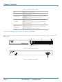
Figure 2-5. Front view of 1000BASE-SX/LX LC, SFP Fiber Transceiver.

724-746-5500 | blackbox.com
Page 15
Chapter 3: Installation
3. Installation
3.1 Starting Up the Switch
This section will give users a quick start for:
• Hardware and cable installation.
• Management station installation.
• Software booting and configuration.
3.1.1 Hardware and Cable Installation
CAUTION:
Wear a grounding device to avoid damage from electrostatic discharge.
Make sure that power switch is OFF before you insert the power cord into the power source.
Installing Optional SFP Fiber Transceivers to the Gigabit Smart Switch Eco Fanless
NOTE: If you have no modules, please skip this section.
Figure 3-1. Installing an optional SFP fiber transceiver.
Connecting the SFP Module to the Chassis:
The optional SFP modules are hot swappable, so you can plug or unplug them before or after powering on.
1. Verify that the SFP module is the right model and conforms to the chassis.
2. Slide the module into the slot. Make sure that the module is properly seated against the slot socket/connector.
3. Install the media cable for network connection.
4. Repeat the above steps, as needed, for each module to be installed into slot(s).
5. Power ON the switch after the above procedures are done.
TP Port and Cable Installation
The switch’s TP ports support MDI/MDI-X auto-crossover, so you can use straight-through or crossover cable.

724-746-5500 | blackbox.com
Page 16
Chapter 3: Installation
Connect CAT5 grade RJ-45 TP cable to a TP port of the switch and connect the other end to a network-aware device such as a
workstation or a server.
Repeat the above steps, as needed, to connect each RJ-45 port to a Gigabit 10/100/1000 TP device.
The switch is ready to operate.
Power On
The switch supports a 100–240 VAC, 50–60 Hz power supply. The power supply will automatically convert the local AC power
source to DC power. The switch‘s ports are hot-swappable, so you can plug in devices or SFPs while the switch is powered on.
After the power is on, all LED indicators will light on and then all will go off except for the power LED, which remains on. This
resets the system.
Firmware Loading
After resetting, the bootloader will load the firmware into the memory. It will take about 30 seconds; after that, all the LEDs on
the switch will flash once while the switch performs a self-test and is ready to use.
3.1.2 Cabling Requirements
For successful installation and good network performance, follow these cabling requirements. Low-quality cables can cause the
switch to malfunction.
Cabling Requirements for TP Ports
For Fast Ethernet TP network connections, use CAT5 or CAT5e cable that’s up to 328 feet (100 m) long.
For Gigabit Ethernet TP network connections, use CAT5 or CAT5e cable that’s up to 328 feet (100 m) long.
We recommend using CAT5e cable.
Cabling Requirements for 1000SX/LX SFP Modules
There are two categories of fiber: multimode (MM) and single-mode (SM). Single-mode cable is categorized into several classes
by the distance it supports. They are SX, LX, LHX, XD, and ZX.
The following table lists the types of fiber that the switch supports. If you don’t see the cable type you need, contact Black Box
Technical Support at 724-746-5500 or info@blackbox.com.

724-746-5500 | blackbox.com
Page 17
Chapter 3: Installation
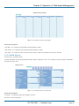
Table 3-1. Fiber supported by the switch.
Fiber cable type Multimode Fiber Cable and Modal Bandwidth
IEEE 802.3z Gigabit
Ethernet 1000BASE-SX,
850 nm
Multimode 62.5-/125-µm Multimode 50-/125-µm
Modal Bandwidth Distance Modal Bandwidth Distance
160 MHz-km 721.7 ft. (220 m) 400 MHz-km 1640.4 ft. (500 m)
200 MHz-km 902.2 ft. (275 m) 500 MHz-km 1804.5 ft. (550 m)
1000BASE-LX/LHX/ZX
Single-mode fiber 9/125 m
Single-mode transceiver 1310 nm, 6.2 mi. (10 km), or 18.6 mi. (30 km)
Single-mode transceiver 1550 nm, 31.1 mi. (50 km)
1000BASE-LX single
fiber (BiDi SC)
Single-mode 12.4 mi. (20 km)
TX (Transmit) 1310 nm
RX (Receive) 1550 nm
Single-mode 12.4 mi. (20 km)
TX (Transmit) 1550 nm
RX (Receive) 1310 nm
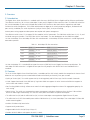
Switch Cascading Topology
The switch cascading topology takes the delay time into account.
Theoretically, the switch partitions the collision domain for each port in switch cascading so that you can uplink an unlimited
number of switches. In practice, the network extension (cascading levels and overall diameter) must follow the constraints of the
IEEE 802.3/802.3u/802.3z and other 802.1 series protocol specifications. The limitations are the timing requirement from physical
signals defined by 802.3 series specification of Media Access Control (MAC) and PHY, and the timer from some OSI layer 2
protocols such as 802.1d, 802.1q, LACP (for LGB2118A only), and so on.
The fiber, TP cables, and devices’ bit-time delay (round trip) are as follows:
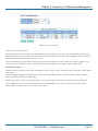
Table 3-2. Fiber, TP cables, and devices’ bit-time delay (round trip).
1000BASE-X TP Fiber 100BASE-TX TP 100BASE-FX Fiber
Round-trip delay: 4096 Round-trip delay: 512
CAT5 TP wire 11.12 / m CAT5 TP wire 1.12 m Fiber cable 1.0/m
Fiber cable 10.10/m TP to fiber converter: 56
Bit time unit 1 ns (1 sec/1000M) Bit time unit: 0.01 s (1 sec/.100 Megabit
The sum of all elements’ bit-time delay and the overall bit-time delay of wires/devices must be within the Round Trip Delay (bit
times) in a half-duplex network segment (collision domain). For full-duplex operation, this does not apply. You may use the
TP-Fiber module to extend the TP node distance over fiber optic and provide the long-haul connection.

724-746-5500 | blackbox.com
Page 18
Chapter 3: Installation
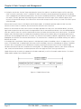
Typical Network Topology in Deployment
A hierarchical network with minimum levels of switches may reduce the timing delay between the server and the client station.
This approach will minimize the number of switches in any one path, lower the possibility of network loops, and improve network
efficiency. If more than two switches are connected in the same network, select one switch as the Level 1 switch and connect all
other switches to it at Level 2. We recommend connecting the Server/Host to the Level 1 switch. This is general advice if no VLAN
or other special requirements apply.
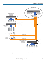
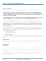
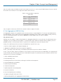
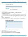
Case 1: All switch ports are in the same local area network. Every port can access each other (see Figure 3-2).
Figure 3-2. No VLAN configuration diagram.
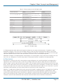
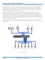
If a VLAN is enabled and configured, each node in the network that can communicate with each other directly is bounded in the
same VLAN area.
Here, VLAN area is defined by what VLAN you are using. The switch supports both port-based VLAN and tag-based VLAN. They
are different in practical deployment, especially in physical location. See Figure 3-3.
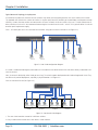
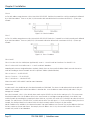
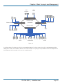
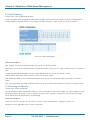
Case 2a: Port-based VLAN (See Figure 3-3).
VLAN 1 VLAN 2 VLAN 3 VLAN 4
Figure 3-3. Port-based VLAN diagram.
1. The same VLAN members cannot be in different switches.
2. Every VLAN member cannot access each other’s VLAN members.

724-746-5500 | blackbox.com
Page 19
Chapter 3: Installation
3. The switch manager has to assign different names for each VLAN group at one switch.
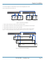
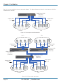
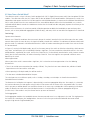
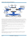
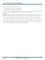
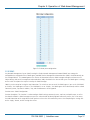
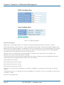
Case 2b: Port-based VLAN (See Figure 3-4).
VLAN 1 VLAN 2 VLAN 3 VLAN 4
Figure 3-4. Port-based VLAN diagram.
1. VLAN1 members cannot access VLAN2, VLAN3, and VLAN4 members.
2. VLAN2 members cannot access VLAN1 and VLAN3 members, but they could access VLAN4 members.
3. VLAN3 members cannot access VLAN1, VLAN2, and VLAN4.
4. VLAN4 members cannot access VLAN1 and VLAN3 members, but they can access VLAN2 members.
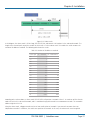
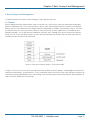
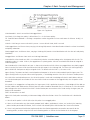
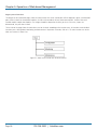
Case 3a: The same VLAN members can be at different switches with the same VID. (See Figure 3-5).
VLAN 1
VLAN 2
VLAN 3
Figure 3-5. Attribute-based VLAN diagram.

724-746-5500 | blackbox.com
Page 20
Chapter 3: Installation
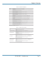
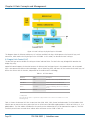
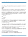
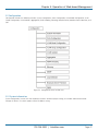
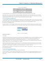
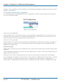
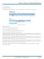
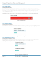
3.1.3 Configuring the Management Agent of the Gigabit Smart Switch Eco Fanless
Via the Web, the switch can set up the management function. Use any one of them to monitor and configure the switch.
Configuring the Management Agent of the Gigabit Smart Switch Eco Fanless through the Ethernet Port
There are two ways to configure and monitor the switch through the switch’s Ethernet port. They are Web browser and SNMP
manager. The user interface for the SNMP manager is management software-dependent and is not described in this manual.
Using the Web-based UI for the switch is described here.
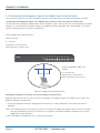
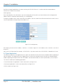
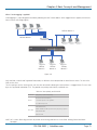
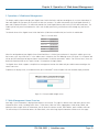
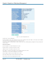
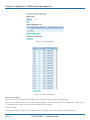
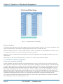
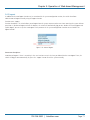
24-Port Gigabit Smart Switch Eco Fanless
Default IP setting:
IP = 192.168.1.1
Subnet Mask = 255.255.255.0
Default Gateway = 192.168.1.254
Ethernet LAN
Assign a reasonable IP address, for
example:
IP = 192.168.1.100
Subnet Mask = 255.255.255.0
Default Gateway = 192.168.1.254
Figure 3-6. Gigabit Smart Switch Eco Fanless.
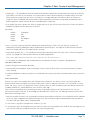
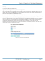
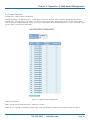
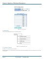
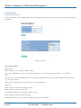
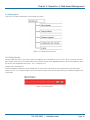
Managing the Gigabit Smart Switch Eco Fanless through the Ethernet Port
Before you communicate with the switch, you must first configure its IP address or know the IP address of the switch. Then,
follow the procedures described next.
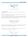
1. Set up a physical path between the configured the switch and a PC, using a qualified UTP CAT5 cable with an RJ-45
connector.
NOTE: If a PC directly connects to the switch, you have to set up the same subnet mask between them. However, the subnet
mask may be different for the PC in the remote site. See Figure 3-6 for default IP address information of the 24-Port
Gigabit Smart Switch Eco Fanless.
2. Run a Web browser and follow the menu. Please refer to Chapter 5.
Page is loading ...
Page is loading ...
Page is loading ...
Page is loading ...
Page is loading ...
Page is loading ...
Page is loading ...
Page is loading ...
Page is loading ...
Page is loading ...
Page is loading ...
Page is loading ...
Page is loading ...
Page is loading ...
Page is loading ...
Page is loading ...
Page is loading ...
Page is loading ...
Page is loading ...
Page is loading ...
Page is loading ...
Page is loading ...
Page is loading ...
Page is loading ...
Page is loading ...
Page is loading ...
Page is loading ...
Page is loading ...
Page is loading ...
Page is loading ...
Page is loading ...
Page is loading ...
Page is loading ...
Page is loading ...
Page is loading ...
Page is loading ...
Page is loading ...
Page is loading ...
Page is loading ...
Page is loading ...
Page is loading ...
Page is loading ...
Page is loading ...
Page is loading ...
Page is loading ...
Page is loading ...
Page is loading ...
Page is loading ...
Page is loading ...
Page is loading ...
Page is loading ...
Page is loading ...
Page is loading ...
Page is loading ...
Page is loading ...
Page is loading ...
-
 1
1
-
 2
2
-
 3
3
-
 4
4
-
 5
5
-
 6
6
-
 7
7
-
 8
8
-
 9
9
-
 10
10
-
 11
11
-
 12
12
-
 13
13
-
 14
14
-
 15
15
-
 16
16
-
 17
17
-
 18
18
-
 19
19
-
 20
20
-
 21
21
-
 22
22
-
 23
23
-
 24
24
-
 25
25
-
 26
26
-
 27
27
-
 28
28
-
 29
29
-
 30
30
-
 31
31
-
 32
32
-
 33
33
-
 34
34
-
 35
35
-
 36
36
-
 37
37
-
 38
38
-
 39
39
-
 40
40
-
 41
41
-
 42
42
-
 43
43
-
 44
44
-
 45
45
-
 46
46
-
 47
47
-
 48
48
-
 49
49
-
 50
50
-
 51
51
-
 52
52
-
 53
53
-
 54
54
-
 55
55
-
 56
56
-
 57
57
-
 58
58
-
 59
59
-
 60
60
-
 61
61
-
 62
62
-
 63
63
-
 64
64
-
 65
65
-
 66
66
-
 67
67
-
 68
68
-
 69
69
-
 70
70
-
 71
71
-
 72
72
-
 73
73
-
 74
74
-
 75
75
-
 76
76


Black Box Gigabit Smart Switch Eco Fanless User manual
- Category
- Network switches
- Type
- User manual
Ask a question and I''ll find the answer in the document
Finding information in a document is now easier with AI
Related papers
-
Black Box LBS005A User manual
-
-
Black Box Router LGB304A User manual
-
-
-
Black Box User manual
-
Black Box 4-Port User manual
-
Black Box LE2731C Owner's manual
-
-
Other documents
-
Sitecom LN-118UK Datasheet
-
Edimax ES-5226RS User manual
-
LevelOne GSW-2473 User manual
-
-
KTI Networks Switch 10/100/1000 Base-T Installation guide
-
CTS CVT-3112 User manual
-
Grandstream GWN783x L3 Aggregation User manual
-
Binatone SW-GE1008F User manual
-
-
MicroNet SP6148WS Quick Installation Guide