Bosch NKN-71022-BA3-10N Installation guide

Category
Security cameras
Type
Installation guide

This manual is also suitable for

DINION Housing Kit
VKC 4075 | VKN 5085 | NKN 710xx
en Installation Manual
Table of contents
1
Safety 4
1.1 Safety message explanation 4
1.2 Safety precautions 4
1.3 Important safety instructions 5
1.4 FCC and ICES compliance 6
1.5 Notices 6
2
Short information 7
3
System overview 8
3.1 Available models 8
4
Planning information 9
4.1 Parts list 9
4.2 Unpacking 10
4.3 Tools required 10
5
Installation 11
5.1 Opening the cover 11
5.2 Install Mount and Housing 12
5.3 Pulling cables through mount 13
6
Connecting cables in housing 14
6.1 Cable and gland requirements 14
6.2 Feed cables through the housing base 14
6.3 Feed cables through the housing rear 15
6.4 Power connections 16
6.4.1 Incoming power safety earth connection 16
6.4.2 Incoming power wires 17
6.5 Camera connections 18
6.6 Housings with rear connectors 19
6.6.1 Connection – Rear housing video connection 19
6.6.2 Connection – Rear housing power connection 19
6.6.3 Connection - rear housing feed-through fitting 19
7
Configuration and final assembly 20
7.1 Camera Operation 20
7.2 Configuring IP camera kits 20
7.3 Configuring analog camera kits 21
7.4 Closing the housing 23
7.5 Positioning sunshield 23
8
Maintenance 24
8.1 Fuse replacement 24
9
Decommissioning 25
10
Technical data 26
DINION Housing Kit Table of Contents | en 3
Bosch Security Systems Installation Manual 2014.11 | 1.0 | F.01U.309.609
Safety
Safety message explanation
Danger!
Indicates a hazardous situation which, if not avoided, will result in death or serious injury.
!
Warning!
Indicates a hazardous situation which, if not avoided, could result in death or serious injury.
!
Caution!
Indicates a hazardous situation which, if not avoided, could result in minor or moderate
injury.
Notice!
Indicates a situation which, if not avoided, could result in damage to the equipment or
environment, or data loss.
Safety precautions
!
Warning!
Hazardous voltage
Use caution when working inside the housing. Hazardous voltage is present in the housing
when connected to the AC supply. Do not touch the power terminals when the unit is
powered.
!
Caution!
Installation should only be performed by qualified service personnel in accordance with the
National Electrical Code (NEC 800 CEC Section 60) or applicable local codes.
!
Caution!
This device must be connected to earth (ground).
Safety (power) ground is indicated by the symbol.
!
Caution!
These units must be properly and securely mounted to a supporting structure capable of
sustaining the unit weight. Use care when selecting mounts or pan/tilts (not supplied) for
installation; the mounting surface and unit's weight should be carefully considered.
!
Caution!
To protect the device, the branch circuit protection must be secured with a maximum fuse
rating of 16A. This must be in accordance with NEC 800 (CEC Section 60).
1
1.1
1.2
4 en | Safety DINION Housing Kit
2014.11 | 1.0 | F.01U.309.609 Installation Manual Bosch Security Systems
Important safety instructions
Read, follow, and retain for future reference all of the following safety instructions. Follow all
warnings before operating the unit.
1. Clean only with a dry cloth. Do not use liquid cleaners or aerosol cleaners.
2. Do not install unit near any heat sources such as radiators, heaters, stoves, or other
equipment (including amplifiers) that produce heat.
3. Never spill liquid of any kind on the unit.
4. Take precautions to protect the unit from power and lightning surges.
5. Adjust only those controls specified in the operating instructions.
6. Operate the unit only from the type of power source indicated on the label.
7. Unless qualified, do not attempt to service a damaged unit yourself. Refer all servicing to
qualified service personnel.
8. Install in accordance with the manufacturer's instructions in accordance with applicable
local codes.
9. Use only attachments/accessories specified by the manufacturer.
Power disconnect - Units have power supplied whenever the power cord is inserted into the
power source. The power cord is the main power disconnect for all units.
All-pole power switch - Incorporate an all-pole power switch, with a contact separation of at
least 3 mm, into the electrical installation of the building. If it is needed to open the housing,
use this all-pole switch as the main disconnect device for switching off the voltage to the unit.
Coax grounding:
Ground the cable system if connecting an outside cable system to the unit.
Connect outdoor equipment to the unit's inputs only after this unit has had its grounding
plug connected to a grounded outlet or its ground terminal is properly connected to a
ground source.
Disconnect the unit's input connectors from outdoor equipment before disconnecting the
grounding plug or grounding terminal.
Follow proper safety precautions such as grounding for any outdoor device connected to
this unit.
Section 810 of the National Electrical Code, ANSI/NFPA No.70, provides information regarding
proper grounding of the mount and supporting structure, grounding of the coax to a discharge
unit, size of grounding conductors, location of discharge unit, connection to grounding
electrodes, and requirements for the grounding electrode.
1.3
DINION Housing Kit Safety | en 5
Bosch Security Systems Installation Manual 2014.11 | 1.0 | F.01U.309.609
FCC and ICES compliance
FCC & ICES Information
(U.S.A. and Canadian Models Only)
This device complies with part 15 of the FCC Rules. Operation is subject to the following
conditions:
this device may not cause harmful interference, and
this device must accept any interference received, including interference that may cause
undesired operation.
NOTE: This equipment has been tested and found to comply with the limits for a Class A
digital device, pursuant to Part 15 of the FCC Rules and ICES-003 of Industry Canada. These
limits are designed to provide reasonable protection against harmful interference when the
equipment is operated in a commercial environment. This equipment generates, uses, and
radiates radio frequency energy and, if not installed and used in accordance with the
instruction manual, may cause harmful interference to radio communications. Operation of
this equipment in a residential area is likely to cause harmful interference, in which case the
user will be required to correct the interference at his expense.
Intentional or unintentional modifications, not expressly approved by the party responsible for
compliance, shall not be made. Any such modifications could void the user's authority to
operate the equipment. If necessary, the user should consult the dealer or an experienced
radio/television technician for corrective action.
The user may find the following booklet, prepared by the Federal Communications
Commission, helpful: How to Identify and Resolve Radio-TV Interference Problems. This
booklet is available from the U.S. Government Printing Office, Washington, DC 20402, Stock
No. 004-000-00345-4.
Notices
Notice!
Optical elements are sensitive and should be protected at all times. Do not allow objects to
come into contact with glass surfaces and do not touch optical elements with your fingers.
Notice!
Video loss is inherent to digital video recording; therefore, Bosch Security Systems cannot be
held liable for any damage that results from missing video information.
To minimize the risk of losing information, we recommend multiple, redundant recording
systems, and a procedure to back up all analog and digital information.
Notice!
We recommend that memory cards only be used for local storage of alarm recordings.
1.4
1.5
6 en | Safety DINION Housing Kit
2014.11 | 1.0 | F.01U.309.609 Installation Manual Bosch Security Systems
Short information
This manual has been compiled with great care and the information it contains has been
thoroughly verified. The text was correct at the time of printing, however, the content can
change without notice. Bosch Security Systems accepts no liability for damage resulting
directly or indirectly from faults, incompleteness or discrepancies between this manual and
the product described.
Trademarks
All hardware and software product names used in this document are likely to be registered
trademarks and must be treated accordingly.
More information
For more information please contact the nearest Bosch Security Systems location or visit
www.boschsecurity.com
http://www.boschsecurity.com/catalog_overview.htm
2
DINION Housing Kit Short information | en 7
Bosch Security Systems Installation Manual 2014.11 | 1.0 | F.01U.309.609
System overview
These camera kits are complete camera packages that include a camera and lens installed
inside a sturdy (IP66 proof) housing. A feed-through wall mount is also provided. All kits are
equipped with a heater, blower and a sunshield. The maximum camera/lens size (H x W x D)
for all models is 91 x 81 x 262 mm (3.6 x 3.2 x10.3 in).
The kits are available with a choice of input power supply (24 VAC / 230 VAC), and various
connection possibilities:
housings with feed-through fittings in rear and base for power and signal cabling
housings with pre-wired cables through holes in base of housing
housings with rear connectors for a 4-pin power connector and a BNC connector, plus an
optional feed through fitting (for ethernet and other cabling)
IP camera kits can use the PoE supply (if connected) to directly power the camera via the
Ethernet cable (this can be seen as a backup to the normal camera power connection from the
housing PCB).
Available models
The following models are available:
Model Housing input
voltage
Camera type Connection Pre-wired
VKC--xxx-50 230 VAC DINION AN 4000 Power and BNC
connectors
No
VKN--xxx-50 230 VAC DINION AN 5000 Power and BNC
connectors
No
VKC--xxx-20 24 VAC DINION AN 4000 Feed-through Yes (power and
video cable)
VKN--xxx-20 24 VAC DINION AN 5000 Feed-through Yes (power and
video cable)
NKN-xxxxx-10N 24 VAC DINION IP 7000 Power and BNC
connectors
M20 fitting (for
Ethernet cable)
No
NKN-xxxxx-20N 24 VAC DINION IP 7000 Feed-through Yes (power
cable only)
3
3.1
8 en | System overview DINION Housing Kit
2014.11 | 1.0 | F.01U.309.609 Installation Manual Bosch Security Systems
Planning information
Parts list
Quantity Item Material
1 Housing (with installed sunshield, camera
and lens)
Aluminum
2 Screw, 1/4-20 x 0.5 in. Stainless Steel
2 Washer, spring M6 Stainless Steel
4 Screw, tamper-resistant M3.5 T15
1 Wrench, tamper-resistant M3.5 T15
1 Allen key 1/4-20 x 0.5 in.
3 Plug (installed in fitting in some models) M4 Silicone
1 Pink string (for pulling cables) Polyester
1 Feed-through wall mount Aluminum
1 Documentation packet
Cable fittings for models without pre-wiring
Quantity
Item Material
2 Cable gland, 3/8-in. NPT with locking nut Polyamide / neoprene
1 Cable gland, 1/2-in. NPT with locking nut Polyamide / neoprene
1 Cable gland, M20 x 1.5 Polyamide / neoprene
Analog models with rear connectors
Quantity
Item Material
1 4-pin cable connector, Female ABS
1 4-pin cable connector, Male ABS
4
4.1
DINION Housing Kit Planning information | en 9
Bosch Security Systems Installation Manual 2014.11 | 1.0 | F.01U.309.609
Unpacking
This equipment should be unpacked and handled with care. If an item appears to have been
damaged in shipment, notify the shipper immediately.
Verify that all parts are included. If any items are missing, notify your Bosch Security Systems
Sales or Customer Service Representative.
The original packaging is the safest container in which to transport the unit and can be used if
returning the unit for service.
Tools required
Small flat blade screwdriver
Phillips screwdriver (#1)
Adjustable wrench
Wire cutter/stripper/crimper tool
4.2
4.3
10 en | Planning information DINION Housing Kit
2014.11 | 1.0 | F.01U.309.609 Installation Manual Bosch Security Systems
Installation
!
Caution!
Installation should only be performed by qualified service personnel in accordance with the
National Electrical Code (NEC 800 CEC Section 60) or applicable local codes.
!
Caution!
These units must be properly and securely mounted to a supporting structure capable of
sustaining the unit weight. Use care when selecting mounts or pan/tilts (not supplied) for
installation; the mounting surface and unit's weight should be carefully considered.
Opening the cover
!
Caution!
The heater will be hot when in operation.
Do not touch! Always ensure that the heater is off and cool before working on the camera.
Open the cover by unlatching the three latches (1) on the side of the housing. If the optional
tamper-resistant screws have been installed, use the supplied wrench to remove the screws
before opening the latches.
5
5.1
DINION Housing Kit Installation | en 11
Bosch Security Systems Installation Manual 2014.11 | 1.0 | F.01U.309.609
Install Mount and Housing
1. Prepare and secure the wall mount to the mounting surface as described in the LTC
9215/00 Installation Manual included in the Documentation Packet.
Note: If you plan to route cables out the back of the mount, ensure that the placement of
the mount allows space behind the mounting surface to route and connect wires.
2. For housings that are not pre-wired, connect all required cables to housing PCB and
camera (see Connecting cables in housing, page 14).
3. Position the housing above the mount and feed the protruding cables through the mount
as described in Pulling cables through mount, page 13.
4. Attach the housing to the mount using the two (2) 1/4-20 x 0.5 in. screws and washers
provided in the mounting kit. The spring washers must be used for a secure connection.
The outermost set of 1/4-20 threaded holes (2) are for mounting to the LTC 9215/00
mount, and the innermost 1/4-20 threaded holes (1) are for mounting to all other mounts
and pan/tilts.
5. Connect the power cable to an incoming power supply (use wire connectors inside a
junction box if necessary to prevent water ingress).
The wiring color coding for the kits is:
Color
Connection
Green Ground
White 24 VAC
Black 24 VAC
Table 5.1: Pre-wired 24 VAC kits
Color
Connection
Green Ground
Brown AC Live (24 VAC / 230 VAC)
Blue AC Neutral (24 VAC / 230 VAC)
Table 5.2: Other kits
6. Connect the video/audio/alarm/PoE cables as required.
7. Tilt or swivel the mount where necessary.
5.2
12 en | Installation DINION Housing Kit
2014.11 | 1.0 | F.01U.309.609 Installation Manual Bosch Security Systems
Pulling cables through mount
1. Attach the pink string (supplied in Install package) to the end of one of the cables
protruding out of the base (or rear) of the housing.
2. Feed the pink string with attached cable out through the required opening in the rear or
base of the wall mount; you can choose the appropriate opening through the wall or in
front of the wall. See example below for BNC connection and power connections (dotted
line shows cables fed from rear of housing).
or
3. Use the pink string to pull all other cables through the mount (including audio and alarm
cables if connected).
5.3
DINION Housing Kit Installation | en 13
Bosch Security Systems Installation Manual 2014.11 | 1.0 | F.01U.309.609
Connecting cables in housing
The feed-through cables can be fed through the rear or base of the housing, depending on
customer requirements. See the relevant instructions in this section.
Cable and gland requirements
Power into the housings must be supplied using type UL Standard SJ cord (or better)
acceptable for outdoor use. Installation must conform to NEC 400-4 CEC rule 4-010 and be
marked with OUTDOOR, W, or W-A.
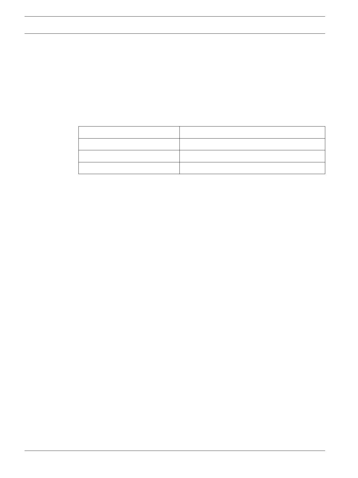
The supplied cable glands have the following specifications:
Gland type Cable clamping range
3/8-in. NPT 4.5 to 7.9 mm Ø
1/2-in. NPT 5.8 to 10 mm Ø
M20 x 1.5 3.5 to 8 mm Ø
Feed cables through the housing base
To feed cabling through the base of the housing:
1. If required, remove the camera and tray to access the holes in the base of the housing:
loosen the two screws holding the camera tray in the housing.
Slide the tray backwards and remove from the housing.
2. Remove the two dome plugs located at the bottom the housing.
3. Screw the two 3/8-in NPT fittings into the foot of the housing.
4. Feed the power cable through one of the glands.
5. Feed the ethernet/video cable through the second cable gland.
To fit the cables through the NPT fitting in the housing:
Ethernet cable: remove the RJ-45 connector and then crimp the connector back on the
cable once it is pulled through the gland. Crimp in accordance with the connector
manufacturer’s recommendations (the camera connector is Auto MDIX compliant).
Video cable: remove the BNC connector and then crimp the connector back on the cable
once it is pulled through the gland.
6. Feed any audio and alarm cables through the second gland as required.
7. Pull any excess wire out of the housing
8. Apply a seal around the cables in their glands. Use RTV or an equivalent seal (a split
rubber sleeve may also be used).
9. Tighten the cable glands. The tightening force required is approximately 1 to 1.5 turns
past the point where the gland starts to grip the wire. Failure to correctly tighten the
glands could result in water ingress.
10. Ensure that all open holes are covered with the rubber plugs provided.
11. Replace the camera and tray in the housing (if removed):
Slightly tilt the camera/lens tray assembly and slide it in under the rail that is located
under the heater on the right side of the housing.
Lower the tray so that the holes at the side fit over the two screws of the housing.
Slide the entire assembly forward approximately 5 mm (0.2 in.) from the front of the
window.
Tighten the two screws to lock the tray in place.
6
6.1
6.2
14 en | Connecting cables in housing DINION Housing Kit
2014.11 | 1.0 | F.01U.309.609 Installation Manual Bosch Security Systems
Feed cables through the housing rear
The rear holes allow cable to be fed through the supplied glands or the direct connection of
conduit fittings.
1. Remove the dome plugs located at the rear of the housing.
2. Screw the cable glands into the holes at the rear of the housing. The holes accept either
3/8‑in NPT or 1/2‑in NPT cable glands or conduit fittings. (The M20 x 1.5 cable gland can
also be used.)
3. Feed the power cable through one of the glands.
4. Feed the video/ethernet cable through a separate cable gland.
To fit the cables through the NPT fitting in the housing:
Ethernet cable: remove the RJ-45 connector and then crimp the connector back on the
cable once it is pulled through the gland. Crimp in accordance with the connector
manufacturer’s recommendations (the camera connector is Auto MDIX compliant).
Video cable: remove the BNC connector and then crimp the connector back on the cable
once it is pulled through the gland.
5. Feed any audio and alarm cables through a separate gland as required.
6. Apply a seal around the cables in their glands. Use RTV or an equivalent seal (a split
rubber sleeve may also be used).
7. Tighten the cable glands. The tightening force required is approximately 1 to 1.5 turns
past the point where the gland starts to grip the wire. Failure to correctly tighten the
glands could result in water ingress.
8. Ensure that all open holes are covered with the rubber plugs provided.
6.3
DINION Housing Kit Connecting cables in housing | en 15
Bosch Security Systems Installation Manual 2014.11 | 1.0 | F.01U.309.609
Power connections
!
Caution!
To protect the device, the branch circuit protection must be secured with a maximum fuse
rating of 16A. This must be in accordance with NEC 800 (CEC Section 60).
!
Caution!
The external ground wire must always be connected to the main ground post inside the
housing.
Incoming power safety earth connection
Connect the incoming power safety earth wire to the grounding post on the PCB bracket
assembly as follows:
1. A terminal lug (4) is provided for connecting the incoming power safety earth wire.
2. Remove the nut, the washers, and the ground wire lug from the grounding post (5).
3. Strip the incoming power safety earth wire and crimp into the lug.
4. Reattach the ground connections in the order shown:
1 Nut
2 Lock washer
3 Flat washer
4 Input power ground lug
5 Grounding post
6.4
6.4.1
16 en | Connecting cables in housing DINION Housing Kit
2014.11 | 1.0 | F.01U.309.609 Installation Manual Bosch Security Systems
Incoming power wires
The terminal block accepts wire ranging from 0.5 mm² to 2.5 mm² (20 AWG to 14 AWG). When
using larger wire sizes, splice to a smaller size wire at the terminal block end. The splice may
need to be enclosed in a junction box if it does not pass through the fittings.
1. Strip no less than 6 mm (0.25 in.) and no more than 8 mm (0.31 in.) of insulation away
from the power supply wires. Do not nick the wires.
2. Connect the incoming power wires to the AC input connectors (3) on the terminal block
as shown in the following figure:
G
x
L
N
L
AC INPUT AC OUT DC12v OUT
N
G
L
N
Callout Function
1 Power cable input to housing:
- G (green/yellow) Earth wire
- L (brown) power wire
- N (blue) power wire
2 Power input grounding post
3 AC power input terminal block connectors
4 AC power output to camera
5 12 VDC power output to camera
6 Fuse
6.4.2
DINION Housing Kit Connecting cables in housing | en 17
Bosch Security Systems Installation Manual 2014.11 | 1.0 | F.01U.309.609
Camera connections
Analog camera kit
Connect the coax cable (with BNC connector) directly to the Video connector on the back of
the camera.
If required, connect audio and alarm cables directly to back of camera.
IP camera kit
If required, connect the Cat5 / Cat6 cable to the ETH POE connector on the back of the
camera.
If required, connect audio and alarm cables directly to back of camera.
Use the composite video connector (CVBS) on the camera to connect an analog monitor for
setting up the camera or as a permanent analog output for viewing or recording:
To connect a monitor for set-up, use the optional 3 m cable (NBN-MCSMB-30M) to
connect directly to the CVBS connector of a monitor.
For a permanent analog output, use the optional 0.3 m cable (NBN-MCSMB-03M) to
connect to a high quality coax cable.
4 5 6 4 5 6
1 2 3 1 2 3
|
|
- +
MENU
CVBS
µSD
E
T
H
-
P
o
E
D
A
T
A
A
L
A
R
M
NBN-MCSMB
(optional)
6.5
18 en | Connecting cables in housing DINION Housing Kit
2014.11 | 1.0 | F.01U.309.609 Installation Manual Bosch Security Systems
Housings with rear connectors
Connection – Rear housing video connection
A BNC connector is provided on the rear of the housing. Connect the analog video cable to
this connector.
Connection – Rear housing power connection
The housings with the rear connectors already mounted are supplied with a 4-pin cable
connector for the power cable.
The 230 VAC models have a male panel connector. A female cable connector is provided.
The 24 VAC models have a female panel connector. A male cable connector is provided.
Mount the 4-pin cable connector onto the power cable:
1. Cable diameter must be between 6 mm (0.24 in) and 12 mm (0.47 in).
2. Strip no less than 6 mm (0.24 in) and no more than 8 mm (0.32 in) of insulation away
from the wire. Do not nick the wires.
3. Insert the power cord through the back shell assembly and strain relief.
4. The cable connector terminals accept wire ranging from 0.75 mm² to 2.5 mm² (18 AWG to
14 AWG).
5. Connect the power input wires to the numbered screw terminals on the mating connector
according to the table.
Connector terminal number
Function Wire color
1 AC neutral Blue
2 AC live Brown
3 No Connection (do not use) -
4 Ground Green/yellow
6. Assemble the cable connector, and plug it into the power receptacle on the housing.
Connection - rear housing feed-through fitting
Pull cables through this fitting as described in Feed cables through the housing rear, page 15.
6.6
6.6.1
6.6.2
6.6.3
DINION Housing Kit Connecting cables in housing | en 19
Bosch Security Systems Installation Manual 2014.11 | 1.0 | F.01U.309.609
Configuration and final assembly
Camera Operation
!
Warning!
Hazardous voltage
Use caution when working inside the housing. Hazardous voltage is present in the housing
when connected to the AC supply. Do not touch the power terminals when the unit is
powered.
Verify operation of the camera and lens before final assembly. If necessary, adjust the camera
orientation, focal length and focus (refer to the following configuration descriptions for analog
and IP cameras).
Other adjustments
Other minor operation adjustments are possible using the camera Menu button; these
adjustments are described in the camera Operation Guide (see Bosch website for applicable
camera).
Configuring IP camera kits
The camera normally provides an optimal picture without the need for further adjustments,
however when the kit is mounted and connected, the camera field of view and focus point
may need to be adjusted. To do this:
1. Connect a monitor to the ‘CVBS’ SMB connector on the rear of the camera.
2. Start the install wizard.
Note: For ease of connection, use the optional NBN-MCSMB-30M cable (not supplied with Kit)
to connect a monitor to the camera.
Install wizard and MENU button on camera
The MENU button on the rear panel is used for accessing the camera install wizard. The
wizard fine-tunes the focus and optimizes picture sharpness in both bright and low-level
lighting (for example, at night).
When there is a choice in the wizard, the options are selected by either a short press or a
longer press of the MENU button. Select EXIT to close the wizard.
Using Install wizard
1. Power-up the camera and wait briefly before opening the camera install wizard.
2. Briefly press Menu to start the wizard and display the following screen on the monitor:
Lens type: DC Iris State: Ready Focus indicator: 8
CONTINUE
< press short >
180° ROTATE
< press long >
Timeout: 300
The lens type is identified and shown on the screen.
The iris is opened to its maximum value.
3. To rotate the image 180°, press and hold Menu until the image flips.
4. Briefly press Menu to continue.
5. Briefly press Menu to center the focus.
7
7.1
7.2
20 en | Configuration and final assembly DINION Housing Kit
2014.11 | 1.0 | F.01U.309.609 Installation Manual Bosch Security Systems
  • Page 1 1
  • Page 2 2
  • Page 3 3
  • Page 4 4
  • Page 5 5
  • Page 6 6
  • Page 7 7
  • Page 8 8
  • Page 9 9
  • Page 10 10
  • Page 11 11
  • Page 12 12
  • Page 13 13
  • Page 14 14
  • Page 15 15
  • Page 16 16
  • Page 17 17
  • Page 18 18
  • Page 19 19
  • Page 20 20
  • Page 21 21
  • Page 22 22
  • Page 23 23
  • Page 24 24
  • Page 25 25
  • Page 26 26
  • Page 27 27
  • Page 28 28
  • Page 29 29
  • Page 30 30

Bosch NKN-71022-BA3-10N Installation guide

Category
Security cameras
Type
Installation guide
This manual is also suitable for

Ask a question and I''ll find the answer in the document

Finding information in a document is now easier with AI