2
XTP T HDMI and XTP R HDMI • Setup Guide (Continued)
68-1723-50
Rev. A
07 13
© 2013 Extron Electronics — All rights reserved. All trademarks mentioned are the property of their respective owners. www.extron.com
b. To pass bidirectional serial, infrared, or other control signals, connect a control device or a device to be
controlled to the RS-232 and IR connector (see e and k on page 1).
NOTE: RS-232 and IR data can be transmitted simultaneously.
c. Connect a host device or control LAN or WAN to the LAN RJ-45 connector for pass-through 10/100
Ethernet communication (see g and j on page 1). These are Ethernet pass-through ports with LEDs to
indicate link and activity status.
Step 4 — Connecting Outputs
a. Connect a digital video display to the HDMI connector of the
XTP R HDMI (see l on page 1).
b. Connect a balanced or unbalanced, stereo or mono audio
device to the 3.5 mm, 5-pole captive screw connector on the
receiver for 2-channel stereo analog audio (see m on page 1).
c. Connect an audio device to the female orange RCA connector for digital S/PDIF audio output (see n on page 1).
Step 5 — Connecting Control Devices, Relays, and Power
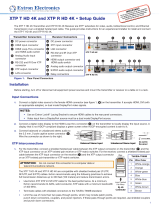
a. Connect a host device, such as a computer, to the female mini-USB B port on the front panel of the transmitter or receiver
to congure the device or update rmware (see the image to the right).
b. Connect equipment that can be controlled via momentary or latching contact, like projector screens or lifts, to these
normally open relays. Do not exceed 24 V at 1 A for each port (see o on page 1).
c. Power XTP transmitters and receivers in one of the following methods:
z Connect the provided external power supply to the 2-pole captive screw connector on both the transmitter and receiver (see a on page 1).
z Connect the provided external power supply to the 2-pole captive screw connector on a transmitter or receiver. Connect an XTP Power
Injector between the transmitter and receiver XTP connection to power the unpowered device remotely.
z Connect the transmitter or receiver to an XTP matrix switcher. Enable the remote power feature on the XTP matrix switcher.
Operation
After all transmitters, receivers, and connected devices are connected and powered on, the system is fully operational. If any issues arise, verify that
the cables are routed and connected properly.
NOTE: Use the Extron XTP System Configuration Software or SIS commands to configure the transmitter or receiver (see the
XTP T HDMI and XTP R HDMI User Guide).
HDMI Audio Switch
On either device, move and hold the HDMI audio switch up to enable embedded audio on a display connected to the associated HDMI connector or
down to disable it (for about 1 second). The switch returns to the middle position after it has been released. The associated LED lights when audio is
enabled and remains unlit when audio is disabled.
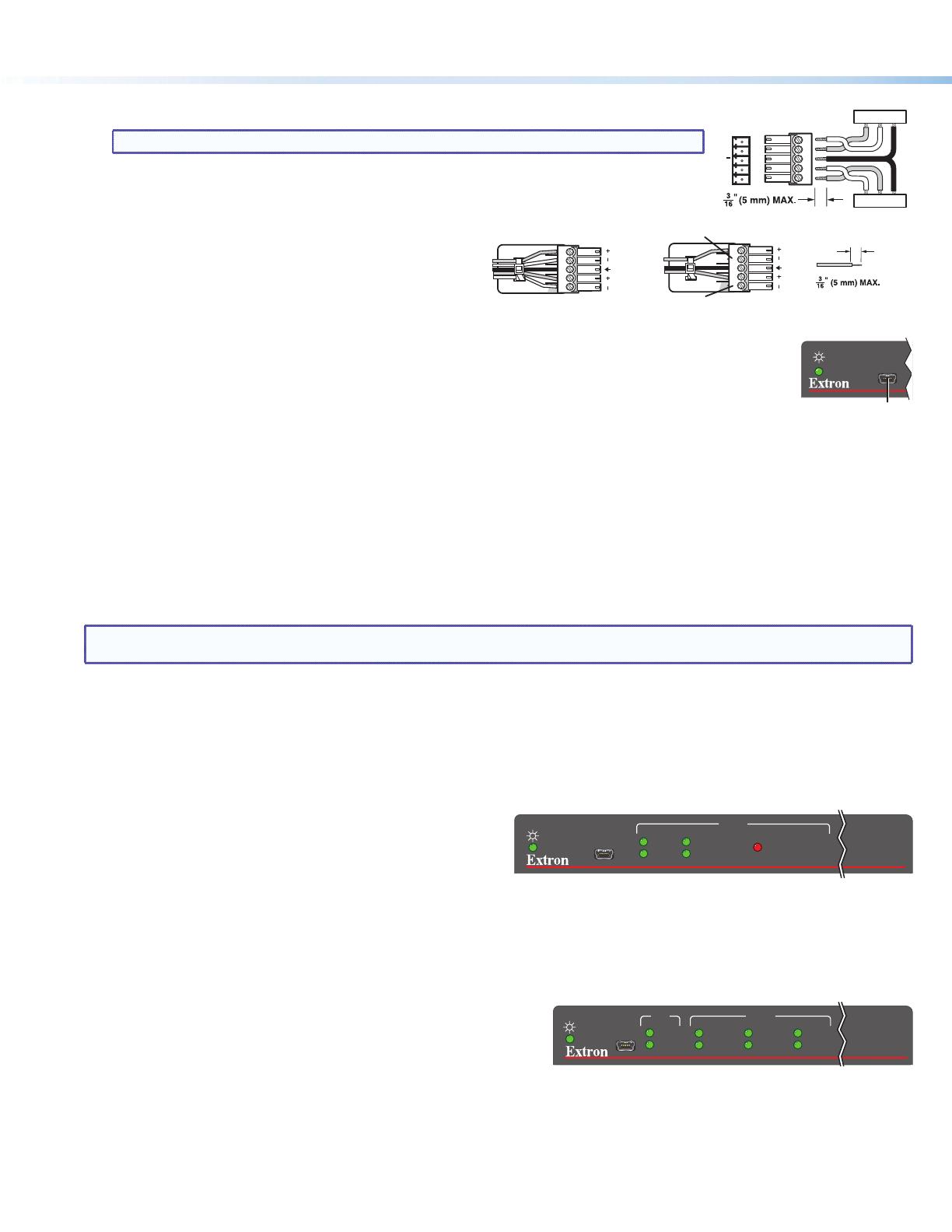
Indicators
Power LED — Lights on the front and rear panel when power is applied to the device.
Transmitter indicators
Signal LED — Lights when an active TMDS clock signal is detected from the
source.
HDCP LED — Lights when the input signal is encrypted.
HDMI Audio LED — Lights when the HDMI input audio is selected in
auto-switch mode or through SIS commands.
Analog Audio LED — Lights when the analog audio input is selected in auto-switch mode or through SIS commands.
Audio Signal Clip LED — Lights red when the analog audio input signal remains above -3 dBFS. It remains lit for 200 ms after the signal falls below
-3 dBFS.
Receiver indicators
Signal LED — Lights when an active XTP video signal is received.
HDCP LED — Lights when the input XTP signal is encrypted.
HBR LED — Lights when the embedded audio signal is high bit rate audio.
Bitstream LED — Lights when the input audio signal is Dolby Digital, DTS audio format and 2-ch Dolby.
LPCM LED — Lights when the input audio signal is LPCM-2Ch.
HDMI LED — Lights when the input audio format is multi-channel, LPCM-2Ch, or Hi-Def audio.
S/PDIF LED — Lights when the input audio format is multi-channel (except HBR) or LPCM-2Ch.
Analog LED — Lights when the input audio format is LPCM-2Ch.
Do not tin the wires!
Balanced Audio Output
Tip
Ring
Tip
Ring
ves
Unbalanced Audio Output
Tip
No Ground Here
No Ground Here
Tip
Sleeves
LR
LR
XTP T HDMI
CONFIG
INPUT
AUDIO SIGNAL CLIP
HDCP
SIGNAL
ANALOG AUDIO
HDMI AUDIO
à
CONFIG
XTP
HDCP
SIGNAL
AUDIO
HDMI
HBR
S/PDIF
BITSTREAM
ANALOG
LPCM
CONFIG
XTP
HDCP
SIGNAL
AUDIO
HDMI
HBR
S/PDIF
BITSTREAM
ANALOG
LPCM
XTP R HDMI
CONFIG
INPUT
AUDIO SIGNAL CLIP
HDCP
SIGNAL
ANALOG AUDIO
HDMI AUDIO
CONFIG
INPUT
AUDIO SIGNAL CLIP
HDCP
SIGNAL
ANALOG AUDIO
HDMI AUDIO
XTP T HDMI
Tx/Rx
Pins
RxTx
RS-232
RxTx
TxRx
RxTx
RS-232 Device
G
G
G
IR