Riverstone R1016-P User manual

Type
User manual

This manual is also suitable for

Carver
P r e m i u m C o m m e r c i a l G r e e n h o u s e
Assembly Manuals for Models:
10'(w) x 16' (d) x 8'(h)
10'(w) x 27' (d) x 8'(h)
Customer Service: (877) 373-3078 Email: [email protected]
65 Fleetwood Drive, Rockaway, NJ 07866
PARTS DESCRIPTION
3 WAY CONNECTOR
4 WAY CONNECTOR
1 5/8" X 5'1" PURLIN
1" X 2" X 10'
RECTANGLE
TUBING FOR
ENDWALL
GROUND RAIL
1" X 2" GROUND
RAIL WITH
WELDED
STANCHIONS
2" X 2"
SQUARE
TUBING USED
FOR STUDS AND
ENDWALL
FRAMING
PAGE 1
1 5/8" X 5'1" RAFTER
1 5/8" X 5'1" LEGS
PAGE 3
Ground Rails
NOTE:When setting the width for the E-Z Grow
Hobby House theOutside to outside measurement
should be 10' 4".Eaxample 10 X 16 is 10' 4" X 16'
outside to outside.
Square the structure by measuring diagonally from
corner to corner . When the diagonal measurements
are the same the structure will be square. (see photo
2.)
Example: 10'-4" wide x 16' long = 19'-9/16" diagonal
measurements.
Note: These measurements are approximate, your
measurements may be different.
Once the ground rails are squared anchor the rails
using the 12" spiked provided as shown in photo
3,4&5..
If on ground
use12" s
p
ike.
3
2
1
4
5
CONCRETE MOUNTING OPTION
front/rear ground rail
side ground rails
aluminum "z" bracket for
anchoring ground rail
tek
screws
1
4
'' concrete
drive pins
ground rail (sides or ends)
Secure aluminum "z'' bracket onto side
groundrails, evenly spaced between welded
stanchions, using #14 tek screws.
Front & Rear ground rail: place the ''z'' brackets
approximately 16'' from each end as shown in
diagram to the right.
DETAIL A. shows further attachment details.
DETAIL A.
welded
stanchions
Page 4
ASSEMBLING THE FRAME
1. Identify 3-way & 4-way connectors. 3-way connectors are for the ends and 4-way connectors are for intermediate
rafters, legs and at the peak of greenhouse.
2. Assemble frame as shown in below diagram. DO NOT assemble legs at this time, completed frame must be lifted and
placed on the legs then onto anchor posts.
3-way
connector
3-way
connector
4-way
connector
Leg (5'-1'')
purlin (5'-1'')
purlin (5'-1'')
ALL PURLIN, RAFTERS AND
LEGS ARE THE SAME LENGTH.
Rafter(5'-1")
Position 2 men approximately along one side of the
greenhouse. Holding legs in one hand, lift up one
side of greenhouse and insert legs into connectors.
Repeat on the other side.
Page 5
Page 9
Note: Slide the legs on top of the welded stanchions of the ground
rails.
Attach the endwall ground rails using the 3x 3 L-brackets. Use Tek-
screws to secure the ground rail to the frame as shown in above
picture.
OPENING MEASUREMENTS FOR FANS, SHUTTERS AND DOORS
{SUPPLIED BY ATLAS}
Fan opening for:
18” Box wall “Quietaire”
24 1/2” High X 24 1/2” Wide
30” Slant wall “Quietaire”
35 5/8” High X 34 3/4" Wide
36” Box wall “Quietaire”
40 1/2” High X 40 1/2” Wide
36” Slant wall “Quietaire”
42 1/4" High X 41” Wide
42” Slant wall “Quietaire”
48 1/2” High X 47” Wide
48” Slant wall “Quietaire”
54 1/4” High X 52 3/4” Wide
56” Slant wall “Quietaire”
65” High X 63” Wide
Shutter openings for:
24” Shutter
24 1/2” Square
30” Shutter
30 1/2” Square
39” Shutter
39 1/2” Square
45” Shutter
45 1/2” Square
48” Shutter
48 1/2” Square
60” Shutter
60 1/2” Square
Door openings for:
42” X 6’6” Swing door
Set openings 42 1/2” Wide X 78 1/2” High
4’ X 6’8’’ Swing Door
Set openings 48 1/2” Wide X 80” High
36” X 6’8” Swing door
Set openings 36” Wide X 80” High
6’ X 6’8’’ French Door
Set openings 72” Wide X 80” High
4’ X 7’ Single Sliding door
Set openings 46” Wide X 82” High
8’ X 7’ Double slide door
Set openings 96” Wide X 82” High
NOTE: Measurements are inside to inside.
All of the above listed items may not be available for your particular structure.
PAGE11
Frame out the door 30-1/2" wide x 72-1/4" high.
End wall framing attaches to the bow using a round
clamp on the bow and a square clamp on the 2"x2"
stud. See photo 2.
Attach the 2" x 2" studs to the end ground rail using
3" x 3" L-bracket as shown.
Round clamp
Square clamp
3.
2.
1.
30-1/2"
X
72-1/4"
Page 12
The Shutter opening is 24-1/2"Wide x 24-3/4" High.
Attach horizontal 2x2 using L-brackets as shown.
Note the L brackets will attach on the outside of any openings.
Example: On top of the door header, on bottom of the lower horizontal
for shutter and on top of the upper horizontal for shutter.
PAGE 13
You must field cut the ridge purlin to exact length of
the ground rails.
Attach ridge purlin with Tek-screws and two hole
clamps. The ridge purlin attaches under all bows.
Two hole clamp
Page 14
The ridge purlin is connected under all bows
using 2-hole clamps.
Prepare to attach wire lock base to the top of
the end bows, around the openings and
around the base of the greenhouse.
OPTIONAL
Cutrain will require wire lock on
the Side Purlins at the eave.
Side Purlin With Optional
Wirelock Base.
Rid
e Purlin 1-3/8"
Wire lock at base of
greenhouse
Page 15
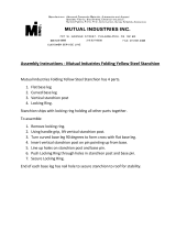
If you ordered the optional curtain system,
attach the curtain channel approximately 28"
above the ground rail. (See photo #1).
When framing is complete, wire lock base will be
attached on top of the end bows as shown in
pictures 4 & 5. The wire lock base will go from
the bottom of the ground rail over the end bow,
down to the curtain channel, then from the
curtain channel down to the bottom of the
ground rail as seen in picture 2.
Identify the curtain crank rod. Attach wire lock
base along the length of the crank rod.
Approx. 28" from
top of groundrail.
Curtain Chanel
1
2
Wire Lock Base
5
4
3
Page 16
A
ttach Wire Lock Base over the end bows using Tek
-
screws.
The wire lock base will bend over the curvatures as
shown.
Place screws approximately 12" to 16" apart.
Once the framing is complete attach wire lock base
over the top of each end bow from the bottom of the
ground rail over to the bottom of the gground rail on
the opposite side as shown. Wire lock base also
attaches all the way around the base of the
greenhouse screwing directly to the ground rails, an
d
around all door and fan openings.
IMPORTANT
NEVER APPLY POLY TOO
LOOSELY. IF POLY IS LOOSE, IT
WILL SAG BETWEEN FRAMING
MEMBERS AND “POCKET” WATER
AND /OR SNOW. THIS MAY RESULT
IN SEVERE STRUCTURAL DAMAGE
Page 17
  • Page 1 1
  • Page 2 2
  • Page 3 3
  • Page 4 4
  • Page 5 5
  • Page 6 6
  • Page 7 7
  • Page 8 8
  • Page 9 9
  • Page 10 10
  • Page 11 11
  • Page 12 12
  • Page 13 13
  • Page 14 14
  • Page 15 15
  • Page 16 16
  • Page 17 17
  • Page 18 18
  • Page 19 19
  • Page 20 20
  • Page 21 21
  • Page 22 22
  • Page 23 23
  • Page 24 24
  • Page 25 25
  • Page 26 26
  • Page 27 27
  • Page 28 28
  • Page 29 29
  • Page 30 30

Riverstone R1016-P User manual

Type
User manual
This manual is also suitable for

Ask a question and I''ll find the answer in the document

Finding information in a document is now easier with AI