Page is loading ...

Fence Distributors
YourNextFence.com
ide:
TM
TM

each line by dividing the length of
each line in inches by 97. Round any
remainder up.
Plan Your Fence
Fence Distributors
2
TM

3
Stakes
String Line
Marking Paint
Hammer
Tape Measure
Shovel
Post Hole Digger
Digging Bar
Circular Saw
Drill
Pencil
Wheelbarrow
4’ Level
Miter Saw
Speed Square
Finish Nn
Tools Needed
you dig.
Check local HOA and zoning laws
which may regulate the height and
placement of your fence.
Apply for local permits as directed
by local code
eyes and ears.
Before you begin
Calculate Materials
Fence Distributors
3
TM
https://www.yournextfence.com/horizons/installation

Exploded View
A. 1 Trex® Post Cap
B. 1 Trex® Post
C. 2 Horizons™ Horizontal Top Rail Brackets
D.
E.
F.
. 15 Trex® Fence Pickets (91 1/2”)
Horizons™ Horizontal Rails
A
B
C
C
D
D
E
E
F
F
G
Fence Distributors
4
Horizons™ Vertical Front Rails
Horizons™ Vertical Back Rails
Horizons™ COMPOSITE FENCING SYSTEM is a trademark of FDS Distributors. Patent Pending.
Trex® is a federally registered trademark of Trex Company, Inc., Winchester, Virginia.
TM
H. 50 #10 x 3/4” Panhead Screws

5
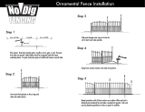
Step 1: Understand Install Method
1. Step Method: This method gradually “steps”
up the slope and the rails remain level. This
may leave gaps under the fence. The downhill
post will need to be set taller. Longer posts
may be required. When laying out the fence
post spaeasure on a level line from one
post to another.
5
Fence Distributors
TM

pins so that stakes will not be disturbed when digging holes and approx.
4-5 inches inside of property pins to insure not to encroach on neighbors
property (See Fig.1).
2.
string every 97” on center. Ideal spacing between posts is 92”. If
2” in
from the string to mark the center of the hole (see Fig. 1).
Step 2: Stake and String
Fig. 1
Step 3: Dig Holes
1. Dig the holes for the posts making sure not to disturb the stakes for the string.
be approximately 12” diameter and 30”
should be dug so they allow equal amounts of concrete on all sides of posts (see g. 2).
Fence Distributors
6
TM

7
Fence Distributors
7
TM
If posts will be set on sloping or uneven grou or will be stepping skip to step 4B.
1. two screws (3 3/4” below the
top of each post). End posts will only have one bracket that faces
two sides (see Fig.3)
.
2. Set the rst post in the hole. Plumb and level the post to the string
line (ensure that the post is 76 3/4” high*) and ll the hole around
the post with concrete mix.
3. Place post into the next hole. Place a horizontal rail onto the
brackets. Use a level on
the rail and raise or lower
the previous post. This rail
will also ensure that your
posts are spaced correctly
(see Fig.3). Plumb and level
the post to the string line and
l the hole around the post
with concrete mix.
4.
all posts are set.
3 3/4”
Fig. 3
A
30” Min. Typ.
Consult local
conditions and
codes for post
depth
Fig. 2
76 3/4”

Fence Distributors
8
TM
1. elow the top of the post to one side
of each post using two screws (see Fig.4).
2. Set the uphill post st. This post should be set at 76 3/4” tall with the bracket
facing to the next post down hill. Plumb and level the post to the string line.
Fill the hole around the post with concrete mix (see Fig. 4).
3. Place the next downhill post in its hole with the bracket facing uphill towards the
last post that you set. Place a horizontal rail onto the brackets of the two posts
and place a level on the rail. Adjust the post height of the downhill post
Plum
b and level the post and ll the hole around the post with concrete mix.
30” Min. Typ.
Consult local
conditions and
codes for post
depth
12”
76 3/4”
3 3/4”
Fig. 4
Fig. 5
4B
the rail is level (see Fig. 5). This will also ensure that posts are spaced correctly.

9
Fence Distributors
9
TM
4.
pos and subtract this from the height of the rail on the rst post. Add this
measurement to 3 3/4” and this will be the placement of the downhill bracket
(see Fig. 6).
8 5/8”
1. etween
(see Fig. 7). Touch up the cut end using a zinc rich primer and a matching top
coat to help prevent rust.
Fig 6
5.
5: Cut Horizontal Rails
Be sure to cut only one end of the rails
79 3/8”
-74 1/2”
5 1/8”
+3 3/4”
8 5/8”
Fig 7
to cut the horizontal rails for length. Measure between the posts and cut

1.
Fig. 10
2. Place a horizontal rail over the brackets with the screw holes facing you. If the
drop the other end over the other bracket (see Fig. 8).
Fig 8
Step 6: Attach Vertical Back Rails
Vertical
Back
Rail
Top Rail
screw holes
bracket
Fig. 9
Fence Distributors
10
TM

11
Step 7A: Notch and Hang Top Picket
Fig. 11
Fig. 12
11
Fence Distributors
TM
Horizontal Rail
Picket Vertical Back Rail
2. Remove the horizontal rail and slide the picket onto the rail with the notches
1.

Step 7B: Hang The Pickets
1. Hang the remaining 14 pickets from the top picket by interlocking them to each
other (see Fig. 13
2. Before installing the last picke slide the remaining horizontal rail onto the
Fig. 14
Fig. 13
12
Fence Distributors
TM

12
1.
Fig. 16
Step 8:
2. Screw the horizontal rails to the pickets (see Fig. 16).
Fence Distributors
13
Fig. 15
TM

2. Place post caps onto the post and
secure using adhesive or nish
nails. (see g. 18).
Fig. 16
Fig. 18
Step 9: Secure Vertical Rails to Horizontal Rails
Fig. 17
Fence Distributors
14
TM
https://www.yournextfence.com/horizons/installation
1.
in each corner on both front and back sides (see Fig. 17). Pre-drill each hole
using a 5/32” drill bit.

Fence Distributors
15
Install Single ate
A. Trex® Fence Post
B. Horizons™ate Panel
C.
D. ate Hinge (2)
E. Horizons™ ate Latch
F. Horizons™ ate Striker
ate Handle (2)
Horizons™ COMPOSITE FENCING SYSTEM is a trademark of FDS Distributors. Patent Pending.
Trex® is a federally registered trademark of Trex Company, Inc., Winchester, Virginia.
TM

Fence Distributors
16
tep 1: Set the ate Posts
A.
faces away from the gate opening.
B. Set posts** into post holes. The holes should be 30” deep
by 12” wide***. Plumb and level posts so they are parallel
with each other and ll the hole with concrete mix.
C. The opening (measuring from the inside face of one post
to inside face of the other post) for a standard size Trex
Horizonste panel should be 46 1/4”. (****The opening
for a standard Large Size Trex ate panel is 65 3/4” wide)
Custom heights and widths are possible.
**Note: Due to concrete cure
-3
days before gate is installed.
*Note: If the Hinge Post is not
connected to a fence panel or
if a large gate panel is used it
may be necessary to use a
***Note:
and codes for actual depth.
**
TM

Fence Distributors
17
tep 2: Install tate Panel
A. Using a 3/8” 6”
1/2” self-drilling
screws. Pre-drilling with a 3/16”
B. Place the gate panels in the opening. Adjust the gates so the top rail lines
up with the top rail of the fence.
C. Using the supplied 1 1/2” self-
the outside corner of each hinge to the gate post con-
-drilling with a 3/16” drill
D.
the hinge bracket to the hinge post.
A
B
C
D
TM

Fence Distributors
18
A.
11/16” wrench.
B.
C.
Note: Due to weather and temperature changes periodic hinge adjustment may be necessary to
A. 36” from the ground (or to de-
sired height) using the supplied 1 1/2” self-drilling screws. The latch should be ori-
ented so the catch is on the gate-swing side of the post. The catch will face up or
B. Using the supplied 1 1/2” self-
to the gate pane lining the strik-
er rod up with the catch on the
post latch.
C.
gate panel upright using the sup-
plied 1” self-drilling screws. Han-
3/4” in
from the edge of the gate panel.
The handle height must be staggered
A
B
C
TM

Fence Distributors
19
Install Doubleate
A. Trex® Fence Post (2)
B. Horizons™ate Panel (2)
C.
D. ate Hinge (4)
E. Horizons™ ate Latch
F. Horizons™ ate Striker
ate Handle (2)
(2)
H. FDS Drop Rod
Horizons™ COMPOSITE FENCING SYSTEM is a trademark of FDS Distributors. Patent Pending.
Trex® is a federally registered trademark of Trex Company, Inc., Winchester, Virginia.
TM

Fence Distributors
20
tep 1: Set the ate Posts
A.
B. Set posts into post holes**. The holes should be 30”deep by 12”
wide***. Plumb and level posts so they are parallel with each
other and ll hole with concrete mix .
C. The opening (measuring from the inside face of one post to in-
side face of the other post) for 2 standard size Trex Horizons
te panels should be 91 1/2” wide. (****The opening for a dou-
ble gate using Large Trete panels is 130 1/2” wide) Custom
heights and widths are possible.
**Note: Due to concrete cure
-3
days before gate is installed.
*Note: If the Hinge Post is not
connected to a fence panel or if
a large gate panel is used it may
be necessary to use a Heavy
***Note:
and codes for actual depth.
**
TM
/