User Manual
NorSap 1100
NorSap models
5025 NorSap 1100 390-490 no foot rest
5050 NorSap 1100 510-690
5075 NorSap 1100 630-920
5080 NorSap 1100 410-510 w/5 leg no foot rest
5083 NorSap 1100 530-710 w/5 leg
5085 NorSap 1100 650-940 w/5 leg Ø600
5090 NorSap 1100 chair top no column
norsap.com
March, 2015
NorSap 1100

E-mail
sale@norsap.com
Web
norsap.com
Telephone
+47 38 18 52 00
Mjåvannsvegen 45/47
4628 Kristiansand, Norway
TABLE OF CONTENTS
Introduction .......................................... 2
Function ................................................. 2
Mounting ............................................... 3
Care and maintenance ...................... 3
Replacing / replacement .................. 4
Eqiupment and spare part............... 5
Adjustments ........................................ 6
Safety ...................................................... 7
INTRODUCTION
Congratulations on your purchase of a NorSap chair! NorSap is the recognized
leader in the design and production of helmsman and operator seats for the
maritime market.
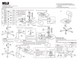
Chair swivel/turn release handle
Backrest gas-strut release handle
Height adjustment release handle
Hight adjustable footrest handle
Adjustable backrest/seat rest
release handle
FUNCTIONS OF THE NORSAP 1100 CHAIR
This manual will help
you make the most out
of your NorSap chair.
If you have any questions regarding
your NorSap chair, please contact our
head oce for further assistance.
ADDITIONAL
•
Chair swivels 360°
•
Footrest and armrests folds up
•
Fully reclining backrest
•
Horizontal glide rails
1
5
2
3
4
5
1
2
3
4

NorSap 1100
/
3
MOUNTING ON A DECK RAIL
First, make sure to have mounted the deck rail according to its user manual.
The bolts for mounting the chair to the deck rail is already in place in the carrier wagon.
If you have a standard deck rail with release from seated position, the mounting
of the release lever is shown in the deck rails user manual.
If you have a basic deck rail, the wiring and mounting of the release lever is
shown in the deck rails user manual.
Braket for release handel - Item No: P13470.
MOUNTING HOLES MEASUREMENTS
A strong and level foundation is required
to secure the installation of the base.
Use six (6) M6 bolts to mount the pedestal
96 mm
CARE AND MAINTENANCE OF LEATHER
As a natural product, leather is very durable and hardwearing, but all leather products
require cleaning and protecting. By following these instructions, you will ensure a long
and lasting leather quality. Never place leather furniture closer than 20-30 cm to a radia-
tor or in direct sunlight.
LEATHER CLEANING
Cleaning removes everyday dirt and
stains from your leather. Without proper
cleaning the leather will over a period of
time leave grease spots or discoloration’s.
To avoid this, clean with Soft Cleaner on a
regular basis, we advise once a month.
LEATHER PROTECTION
Protect your leather to guarantee that
the original quality of the leather will
be maintained. Use Leather Protection
Cream, we advise 2-4 times a year. This
will protect against spots and preserve
the leathers softness.
96 mm
206 mm
CARE AND MAINTENANCE OF FABRIC
Regular light vacuuming. Occasional cleaning should be done with a reputable brand of
upholstery shampoo following the manufacturer’s instructions
264 mm

4
/
NorSap 1100
If your upholstery is damaged or worn, it is recommended to replace the whole cushion.
REPLACING SEAT AND BACKREST CUSHIONS
SEAT REST CUSHION
The seat cushion is connected to the base with four (4)
double ended pine tree clip in nylon.
REMOVE: Grip the seat at the front and back edge.
Lift and pull to remove.
REPLACE: Align the seat cushion over the four pine tree
clips and push down until you hear it clicks.
Note: extra pine tree clip is delivered with each chair - Item no: LAAS-026
BACKREST CUSHION
To replace the backrest cushion, remove the seat rest cushion rst.
wire føringer-beskj
WEIGHT: 11.27
A3
SHEET 1 OF 1
SCALE:1:5
DWG NO.
TITLE:
REVISION
DO NOT SCALE DRAWING
MATERIAL:
DATE
SIGNATURE
NAME
DEBUR AND
BREAK SHARP
EDGES
FINISH:
UNLESS OTHERWISE SPECIFIED:
DIMENSIONS ARE IN MILLIMETERS
SURFACE FINISH:
TOLERANCES:
LINEAR:
ANGULAR:
Q.A
MFG
APPV'D
CHK'D
DRAWN
BOLTS
Loosen the bolts on the back hinge mount-
ing plate on both sides. To easily access the
bolts, recline the backrest.
BOLTS
Remove the bolts on the back hinge
mounting plate on both sides. To access
the bolts, pull aside the cushion in the
bottom corner from the outside.
GAS STRUT
Remove the Seeger ring to remove the
wire/gas strut. Remove the wire/gas strut
by pressing the bolt.
REPLACING ARMRESTS
To replace the armrest, unscrew the seven (7) bolts
holding the armrest in place. Replace the armrest with
the new one and re-mount.
REMOUNT
First mount the gas-strut to backrest before remounting the backrest to the seat.
Slide the backrest back on place and remount bolts at the back hinge mounting plate
1
3
X
7
X
4
2
1
3
2

NorSap 1100
/
5
Item Name Item No Rev
NS1100 Seat rest cushion PUTE-114 A1
NS1100 Back rest cushion PUTE-115 A1
Item Name Item No Rev
NS1100 Armrest Right PUTE-120H A1
NS1100 Armrest Left PUTE-120V A1
Item Name Item No
Foot rest padding STL-006
Wheel set (5) for Oce chairs HJUL-007
Item Name Item No Pos
Complete footrest DEL-073BP
Adjustable hand wheel 8X63 RATT-018 1
Shell Ø13 L=25mm SAP-0576-25 2
REPLACEMENT / SPARE PARTS ALL MODELS
To nd out what model your chair is, ip up seat and check the label underneath.
Item Name Item No Rev
NS1100 Column, low with base (for chair 5025) A1041 A1
NS1100 Column, medium with base (for chair 5050) A1043 A1
NS1100 Column, high with base (for chair 5075) A0934 A1
Item Name Item No Rev
NS1100 Column, low with 5 legs (for chair 5080) A0901 A1
NS1100 Column, medium with 5 legs (for chair 5083) A1090 A1
NS1100 Column, high with 5 legs (for chair 5085) A1086 A1
FOOTREST
SEAT PILLOWS
ARMREST
5STAR BASE
COLUMNS
2
1

6
/
NorSap 1100
WIRE ADJUSTMENTS
Item Name Item No
WIRE L= 570MM WIRE-023
TIGHTEN WIRE
Tighten the screws.
Be careful not to
tighten too much.
Function test before
reassembly.
REPLACING WIRE
To replace the wire,
unscrew the two (2)
bolts on the handle
spring. Then you
have access to the
wire, replace it with
the new one and
re-mount.
Be careful not to tighten the bolts on the
handle spring too much.
Function test before reassembly.
MAINTENANCE OF MOVING PARTS
The glide parts of the chair can be lubricated with a silicone-based lubricant.
If the chair is on a deck rail, it is important that the deck rails NOT lubricate.
CORRECT PLACEMENT
The illustrations shows the correct
placement of the wires.

NorSap 1100
/
7
GAS STRUT ADJUSTMENT
If the cable for the backrest gas-strut is dismounted, it is important to reassure that it is
re-assembled correctly.
The illustration shows the
correct placement of the
gas-strut end into the cable
release head.
The release-pin of the gas-strut
should be mounted as close
as possible to the release, but
not under pressure. Make sure
it almost touches the piston (a
clearance of <1mm).
Function test before
reassembly.
Item Name Item No
K0B1G73 063 236 1100N GAS-069
SAFETY
Be sure to keep hands and ngers out of moving parts areas when operating the chair.
SWING REDUCTION
To avoid breakage of cables and wires within the column, a
360° swivel restrictions need to be applied. First you have to
remove the seat cushion as described, then you gain access
to the swing locking plate.
Place a B415-M6x8 bolt with two (2) B481-M6 washers.
Use one of the tree remaining holes.
Item Name Item No
UNBRAKOSKR SYL A4 6X8 DI B415-M6x8
SKIVE M/LITEN DIAM.M6 A4 D125 B481-M6

norsap.com
/