
ACCULINK
3162 DSU/CSU
USER’S GUIDE
Document No. 3162-A2-GB20-40
August 2000

A
3162-A2-GB20-40
August 2000
Copyright E 2000 Paradyne Corporation.
All rights reserved.
Printed in U.S.A.
Notice
This publication is protected by federal copyright law. No part of this publication may be copied or distributed,
transmitted, transcribed, stored in a retrieval system, or translated into any human or computer language in any form
or by any means, electronic, mechanical, magnetic, manual or otherwise, or disclosed to third parties without the
express written permission of Paradyne Corporation, 8545 126th Ave. N., Largo, FL 33773.
Paradyne Corporation makes no representation or warranties with respect to the contents hereof and specifically
disclaims any implied warranties of merchantability or fitness for a particular purpose. Further, Paradyne Corporation
reserves the right to revise this publication and to make changes from time to time in the contents hereof without
obligation of Paradyne Corporation to notify any person of such revision or changes.
Changes and enhancements to the product and to the information herein will be documented and issued as a new
release to this manual.
Warranty, Sales, Service, and Training Information
Contact your local sales representative, service representative, or distributor directly for any help needed. For
additional information concerning warranty, sales, service, repair, installation, documentation, training, distributor
locations, or Paradyne worldwide office locations, use one of the following methods:
H Internet: Visit the Paradyne World Wide Web site at www.paradyne.com. (Be sure to register your warranty
at www.paradyne.com/warranty.)
H Telephone: Call our automated system to receive current information by fax or to speak with a company
representative.
— Within the U.S.A., call 1-800-870-2221
— Outside the U.S.A., call 1-727-530-2340
Trademarks
ACCULINK, COMSPHERE, FrameSaver, Hotwire, and NextEDGE are registered trademarks of Paradyne
Corporation. MVL, OpenLane, Performance Wizard, and TruePut are trademarks of Paradyne Corporation. All other
products and services mentioned herein are the trademarks, service marks, registered trademarks, or registered
service marks of their respective owners.
Document Feedback
We welcome your comments and suggestions about this document. Please mail them to Technical Publications,
Paradyne Corporation, 8545 126th Ave. N., Largo, FL 33773, or send e-mail to [email protected]. Include
the number and title of this document in your correspondence. Please include your name and phone number if you
are willing to provide additional clarification.

Important Information
B
3162-A2-GB20-40 August 2000
!
Important Safety Instructions
1. Read and follow all warning notices and instructions marked on the product or included in the manual.
2. This product is intended to be used with a 3-wire grounding type plug – a plug which has a grounding pin. This is
a safety feature. Equipment grounding is vital to ensure safe operation. Do not defeat the purpose of the
grounding type plug by modifying the plug or using an adapter.
Prior to installation, use an outlet tester or a voltmeter to check the ac receptacle for the presence of earth
ground. If the receptacle is not properly grounded, the installation must not continue until a qualified electrician
has corrected the problem.
If a 3-wire grounding type power source is not available, consult a qualified electrician to determine another
method of grounding the equipment.
3. Slots and openings in the cabinet are provided for ventilation. To ensure reliable operation of the product and to
protect it from overheating, these slots and openings must not be blocked or covered.
4. Do not allow anything to rest on the power cord and do not locate the product where persons will walk on the
power cord.
5. Do not attempt to service this product yourself, as opening or removing covers may expose you to dangerous
high voltage points or other risks. Refer all servicing to qualified service personnel.
6. General purpose cables are provided with this product. Special cables, which may be required by the regulatory
inspection authority for the installation site, are the responsibility of the customer.
7. When installed in the final configuration, the product must comply with the applicable Safety Standards and
regulatory requirements of the country in which it is installed. If necessary, consult with the appropriate regulatory
agencies and inspection authorities to ensure compliance.
8. A rare phenomenon can create a voltage potential between the earth grounds of two or more buildings. If
products installed in separate buildings are interconnected, the voltage potential may cause a hazardous
condition. Consult a qualified electrical consultant to determine whether or not this phenomenon exists and, if
necessary, implement corrective action prior to interconnecting the products.
9. Input power to the ac voltage configuration of this product must be provided by a UL-listed or CSA-certified power
source with a Class 2 or Limited Power Source (LPS) output.
10. This product contains a coin cell lithium battery that is only to be replaced at the factory. Caution: There is a
danger of explosion if the battery is incorrectly replaced. Replace only with the same type. Dispose of used
batteries according to the battery manufacturer’s instructions. Attention: Il y a danger d’explosion s’il y a
remplacement incorrect de la batterie. Remplacer uniquement avec une batterie du même type. Mettre au rebut
les batteries usagées conformément aux instructions du fabricant.
11. In addition, if the equipment is to be used with telecommunications circuits, take the following precautions:
— Never install telephone wiring during a lightning storm.
— Never install telephone jacks in wet locations unless the jack is specifically designed for wet locations.
— Never touch uninsulated telephone wires or terminals unless the telephone line has been disconnected at the
network interface.
— Use caution when installing or modifying telephone lines.
— Avoid using a telephone (other than a cordless type) during an electrical storm. There may be a remote risk of
electric shock from lightning.
— Do not use the telephone to report a gas leak in the vicinity of the leak.

Important Information
C
3162-A2-GB20-40
August 2000
!
UNITED STATES – EMI NOTICE:
This equipment has been tested and found to comply with the limits for a Class A digital device,
pursuant to Part 15 of the FCC rules. These limits are designed to provide reasonable protection against
harmful interference when the equipment is operated in a commercial environment. This equipment
generates, uses, and can radiate radio frequency energy and, if not installed and used in accordance
with the instruction manual, may cause harmful interference to radio communications. Operation of this
equipment in a residential area is likely to cause harmful interference in which case the user will be
required to correct the interference at his own expense.
The authority to operate this equipment is conditioned by the requirements that no modifications will be
made to the equipment unless the changes or modifications are expressly approved by Paradyne
Corporation.
!
CANADA – EMI NOTICE:
This Class A digital apparatus meets all requirements of the Canadian interference-causing equipment
regulations.
Cet appareil numérique de la classe A respecte toutes les exigences du règlement sur le matérial
brouilleur du Canada.

Important Information
D
3162-A2-GB20-40 August 2000
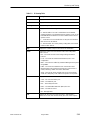
Government Requirements and Equipment Return
Certain governments require that instructions pertaining to CSU connection to the telephone network be included in
the installation and operation manual. Specific instructions are listed in the following sections.
United States
NOTICE TO USERS OF THE UNITED STATES TELEPHONE NETWORK
1. This equipment complies with Part 68 of the FCC rules. On the bottom of the DSU/CSU is a label that contains,
among other information, the FCC registration number. If requested, this information must be provided to the
telephone company.
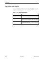
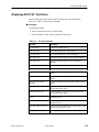
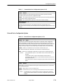
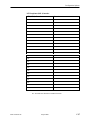
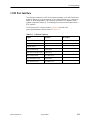
2. The T1 network connection should be made using a Universal Service Order Code (USOC) type RJ48C jack. The
Service Order Code 6.0F should be specified to the telephone company when ordering the T1 line. In addition,
the proper Facility Interface Code must be specified to the telephone company. The DSU/CSU can be configured
to support any of the following framing format and line signaling techniques. The DSU/CSU configuration must
correspond to the T1 line’s parameters.
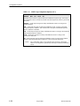
DSU/CSU Facility Interface Codes
Code
Description
04DU9-BN 1.544 Mbps superframe format (SF) without line power
04DU9-DN 1.544 Mbps SF and B8ZS without line power
04DU9-1KN 1.544 Mbps ANSI ESF without line power
04DU-1SN 1.544 Mbps ANSI ESF and B8ZS without line power
3. An FCC compliant telephone cord and modular plug is provided with this equipment. This equipment is designed
to be connected to the telephone network or premises wiring using a compatible modular jack which is Part 68
compliant. See the installation instructions for details.
4. If the DSU/CSU causes harm to the telephone network, the telephone company will notify you in advance that
temporary discontinuance of service may be required. But if advance notice is not practical, the telephone
company will notify the customer as soon as possible. Also, you will be advised of your right to file a complaint
with the FCC if you believe it is necessary.
5. The telephone company may make changes in its facilities, equipment, operations, or procedures that could affect
the operation of the equipment. If this happens, the telephone company will provide advance notice in order for
you to make the necessary modifications in order to maintain uninterrupted service.
6. If you experience trouble with this equipment, please contact your sales or service representative (as appropriate)
for repair or warranty information. If the product needs to be returned to the company service center for repair,
contact them directly for return instructions using one of the following methods:
H Internet: Visit the Paradyne World Wide Web site at http://www.paradyne.com
H Telephone: Call our automated call system to receive current information or to speak with a company
representative.
— Within the U.S.A., call 1-800-870-2221
— Outside the U.S.A., call 727-530-2340
If the trouble is causing harm to the telephone network, the telephone company may request that you remove the
equipment from the network until the problem is resolved.

Important Information
E
3162-A2-GB20-40
August 2000
7. If your DSU/CSU is in need of repair, refer to the Warranty, Sales and Service Information section on page A.
8. No repairs may be made by the customer.
Canada
NOTICE TO USERS OF THE CANADIAN TELEPHONE NETWORK
The Industry Canada label identifies certified equipment. This certification means that the equipment meets
telecommunications network protective, operational, and safety requirements as prescribed in the appropriate
Terminal Equipment Technical Requirements document(s). The Department does not guarantee the equipment will
operate to the user’s satisfaction.
Before installing this equipment, users should ensure that it is permissible to be connected to the facilities of the local
telecommunications company. The equipment must also be installed using an acceptable method of connection. The
customer should be aware that compliance with the above conditions may not prevent degradation of service in some
situations.
Repairs to certified equipment should be coordinated by a representative designated by the supplier. Any repairs or
alterations made by the user to this equipment, or equipment malfunctions, may give the telecommunications
company cause to request the user to disconnect the equipment.
Users should ensure for their own protection that the electrical ground connections of the power utility, telephone
lines, and internal metallic water pipe system, if present, are connected together. This precaution may be particularly
important in rural areas.
CAUTION:
Users should not attempt to make such connections themselves, but should contact the appropriate
electric inspection authority, or electrician, as appropriate.
The Ringer Equivalence Number (REN) assigned to each terminal device provides an indication of the maximum
number of terminals allowed to be connected to a telephone interface. The termination on an interface may consist of
any combination of devices subject only to the requirement that the sum of the Ringer Equivalence Numbers of all the
devices does not exceed 5.
If your equipment is in need of repair, refer to the procedure on page A of this document.

i
3162-A2-GB20-40
August 2000
Contents
About This Guide
H Document Purpose and Intended Audience vii. . . . . . . . . . . . . . . . . . . . . . . . .
H Document Summary vii. . . . . . . . . . . . . . . . . . . . . . . . . . . . . . . . . . . . . . . . . . . . .
H Product-Related Documents viii. . . . . . . . . . . . . . . . . . . . . . . . . . . . . . . . . . . . . .
H Reference Documents ix. . . . . . . . . . . . . . . . . . . . . . . . . . . . . . . . . . . . . . . . . . .
1 Introduction
H Overview 1-1. . . . . . . . . . . . . . . . . . . . . . . . . . . . . . . . . . . . . . . . . . . . . . . . . . . . . .
H Features 1-1. . . . . . . . . . . . . . . . . . . . . . . . . . . . . . . . . . . . . . . . . . . . . . . . . . . . . . .
DTE Drop/Insert (DSX-1) Interface 1-2. . . . . . . . . . . . . . . . . . . . . . . . . . . . .
Asynchronous Terminal Interface Support 1-2. . . . . . . . . . . . . . . . . . . . . .
Alarm Message Capability 1-2. . . . . . . . . . . . . . . . . . . . . . . . . . . . . . . . . . . .
Telnet Access 1-2. . . . . . . . . . . . . . . . . . . . . . . . . . . . . . . . . . . . . . . . . . . . . . .
SNMP Management Support 1-2. . . . . . . . . . . . . . . . . . . . . . . . . . . . . . . . . .
H Physical Description 1-3. . . . . . . . . . . . . . . . . . . . . . . . . . . . . . . . . . . . . . . . . . . . .
2 Installation
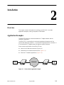
H Overview 2-1. . . . . . . . . . . . . . . . . . . . . . . . . . . . . . . . . . . . . . . . . . . . . . . . . . . . . .
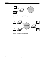
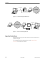
H Application Examples 2-1. . . . . . . . . . . . . . . . . . . . . . . . . . . . . . . . . . . . . . . . . . . .
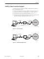
H SNMP or Telnet Connection Examples 2-3. . . . . . . . . . . . . . . . . . . . . . . . . . . . .
H Important Instructions 2-4. . . . . . . . . . . . . . . . . . . . . . . . . . . . . . . . . . . . . . . . . . . .
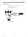
H Cabling Example 2-5. . . . . . . . . . . . . . . . . . . . . . . . . . . . . . . . . . . . . . . . . . . . . . . .
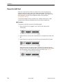
H Power-On Self-Test 2-6. . . . . . . . . . . . . . . . . . . . . . . . . . . . . . . . . . . . . . . . . . . . .

Contents
ii
3162-A2-GB20-40
August 2000
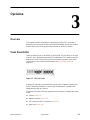
3 Operation
H Overview 3-1. . . . . . . . . . . . . . . . . . . . . . . . . . . . . . . . . . . . . . . . . . . . . . . . . . . . . .
H Front Panel LEDs 3-1. . . . . . . . . . . . . . . . . . . . . . . . . . . . . . . . . . . . . . . . . . . . . . .
H Initiating an Asynchronous Terminal Session 3-5. . . . . . . . . . . . . . . . . . . . . . . .
H Ending an Asynchronous Terminal Session 3-5. . . . . . . . . . . . . . . . . . . . . . . . .
H Recovering Asynchronous Terminal Operation 3-6. . . . . . . . . . . . . . . . . . . . . .
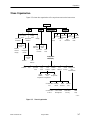
H Menu Organization 3-7. . . . . . . . . . . . . . . . . . . . . . . . . . . . . . . . . . . . . . . . . . . . . .
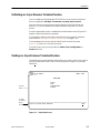
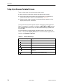
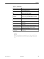
H Using Asynchronous Terminal Screens 3-8. . . . . . . . . . . . . . . . . . . . . . . . . . . .
H Entering a Password to Gain Access 3-10. . . . . . . . . . . . . . . . . . . . . . . . . . . . . .
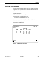
H Displaying LED Conditions 3-11. . . . . . . . . . . . . . . . . . . . . . . . . . . . . . . . . . . . . . .
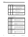
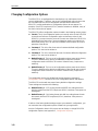
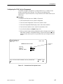
H Changing Configuration Options 3-12. . . . . . . . . . . . . . . . . . . . . . . . . . . . . . . . . .
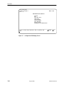
Displaying or Editing Configuration Options 3-13. . . . . . . . . . . . . . . . . . . . .
Saving Edit Changes 3-15. . . . . . . . . . . . . . . . . . . . . . . . . . . . . . . . . . . . . . . . .
4 Configuration
H Overview 4-1. . . . . . . . . . . . . . . . . . . . . . . . . . . . . . . . . . . . . . . . . . . . . . . . . . . . . .
H Setting Customer Identification 4-2. . . . . . . . . . . . . . . . . . . . . . . . . . . . . . . . . . . .
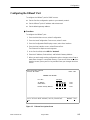
H Configuring the 10BaseT Port 4-3. . . . . . . . . . . . . . . . . . . . . . . . . . . . . . . . . . . .
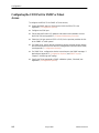
H Configuring the COM Port for SNMP or Telnet Access 4-4. . . . . . . . . . . . . . .
Configuring the COM Port for Management 4-5. . . . . . . . . . . . . . . . . . . . .
Setting the IP Address 4-6. . . . . . . . . . . . . . . . . . . . . . . . . . . . . . . . . . . . . . .
Selecting the Link Layer Protocol 4-7. . . . . . . . . . . . . . . . . . . . . . . . . . . . . .
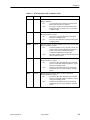
H Configuring DS0 Channels 4-8. . . . . . . . . . . . . . . . . . . . . . . . . . . . . . . . . . . . . . .
Displaying DS0 Channel Assignments 4-12. . . . . . . . . . . . . . . . . . . . . . . . .
Allocating DS0 Channels from the DTE Drop/Insert Interface to the
Network Interface 4-14. . . . . . . . . . . . . . . . . . . . . . . . . . . . . . . . . . . . . . . . . . . .
Configuring DS0 Channels for Robbed Bit Signaling 4-15. . . . . . . . . . . . .
Allocating Data Ports Using the Block or ACAMI Assignment
Method 4-16. . . . . . . . . . . . . . . . . . . . . . . . . . . . . . . . . . . . . . . . . . . . . . . . . . . . .
Allocating Data Ports Using the Individual Channel Assignment
Method 4-17. . . . . . . . . . . . . . . . . . . . . . . . . . . . . . . . . . . . . . . . . . . . . . . . . . . . .
Clearing DS0 Channel Allocation 4-17. . . . . . . . . . . . . . . . . . . . . . . . . . . . . .
H Establishing Access Security on the COM Port 4-18. . . . . . . . . . . . . . . . . . . . . .
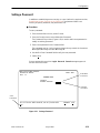
H Setting a Password 4-19. . . . . . . . . . . . . . . . . . . . . . . . . . . . . . . . . . . . . . . . . . . . . .
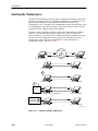
H Selecting the Timing Source 4-20. . . . . . . . . . . . . . . . . . . . . . . . . . . . . . . . . . . . . .
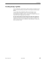
H Providing Backup Capability 4-21. . . . . . . . . . . . . . . . . . . . . . . . . . . . . . . . . . . . . .

Contents
iii
3162-A2-GB20-40
August 2000
5 Monitoring and Testing
H Overview 5-1. . . . . . . . . . . . . . . . . . . . . . . . . . . . . . . . . . . . . . . . . . . . . . . . . . . . . .
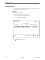
H Self-Test Results 5-1. . . . . . . . . . . . . . . . . . . . . . . . . . . . . . . . . . . . . . . . . . . . . . . .
H Device Health and Status 5-3. . . . . . . . . . . . . . . . . . . . . . . . . . . . . . . . . . . . . . . .
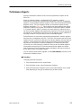
H Performance Reports 5-5. . . . . . . . . . . . . . . . . . . . . . . . . . . . . . . . . . . . . . . . . . . .
H Ethernet Statistics 5-8. . . . . . . . . . . . . . . . . . . . . . . . . . . . . . . . . . . . . . . . . . . . . . .
H IP Routing Table 5-10. . . . . . . . . . . . . . . . . . . . . . . . . . . . . . . . . . . . . . . . . . . . . . . .
H Alarms 5-12. . . . . . . . . . . . . . . . . . . . . . . . . . . . . . . . . . . . . . . . . . . . . . . . . . . . . . . . .
H SNMP Traps 5-13. . . . . . . . . . . . . . . . . . . . . . . . . . . . . . . . . . . . . . . . . . . . . . . . . . .
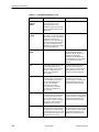
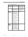
H Troubleshooting 5-15. . . . . . . . . . . . . . . . . . . . . . . . . . . . . . . . . . . . . . . . . . . . . . . . .
H Test Jacks 5-17. . . . . . . . . . . . . . . . . . . . . . . . . . . . . . . . . . . . . . . . . . . . . . . . . . . . .
H Test Commands 5-18. . . . . . . . . . . . . . . . . . . . . . . . . . . . . . . . . . . . . . . . . . . . . . . .
H Remote Loopback Tests 5-19. . . . . . . . . . . . . . . . . . . . . . . . . . . . . . . . . . . . . . . . .
Sending a Line Loopback Up or Down 5-19. . . . . . . . . . . . . . . . . . . . . . . . .
Sending a V.54 or ANSI FT1 Activation/Deactivation Sequence 5-20. . . .
H Local Loopback Tests 5-20. . . . . . . . . . . . . . . . . . . . . . . . . . . . . . . . . . . . . . . . . . . .
Starting a Line Loopback 5-21. . . . . . . . . . . . . . . . . . . . . . . . . . . . . . . . . . . . .
Starting a Payload Loopback 5-22. . . . . . . . . . . . . . . . . . . . . . . . . . . . . . . . . .
Starting a DTE Loopback 5-22. . . . . . . . . . . . . . . . . . . . . . . . . . . . . . . . . . . . .
Starting a Repeater Loopback 5-23. . . . . . . . . . . . . . . . . . . . . . . . . . . . . . . . .
Starting a Data Channel Loopback 5-24. . . . . . . . . . . . . . . . . . . . . . . . . . . . .
Starting a Data Terminal Loopback 5-25. . . . . . . . . . . . . . . . . . . . . . . . . . . .
Aborting Loopbacks 5-25. . . . . . . . . . . . . . . . . . . . . . . . . . . . . . . . . . . . . . . . . .
H Test Patterns 5-26. . . . . . . . . . . . . . . . . . . . . . . . . . . . . . . . . . . . . . . . . . . . . . . . . . .
Sending Network QRSS or Network 1-in-8 Test Patterns 5-26. . . . . . . . . .
Sending Port QRSS or Port 511 Test Patterns 5-27. . . . . . . . . . . . . . . . . . .
Monitoring Network QRSS Test Patterns 5-27. . . . . . . . . . . . . . . . . . . . . . .
Monitoring Port QRSS or Port 511 Test Patterns 5-27. . . . . . . . . . . . . . . . .
Aborting Test Patterns 5-28. . . . . . . . . . . . . . . . . . . . . . . . . . . . . . . . . . . . . . . .
H Lamp Test 5-28. . . . . . . . . . . . . . . . . . . . . . . . . . . . . . . . . . . . . . . . . . . . . . . . . . . . . .
Starting a Lamp Test 5-28. . . . . . . . . . . . . . . . . . . . . . . . . . . . . . . . . . . . . . . . .
Aborting a Lamp Test 5-28. . . . . . . . . . . . . . . . . . . . . . . . . . . . . . . . . . . . . . . .
H Displaying DSU/CSU Test Status 5-29. . . . . . . . . . . . . . . . . . . . . . . . . . . . . . . . . .
A Asynchronous Terminal Menu
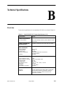
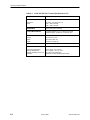
B Technical Specifications
H Overview B-1. . . . . . . . . . . . . . . . . . . . . . . . . . . . . . . . . . . . . . . . . . . . . . . . . . . . . .

Contents
iv
3162-A2-GB20-40
August 2000
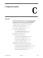
C Configuration Options
H Overview C-1. . . . . . . . . . . . . . . . . . . . . . . . . . . . . . . . . . . . . . . . . . . . . . . . . . . . . .
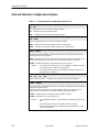
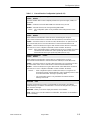
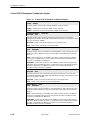
H Network Interface Configuration Options C-2. . . . . . . . . . . . . . . . . . . . . . . . . . .
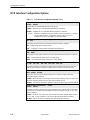
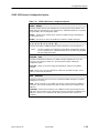
H DTE Interface Configuration Options C-4. . . . . . . . . . . . . . . . . . . . . . . . . . . . . . .
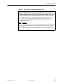
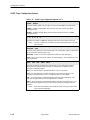
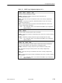
H Sync Data Port Configuration Options C-6. . . . . . . . . . . . . . . . . . . . . . . . . . . . .
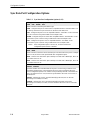
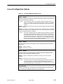
H Cross Connect Configuration Options C-11. . . . . . . . . . . . . . . . . . . . . . . . . . . . . .
DTE-to-Network Assignment Options C-11. . . . . . . . . . . . . . . . . . . . . . . . . .
Sync Data Port Assignment Options C-12. . . . . . . . . . . . . . . . . . . . . . . . . . .
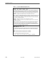
H General Configuration Options C-15. . . . . . . . . . . . . . . . . . . . . . . . . . . . . . . . . . . .
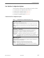
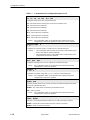
H User Interface Configuration Options C-17. . . . . . . . . . . . . . . . . . . . . . . . . . . . . .
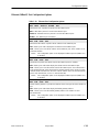
Communication Port Configuration Options C-17. . . . . . . . . . . . . . . . . . . . .
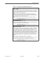
External Device Configuration Options C-19. . . . . . . . . . . . . . . . . . . . . . . . .
Telnet Sessions Configuration Options C-22. . . . . . . . . . . . . . . . . . . . . . . . .
Ethernet (10BaseT) Port Configuration Options C-23. . . . . . . . . . . . . . . . . .
H Alarm and Trap Configuration Options C-24. . . . . . . . . . . . . . . . . . . . . . . . . . . . .
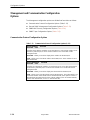
H Management and Communication Configuration Options C-26. . . . . . . . . . . . .
Communication Protocol Configuration Options C-26. . . . . . . . . . . . . . . . .
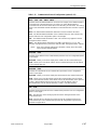
General SNMP Management Configuration Options C-28. . . . . . . . . . . . . .
SNMP NMS Security Configuration Options C-29. . . . . . . . . . . . . . . . . . . . .
SNMP Traps Configuration Options C-30. . . . . . . . . . . . . . . . . . . . . . . . . . . .
H Configuration Worksheets C-33. . . . . . . . . . . . . . . . . . . . . . . . . . . . . . . . . . . . . . . .
D Pin Assignments
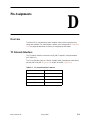
H Overview D-1. . . . . . . . . . . . . . . . . . . . . . . . . . . . . . . . . . . . . . . . . . . . . . . . . . . . . .
H T1 Network Interface D-1. . . . . . . . . . . . . . . . . . . . . . . . . . . . . . . . . . . . . . . . . . . .
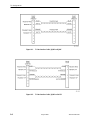
H DTE Drop/Insert Interface D-3. . . . . . . . . . . . . . . . . . . . . . . . . . . . . . . . . . . . . . . .
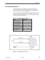
H 10BaseT Connector D-4. . . . . . . . . . . . . . . . . . . . . . . . . . . . . . . . . . . . . . . . . . . . .
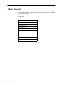
H COM Port Interface D-5. . . . . . . . . . . . . . . . . . . . . . . . . . . . . . . . . . . . . . . . . . . . . .
H Serial Crossover Cable D-7. . . . . . . . . . . . . . . . . . . . . . . . . . . . . . . . . . . . . . . . . .
H EIA-530-A Port Interface Connector D-8. . . . . . . . . . . . . . . . . . . . . . . . . . . . . . .
H EIA-530-A-to-RS-449 Adapter D-9. . . . . . . . . . . . . . . . . . . . . . . . . . . . . . . . . . . .
H EIA-530-A-to-V.35 Adapter D-11. . . . . . . . . . . . . . . . . . . . . . . . . . . . . . . . . . . . . . .
H EIA-530-A-to-X.21 Adapter D-13. . . . . . . . . . . . . . . . . . . . . . . . . . . . . . . . . . . . . . .
H External Clock Interface D-14. . . . . . . . . . . . . . . . . . . . . . . . . . . . . . . . . . . . . . . . . .

Contents
v
3162-A2-GB20-40
August 2000
E SNMP MIB Objects
H Overview E-1. . . . . . . . . . . . . . . . . . . . . . . . . . . . . . . . . . . . . . . . . . . . . . . . . . . . . .
H MIB II (RFC 1213) E-1. . . . . . . . . . . . . . . . . . . . . . . . . . . . . . . . . . . . . . . . . . . . . . .
System Group, MIB II E-2. . . . . . . . . . . . . . . . . . . . . . . . . . . . . . . . . . . . . . . .
Interface Group, MIB II E-3. . . . . . . . . . . . . . . . . . . . . . . . . . . . . . . . . . . . . . .
IP Group, MIB II E-7. . . . . . . . . . . . . . . . . . . . . . . . . . . . . . . . . . . . . . . . . . . . .
ICMP Group, MIB II E-10. . . . . . . . . . . . . . . . . . . . . . . . . . . . . . . . . . . . . . . . . .
TCP Group, MIB II E-10. . . . . . . . . . . . . . . . . . . . . . . . . . . . . . . . . . . . . . . . . . .
UDP Group, MIB II E-10. . . . . . . . . . . . . . . . . . . . . . . . . . . . . . . . . . . . . . . . . . .
Transmission Group, MIB II E-11. . . . . . . . . . . . . . . . . . . . . . . . . . . . . . . . . . .
SNMP Group, MIB II E-11. . . . . . . . . . . . . . . . . . . . . . . . . . . . . . . . . . . . . . . . .
H DS1/E1 MIB (RFC 1406) E-11. . . . . . . . . . . . . . . . . . . . . . . . . . . . . . . . . . . . . . . . .
Near End Group, DS1/E1 MIB E-12. . . . . . . . . . . . . . . . . . . . . . . . . . . . . . . . .
Far End Group, DS1/E1 MIB E-16. . . . . . . . . . . . . . . . . . . . . . . . . . . . . . . . . .
DS1 Fractional Group, DS1/E1 MIB E-16. . . . . . . . . . . . . . . . . . . . . . . . . . . .
H RS-232-like MIB (RFC 1317) E-17. . . . . . . . . . . . . . . . . . . . . . . . . . . . . . . . . . . . .
General Port Table, RS-232-like MIB E-17. . . . . . . . . . . . . . . . . . . . . . . . . . .
Asynchronous Port Table, RS-232-like MIB E-19. . . . . . . . . . . . . . . . . . . . .
Synchronous Port Table, RS-232-like MIB E-20. . . . . . . . . . . . . . . . . . . . . .
Input Signal Table, RS-232-like MIB E-20. . . . . . . . . . . . . . . . . . . . . . . . . . . .
Output Signal Table, RS-232-like MIB E-21. . . . . . . . . . . . . . . . . . . . . . . . . .
H Generic-Interface MIB Extensions (RFC 1229) E-21. . . . . . . . . . . . . . . . . . . . . .
Generic Interface Test Table, Generic Interface MIB E-22. . . . . . . . . . . . . .
H Enterprise MIB E-24. . . . . . . . . . . . . . . . . . . . . . . . . . . . . . . . . . . . . . . . . . . . . . . . . .
F IP Network Addressing Scenario
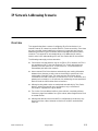
H Overview F-1. . . . . . . . . . . . . . . . . . . . . . . . . . . . . . . . . . . . . . . . . . . . . . . . . . . . . .
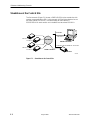
H Standalone at the Central Site F-2. . . . . . . . . . . . . . . . . . . . . . . . . . . . . . . . . . . .
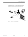
H Local Carrier with Remote Standalone F-3. . . . . . . . . . . . . . . . . . . . . . . . . . . . .
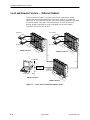
H Local and Remote Carriers — Different Subnets F-4. . . . . . . . . . . . . . . . . . . .
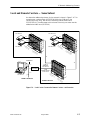
H Local and Remote Carriers — Same Subnet F-5. . . . . . . . . . . . . . . . . . . . . . . .
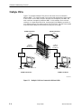
H Multiple NMSs F-6. . . . . . . . . . . . . . . . . . . . . . . . . . . . . . . . . . . . . . . . . . . . . . . . . .
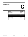
G Equipment List
Glossary
Index

Contents
vi
3162-A2-GB20-40
August 2000
This page intentionally left blank.

vii
3162-A2-GB20-40
August 2000
About This Guide
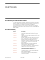
Document Purpose and Intended Audience
This user’s guide contains installation, operation, and maintenance information
for the ACCULINK 3162 Data Service Unit (DSU)/Channel Service Unit (CSU).
It is assumed that you are familiar with the operation of digital data
communication equipment. You should also be familiar with Simple Network
Management Protocol (SNMP) if you want your DSU/CSU to be managed by an
SNMP manager.
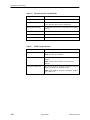
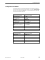
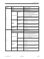
Document Summary
Section Description
Chapter 1 Introduction. Describes the 3162 DSU/CSU and its
features.
Chapter 2 Installation. Describes how to install the DSU/CSU and
make connections.
Chapter 3 Operation. Provides information about the front panel
LEDs, and instructions for using an asynchronous
terminal to control and configure the DSU/CSU.
Chapter 4 Configuration. Contains procedures for configuring the
Ethernet port, the COM port, DS0 channels, and
access security.
Chapter 5 Monitoring and Testing. Contains procedures for
monitoring, testing, and troubleshooting.
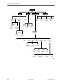
Appendix A Asynchronous Terminal Menu. Contains a menu tree
showing all the main front panel functions.
Appendix B Technical Specifications. Contains technical
specifications for the 3162 DSU/CSU.
Appendix C Configuration Options. Contains all the configuration
options and default settings.
Appendix D Pin Assignments. Shows the pin assignments for
connectors and cables.

About This Guide
viii
3162-A2-GB20-40
August 2000
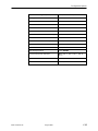
Section Description
Appendix E SNMP MIB Objects. Describes the MIB objects
supported by the DSU/CSU.
Appendix F IP Network Addressing Scenario. Provides sample IP
addressing scheme.
Appendix G Equipment List. Contains order numbers for cables and
other related parts.
Glossary Defines abbreviations and terms used in this
document.
Index Lists key terms, concepts, and sections in alphabetical
order.
Product-Related Documents
Document Number Document Title
3160-A2-GB24 ACCULINK DSU/CSU, Models 3160-A4, 3161,
3164-A2, and 3165-A4, Operator’s Guide
3162-A2-GL11 ACCULINK 3162 DSU/CSU Quick Reference
Contact your sales or service representative to order additional product
documentation.
Paradyne documents are also available on the World Wide Web at:
www.paradyne.com

About This Guide
ix
3162-A2-GB20-40
August 2000
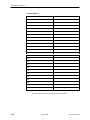
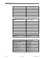
Reference Documents
AT&T Technical Reference 54016
AT&T Technical Reference 62411
ANSI T1.403-1989
Industry Canada CS-03
CSA-22.2 No. 950
Industry Canada (ICES)-003
FCC Part 15
FCC Part 68
UL 1950
Management Information Base for Network Management of TCP/IP- Based
Internets: MIBII. RFC 1213, March 1991
Definitions of Managed Objects for the DS1 and E1 Interface Types. RFC 1406,
January 1993
Definitions of Managed Objects for RS-232-like Hardware Devices. RFC 1317,
April 1992
Extensions to the Generic-Interface MIB. RFC 1229, May 1991

About This Guide
x
3162-A2-GB20-40
August 2000
This page intentionally left blank.

1-1
3162-A2-GB20-40
August 2000
Introduction
1
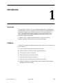
Overview
The ACCULINKr DSU/CSU acts as an interface between the T1 digital network
and the customer premises equipment, converting signals received from the DTE
(Data Terminal Equipment) to bipolar signals that can be transmitted over T1
lines. Typical applications include shared access to network-based services,
Local Area Network (LAN)/Wide Area Network (WAN) interconnection, and
fractional T1 network applications.
In addition to the T1 network interface and the DTE Drop/Insert (DSX-1)
interface, the Model 3162 provides two synchronous data ports.
Features
The DSU/CSU optimizes network performance with a wide range of features such
as the following:
H Local or remote configuration and operation flexibility.
H Several loopback capabilities and test pattern generators.
H DTE Drop/Insert (DSX-1) capability.
H Asynchronous terminal interface support.
H Alarm message display/print capability.
H Telnet access for remote asynchronous terminal operations.
H Network management provided through industry-standard Simple Network
Management Protocol (SNMP).

Introduction
1-2
3162-A2-GB20-40
August 2000
DTE Drop/Insert (DSX-1) Interface
The DTE Drop/Insert interface allows DTEs/PBXs that support the DS1 signal
format to share the T1 network with other high-speed equipment.
Asynchronous Terminal Interface Support
The DSU/CSU can be configured and managed from an asynchronous (async)
terminal. The asynchronous terminal’s full screen display uses a menu hierarchy
to perform device-control operations.
Chapter 3, Operation, provides operational examples to help you become familiar
with the use of the asynchronous terminal for DSU/CSU control.
Alarm Message Capability
The DSU/CSU can be attached, either locally or remotely, to an ASCII terminal or
printer to display or print alarm messages. Alarms can also be displayed on a PC
that is using a terminal emulation package.
Chapter 5, Monitoring and Testing, provides a list of alarm messages.
Telnet Access
Remote async terminal operations can be performed using Telnet access. Telnet
is a Transmission Control Protocol/Internet Protocol (TCP/IP) service that
supports a virtual terminal interface.
SNMP Management Support
SNMP is a network management protocol that is used to monitor network
performance and status, and to report alarms (i.e., traps). To function, SNMP
requires a manager consisting of a software program housed within a workstation
or PC; an agent consisting of a software program housed within a device (e.g.,
the DSU/CSU); and a Management Information Base (MIB) consisting of a
database of managed objects. The DSU/CSU can be managed by any
industry-standard SNMP manager.
Two link layer protocols, Point-to-Point Protocol (PPP) and Serial Line Internet
Protocol (SLIP), are supported for connection to an external SNMP manager or
network device (e.g., a router).
The SNMP manager or network device can be directly connected to the
communications (COM) port or can be accessed via Ethernet using the 10BaseT
port.
The SNMP management system can communicate to the DSU/CSU remotely
through the Facility Data Link (FDL) or the synchronous data port’s Embedded
Data Link (EDL).

Introduction
1-3
3162-A2-GB20-40
August 2000
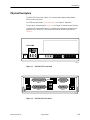
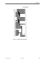
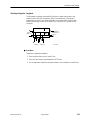
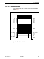
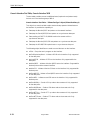
Physical Description
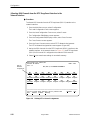
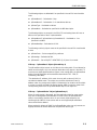
The DSU/CSU front panel (Figure 1-1) contains twelve light-emitting diodes
(LEDs) and six test jacks.
The LEDs are described in Front Panel LEDs in Chapter 3, Operation.
The test jacks are described in Test Jacks in Chapter 5, Monitoring and Testing.
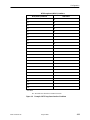
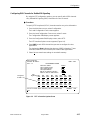
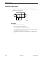
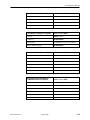
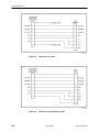
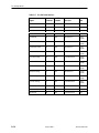
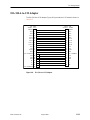
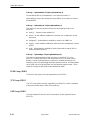
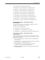
The DSU/CSU rear panel (Figure 1-2) contains the connectors required for the
operation of the DSU/CSU. The connectors and their functions are listed in
Table 1-1.
F1 F2 F3
OK
FAIL TEST SIG OOF ALRM
NETWORK RXD
EER SIG ALRM PDVOOF BPV
3162
ACCULINK
In
Out
In
Out
In
Out
NET
MON EQPT
DTR TXD CTS RTS
496-15001
Figure 1-1. 3162 DSU/CSU Front Panel
00-16852
POWER
PORT 2
PORT 1
10 BASE-T
COM DSX-1MODEM
EXT CLK
NETWORK
Figure 1-2. 3162 DSU/CSU Rear Panel

Introduction
1-4
3162-A2-GB20-40
August 2000
Table 1-1. DSU/CSU Rear Panel Connectors
Name
Function
POWER Supplies power to the DSU/CSU by providing an attachment for the
AC power module.
10 BASE-T PORT
Supports connection to an Ethernet LAN.
COM PORT Provides access to a locally connected PC, ASCII terminal or
printer, SNMP management link, or asynchronous terminal
interface.
NETWORK Provides access to the T1 network.
DTE Provides access to the DTE Drop/Insert (DSX-1) interface.
CLOCK IN Used to attach an external clock to the DSU/CSU.
PORTs 1–2 Used to connect the customer’s synchronous data DTE to the
DSU/CSU.
Page is loading ...
Page is loading ...
Page is loading ...
Page is loading ...
Page is loading ...
Page is loading ...
Page is loading ...
Page is loading ...
Page is loading ...
Page is loading ...
Page is loading ...
Page is loading ...
Page is loading ...
Page is loading ...
Page is loading ...
Page is loading ...
Page is loading ...
Page is loading ...
Page is loading ...
Page is loading ...
Page is loading ...
Page is loading ...
Page is loading ...
Page is loading ...
Page is loading ...
Page is loading ...
Page is loading ...
Page is loading ...
Page is loading ...
Page is loading ...
Page is loading ...
Page is loading ...
Page is loading ...
Page is loading ...
Page is loading ...
Page is loading ...
Page is loading ...
Page is loading ...
Page is loading ...
Page is loading ...
Page is loading ...
Page is loading ...
Page is loading ...
Page is loading ...
Page is loading ...
Page is loading ...
Page is loading ...
Page is loading ...
Page is loading ...
Page is loading ...
Page is loading ...
Page is loading ...
Page is loading ...
Page is loading ...
Page is loading ...
Page is loading ...
Page is loading ...
Page is loading ...
Page is loading ...
Page is loading ...
Page is loading ...
Page is loading ...
Page is loading ...
Page is loading ...
Page is loading ...
Page is loading ...
Page is loading ...
Page is loading ...
Page is loading ...
Page is loading ...
Page is loading ...
Page is loading ...
Page is loading ...
Page is loading ...
Page is loading ...
Page is loading ...
Page is loading ...
Page is loading ...
Page is loading ...
Page is loading ...
Page is loading ...
Page is loading ...
Page is loading ...
Page is loading ...
Page is loading ...
Page is loading ...
Page is loading ...
Page is loading ...
Page is loading ...
Page is loading ...
Page is loading ...
Page is loading ...
Page is loading ...
Page is loading ...
Page is loading ...
Page is loading ...
Page is loading ...
Page is loading ...
Page is loading ...
Page is loading ...
Page is loading ...
Page is loading ...
Page is loading ...
Page is loading ...
Page is loading ...
Page is loading ...
Page is loading ...
Page is loading ...
Page is loading ...
Page is loading ...
Page is loading ...
Page is loading ...
Page is loading ...
Page is loading ...
Page is loading ...
Page is loading ...
Page is loading ...
Page is loading ...
Page is loading ...
Page is loading ...
Page is loading ...
Page is loading ...
Page is loading ...
Page is loading ...
Page is loading ...
Page is loading ...
Page is loading ...
Page is loading ...
Page is loading ...
Page is loading ...
Page is loading ...
Page is loading ...
Page is loading ...
Page is loading ...
Page is loading ...
Page is loading ...
Page is loading ...
Page is loading ...
Page is loading ...
Page is loading ...
Page is loading ...
Page is loading ...
Page is loading ...
Page is loading ...
Page is loading ...
Page is loading ...
Page is loading ...
Page is loading ...
Page is loading ...
Page is loading ...
Page is loading ...
Page is loading ...
Page is loading ...
Page is loading ...
Page is loading ...
Page is loading ...
Page is loading ...
Page is loading ...
Page is loading ...
Page is loading ...
Page is loading ...
Page is loading ...
Page is loading ...
Page is loading ...
Page is loading ...
Page is loading ...
Page is loading ...
Page is loading ...
Page is loading ...
Page is loading ...
Page is loading ...
Page is loading ...
Page is loading ...
Page is loading ...
Page is loading ...
Page is loading ...
Page is loading ...
Page is loading ...
Page is loading ...
-
 1
1
-
 2
2
-
 3
3
-
 4
4
-
 5
5
-
 6
6
-
 7
7
-
 8
8
-
 9
9
-
 10
10
-
 11
11
-
 12
12
-
 13
13
-
 14
14
-
 15
15
-
 16
16
-
 17
17
-
 18
18
-
 19
19
-
 20
20
-
 21
21
-
 22
22
-
 23
23
-
 24
24
-
 25
25
-
 26
26
-
 27
27
-
 28
28
-
 29
29
-
 30
30
-
 31
31
-
 32
32
-
 33
33
-
 34
34
-
 35
35
-
 36
36
-
 37
37
-
 38
38
-
 39
39
-
 40
40
-
 41
41
-
 42
42
-
 43
43
-
 44
44
-
 45
45
-
 46
46
-
 47
47
-
 48
48
-
 49
49
-
 50
50
-
 51
51
-
 52
52
-
 53
53
-
 54
54
-
 55
55
-
 56
56
-
 57
57
-
 58
58
-
 59
59
-
 60
60
-
 61
61
-
 62
62
-
 63
63
-
 64
64
-
 65
65
-
 66
66
-
 67
67
-
 68
68
-
 69
69
-
 70
70
-
 71
71
-
 72
72
-
 73
73
-
 74
74
-
 75
75
-
 76
76
-
 77
77
-
 78
78
-
 79
79
-
 80
80
-
 81
81
-
 82
82
-
 83
83
-
 84
84
-
 85
85
-
 86
86
-
 87
87
-
 88
88
-
 89
89
-
 90
90
-
 91
91
-
 92
92
-
 93
93
-
 94
94
-
 95
95
-
 96
96
-
 97
97
-
 98
98
-
 99
99
-
 100
100
-
 101
101
-
 102
102
-
 103
103
-
 104
104
-
 105
105
-
 106
106
-
 107
107
-
 108
108
-
 109
109
-
 110
110
-
 111
111
-
 112
112
-
 113
113
-
 114
114
-
 115
115
-
 116
116
-
 117
117
-
 118
118
-
 119
119
-
 120
120
-
 121
121
-
 122
122
-
 123
123
-
 124
124
-
 125
125
-
 126
126
-
 127
127
-
 128
128
-
 129
129
-
 130
130
-
 131
131
-
 132
132
-
 133
133
-
 134
134
-
 135
135
-
 136
136
-
 137
137
-
 138
138
-
 139
139
-
 140
140
-
 141
141
-
 142
142
-
 143
143
-
 144
144
-
 145
145
-
 146
146
-
 147
147
-
 148
148
-
 149
149
-
 150
150
-
 151
151
-
 152
152
-
 153
153
-
 154
154
-
 155
155
-
 156
156
-
 157
157
-
 158
158
-
 159
159
-
 160
160
-
 161
161
-
 162
162
-
 163
163
-
 164
164
-
 165
165
-
 166
166
-
 167
167
-
 168
168
-
 169
169
-
 170
170
-
 171
171
-
 172
172
-
 173
173
-
 174
174
-
 175
175
-
 176
176
-
 177
177
-
 178
178
-
 179
179
-
 180
180
-
 181
181
-
 182
182
-
 183
183
-
 184
184
-
 185
185
-
 186
186
-
 187
187
-
 188
188
-
 189
189
-
 190
190
-
 191
191
-
 192
192
-
 193
193
-
 194
194
-
 195
195
-
 196
196
-
 197
197
-
 198
198
-
 199
199


